EP1765524B1 - Siebeinrichtung und verfahren mit flexibler matte - Google Patents
Siebeinrichtung und verfahren mit flexibler matte Download PDFInfo
- Publication number
- EP1765524B1 EP1765524B1 EP05761840.7A EP05761840A EP1765524B1 EP 1765524 B1 EP1765524 B1 EP 1765524B1 EP 05761840 A EP05761840 A EP 05761840A EP 1765524 B1 EP1765524 B1 EP 1765524B1
- Authority
- EP
- European Patent Office
- Prior art keywords
- mat
- sieve mat
- sieve
- section
- sections
- Prior art date
- Legal status (The legal status is an assumption and is not a legal conclusion. Google has not performed a legal analysis and makes no representation as to the accuracy of the status listed.)
- Expired - Lifetime
Links
Images






Classifications
-
- B—PERFORMING OPERATIONS; TRANSPORTING
- B07—SEPARATING SOLIDS FROM SOLIDS; SORTING
- B07B—SEPARATING SOLIDS FROM SOLIDS BY SIEVING, SCREENING, SIFTING OR BY USING GAS CURRENTS; SEPARATING BY OTHER DRY METHODS APPLICABLE TO BULK MATERIAL, e.g. LOOSE ARTICLES FIT TO BE HANDLED LIKE BULK MATERIAL
- B07B1/00—Sieving, screening, sifting, or sorting solid materials using networks, gratings, grids, or the like
- B07B1/46—Constructional details of screens in general; Cleaning or heating of screens
- B07B1/48—Stretching devices for screens
- B07B1/485—Devices for alternately stretching and sagging screening surfaces
-
- B—PERFORMING OPERATIONS; TRANSPORTING
- B07—SEPARATING SOLIDS FROM SOLIDS; SORTING
- B07B—SEPARATING SOLIDS FROM SOLIDS BY SIEVING, SCREENING, SIFTING OR BY USING GAS CURRENTS; SEPARATING BY OTHER DRY METHODS APPLICABLE TO BULK MATERIAL, e.g. LOOSE ARTICLES FIT TO BE HANDLED LIKE BULK MATERIAL
- B07B1/00—Sieving, screening, sifting, or sorting solid materials using networks, gratings, grids, or the like
- B07B1/28—Moving screens not otherwise provided for, e.g. swinging, reciprocating, rocking, tilting or wobbling screens
-
- B—PERFORMING OPERATIONS; TRANSPORTING
- B07—SEPARATING SOLIDS FROM SOLIDS; SORTING
- B07B—SEPARATING SOLIDS FROM SOLIDS BY SIEVING, SCREENING, SIFTING OR BY USING GAS CURRENTS; SEPARATING BY OTHER DRY METHODS APPLICABLE TO BULK MATERIAL, e.g. LOOSE ARTICLES FIT TO BE HANDLED LIKE BULK MATERIAL
- B07B1/00—Sieving, screening, sifting, or sorting solid materials using networks, gratings, grids, or the like
- B07B1/46—Constructional details of screens in general; Cleaning or heating of screens
-
- B—PERFORMING OPERATIONS; TRANSPORTING
- B07—SEPARATING SOLIDS FROM SOLIDS; SORTING
- B07B—SEPARATING SOLIDS FROM SOLIDS BY SIEVING, SCREENING, SIFTING OR BY USING GAS CURRENTS; SEPARATING BY OTHER DRY METHODS APPLICABLE TO BULK MATERIAL, e.g. LOOSE ARTICLES FIT TO BE HANDLED LIKE BULK MATERIAL
- B07B1/00—Sieving, screening, sifting, or sorting solid materials using networks, gratings, grids, or the like
- B07B1/46—Constructional details of screens in general; Cleaning or heating of screens
- B07B1/4609—Constructional details of screens in general; Cleaning or heating of screens constructional details of screening surfaces or meshes
-
- B—PERFORMING OPERATIONS; TRANSPORTING
- B07—SEPARATING SOLIDS FROM SOLIDS; SORTING
- B07B—SEPARATING SOLIDS FROM SOLIDS BY SIEVING, SCREENING, SIFTING OR BY USING GAS CURRENTS; SEPARATING BY OTHER DRY METHODS APPLICABLE TO BULK MATERIAL, e.g. LOOSE ARTICLES FIT TO BE HANDLED LIKE BULK MATERIAL
- B07B1/00—Sieving, screening, sifting, or sorting solid materials using networks, gratings, grids, or the like
- B07B1/46—Constructional details of screens in general; Cleaning or heating of screens
- B07B1/4609—Constructional details of screens in general; Cleaning or heating of screens constructional details of screening surfaces or meshes
- B07B1/4645—Screening surfaces built up of modular elements
-
- B—PERFORMING OPERATIONS; TRANSPORTING
- B07—SEPARATING SOLIDS FROM SOLIDS; SORTING
- B07B—SEPARATING SOLIDS FROM SOLIDS BY SIEVING, SCREENING, SIFTING OR BY USING GAS CURRENTS; SEPARATING BY OTHER DRY METHODS APPLICABLE TO BULK MATERIAL, e.g. LOOSE ARTICLES FIT TO BE HANDLED LIKE BULK MATERIAL
- B07B1/00—Sieving, screening, sifting, or sorting solid materials using networks, gratings, grids, or the like
- B07B1/46—Constructional details of screens in general; Cleaning or heating of screens
- B07B1/4609—Constructional details of screens in general; Cleaning or heating of screens constructional details of screening surfaces or meshes
- B07B1/4654—Corrugated Screening surfaces
Definitions
- the field of the present invention relates to vibratory screening machines using flexible mats according to the precharacterizing part of claim 1.
- prior art screening machines have consisted of an elongated support frame with a mobile, deformable sieve mat, typically comprised of a plurality of sieve mat sections and having lateral edges extending in the direction of the length of the support frame in a series of alternating immobile and mobile sieve mat carriers mounted on the support frame and extending transversely along the length thereof, the sieve mat sections being affixed to the carriers with the mobile carriers being movable with respect to the support frame in the direction of the length of the support frame.
- the individual screen mat sections are alternately tensioned and relaxed.
- the screening machine has a flat sieve mat with seals between the sieve mat and the adjacent side walls.
- U.S. Patent No. 5,062,949 discloses a screening machine in accordance with the preamble of claim 1, having lateral sieve mat sides that are extended upwardly relative to the carriers and raised to form vertical side walls for the sieve mat, the carriers further including support shoulders for the lateral sides of the sieve mat, and the lateral sides being free of perforations in the vicinity of the shoulder.
- U.S. Patent No. 5,062,949 also discloses a method of material screening.
- US-A-3971715 demonstrates a device for sieving, sorting, filtering and the like involving a flexible material mat
- EP-A-0277936 demonstrates a side sealing device for a device for sieving
- US-B-6669027 demonstrates a vibratory screening device involving another flexible mat that is of a corrugated shape.
- a screening apparatus includes a frame assembly comprised of a main support frame section and a movable support frame section movably mounted on or connected to the main support frame section wherein the sieve mat comprises upwardly curved lateral sides forming a non-vertical, gradually curved shape which contains and redirects material toward the center of the sieve mat and away from the lateral rims.
- the movable support section is supported on the main frame section via a plurality of shear springs each arranged with its compression axis disposed horizontally between the main support frame section and movable support frame section.
- the movable support section is further connected to the main frame section via vertical stabilizers or leaf springs, the vertical stabilizers permitting longitudinal movement between the movable support section and the main frame section, but inhibiting vertical and/or lateral movement therebetween.
- an improved mat clamping system is described.
- Figs. 1-5 illustrate a screening machine 10 according to a preferred embodiment.
- the screening machine 10 includes a first support frame 40 which is supported on a foundation 5 or machine frame (not shown) via a plurality of mounts, each mount being supported on a corresponding isolation spring.
- the screening machine of Fig. 1 is illustrated with four mounts, but other suitable number of mounts may be implemented.
- the side elevation view of Fig. 1 shows mount 22 on isolation spring 32 and mount 24 on isolation spring 34. Though not visible in Fig. 1 , the other pair of corresponding mounts and isolation springs are symmetrically disposed on the opposite side of the support frame 40.
- Fig. 2 illustrates mount 22 supported on isolation spring 32 on one side of the support frame 40 and mount 26 supported on isolation spring 36 on the other side.
- the support frame sides 40a and 41 a are interconnected by a connecting member or base element 20 extending between the support frame sides 40a and 41 a and the between the mounts 22 and 26.
- the connecting member 20 provides for stiffening connection between the support frame sides 40a and 41 a.
- the declination angle of the sieve mat 200 may change over the length of the unit, the actual mounting of the sieve mat 200 providing the desired declination angle(s).
- the declination angle of the sieve mat 200 may decrease either continuously or in stages/steps.
- the declination angle of the sieve mat 200 at the first sieve mat section 202 may be at 20° and decrease to 15° or 10° at the last mat section 240.
- a continuous "banana" type declination may provide operational, efficiency and/or wear advantages and potentially decrease the overall machine footprint.
- a drive shaft 110 is supported and mounted by bearings 112, 114 which are in turn mounted onto the main support frame 40.
- the shaft 110 is rotationally driven by the drive motor (the drive motor being schematically illustrated as element 117)
- an orbital vibrating motion is applied by the eccentrics 116 and 118 disposed on opposite ends of the shaft 110.
- the vibration could be applied by a single eccentric on a single side of the unit, but by extending the shaft 110 to opposite lateral sides of the unit and applying eccentrics on both sides of the support frame 40, a more balanced orbital vibratory force is applied across the support frame 40.
- a respective drive cover 119a, 119b is disposed over each of the drive ends for preventing access to the moving parts.
- the shaft 110 is illustrated as-a 15.2 cm (six-inch) diameter internal shaft passing through the bearings 112, 114 and extending out through the entire width of the support frame 40.
- the shaft 110 is surrounded by a fixed 20.3 cm (eight-inch) pipe 120 which extends between the mounting of the bearings 112, 114.
- the dimensions and locations of the shaft 110 and the pipe 120 are given merely as examples to illustrate relative sizes between the shaft and pipe components.
- the pipe 120 has end flanges which secure the pipe to the side frame assembly at the mounts for the bearings 112, 114.
- the pipe 120 provides for lateral support and stiffening between the bearing shaft mounts.
- the eccentrics 116, 118 on opposite sides of the shaft 110 are preferably located at the same angular position relative to the shaft 110 so as to provide a balanced application of the orbital vibration force from the shaft 110 through the bearings 112, 114 and into both sides of the support frame 40.
- the drive shaft 110 may be positioned near the machine center of gravity or at some other suitable location.
- the drive shaft 110 disclosed above is just one type of suitable drive mechanism.
- the drive mechanism may comprise a single drive shaft 110 or may comprise multiple shafts driven by one or more drive motors.
- the sieve mat 200 extends longitudinally across the length of the screening apparatus 10 from the inlet section 41 (shown at the right hand side of Fig. 1 ) to the outlet side on the left.
- the sieve mat 200 may comprise a single piece of material
- the sieve mat 200 is preferably a series of removable transverse sections or strips 202, 204, 206, 208, 210 ... 240 with each mat section being supported by a pair of transverse mat supports 302, 304, 306, 308, 310 ... 342.
- the sieve mat supports are in the form of square tubes arranged with a corner disposed tangentially to the mat 200.
- the illustrated square tube configuration and tangential orientation provides a desirably high strength and stiffness to weight ratio
- other shapes and orientations for the mat supports may be utilized.
- One such example are the rectangular tubes described below with respect to Fig. 9 et seq. whereby the long sides of the rectangle are vertically oriented.
- the sieve mat supports 302, 304, etc. are alternately connected to either the main support frame 40 or the movable support frame section (also referred to as the balancer 50).
- the frame tube supports (302, 306, 310 ... 342) are connected to the main support frame section and the balancer tube supports (304, 308, 312 ... 340) are connected to the balancer 50.
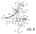
- the balancer 50 is supported via shear springs 60 and/or the vertical stabilizers 420 etc. as will be described below in further detail with respect to Figs. 3 and 5 .
- Each sieve mat section is connected on one end to a frame tube support (302, 306, 310 ... 342) and on the other end to a balancer tube support (304, 308, 312 ... 340).
- mat section 206 is connected on the upstream end to frame tube support 306 and on the downstream end to balancer tube 308. The operative functions of these connections will be described in further detail below.
- the apparatus 10 is symmetrically configured with each of the lateral sides (i.e. the left and right sides as viewed in Figs. 2 and 3 ) having like configuration.
- each of the lateral sides i.e. the left and right sides as viewed in Figs. 2 and 3
- the other side need not be entirely symmetrical.
- the slope of the upturned section 200a of the mat section 210 of Fig. 2 may be of a different curvature than the upturned section 200b.
- FIG. 2 illustrates detailed cross-section of Fig. 1 taken along line 2-2 whereby a frame tube assembly 310 is supported directly to the main support frame 40 via connector 42.
- the frame tube 310 comprises a square tubing arranged below the sieve mat 200 extending transversely along the width of the frame 40.
- the frame tube 310 includes an end flange 350 welded thereon for attachment to the connector 42.
- the connector 42 has four holes which have been drilled and tapped for accepting the bolts 352 which secure the flange 350 onto the connector 42.
- the connector 42 is in turn connected by a series of four bolts 46 which are secured into tapped holes located in the connector 42 as best shown in Figs. 4 and 6 .
- the frame tube 310 is directly connected to the support frame 40 both at a lower section 40a and then upper section 40b by a connection through the connector 42.
- Other connection mechanisms may be used such as through bolt and nut, welding, rivet, or any suitable fastener.
- Each of the balancer tube supports 304, 308, 312 ... 340 has essentially the same configuration and the description of one of the balancer tube assemblies should provide adequate description for any of the other balancer tube assemblies.
- the balance tube assembly is shown with reference to Figs. 3 , 5 and 6 where the balance tube 308 from Fig. 1 is illustrated in more detail. As best shown in Figs. 5 and 6 , the balance tube 308 and flange 360 are the same configuration as the frame tube 306 and flange 350.
- the balance tube 308 is mounted differently, however, as the flange 360 at the end of the tube 308 is connected to a spacer 52 which in turn is mounted to the balancer 50.
- the balancer 50 approximately extends the length of the unit 10 and is spring-mounted to the support frame 40 via a plurality of shear springs 60 and vertical stabilizers 420, 440 etc.
- Each shear spring 60 is oriented with its compression axis 62 disposed horizontally between the angular upper section 40c of the support frame 40 and the balancer 50.
- the shear spring 60 allows the balance tube 308 to move in any direction perpendicular to the plane of Fig. 5 placing the spring in shear whereas placing the spring in compression or tension along axis 62 would provide for relatively smaller movement along that lateral direction.
- the unit 10 will Include a plurality of shear springs also known as shear blocks installed on each side thereof providing for a balanced and even support for the balancer.
- the machine includes ten shear springs disposed on each side of the unit, but any suitable number of shear springs may be employed.
- the shear springs blocks may be comprised of any suitable resilient material of any durometer, such as rubber or polyurethane, and arranged to allow a difference in motion in the longitudinal directions while inhibiting motion in the transverse direction.
- the shear springs permit motion in the desired direction and provide a spring force (rate) for that desired motion.
- the sections 202, 204, 206, etc. of the frame mat are transversely connected to the respective frame tube or balancer tube along the length of the mat 200. Any suitable attachment scheme may be used.
- Fig. 6 illustrates frame tube 306 having an angle bar 402 which is welded to one side of the tube 306 and having an upper section 402a which contacts the undersurface of the mat sections 204, 206.
- a top clamp bar 404 sandwiches the mat sections 204, 206 along the width, and the mat sections 204, 206 are secured by a plurality of spaced bolts 406 along the transverse width of the frame tube support 306.
- the balance tube 308 includes an angle bar 412 secured on one side thereof and having an upper bar section 412a that supports the undersurface of the mat sections 206, 208 with the clamp bar 414 being secured by a plurality of spaced bolts 416 along the transverse width of the balance tube 308 sandwiching the mat sections 206, 208 therebetween.
- the construction of the like components for the frame tube assembly 310 is the same as frame tube assembly 306 and the construction of the like components for the balancer tube assembly 312 is the same as balancer tube assembly 308 and thus are not repeated.
- the mat sections are secured to the respective frame tube or balancer tube with the adjacent mat sections positioned end-to-end, the ends butting up to each other and secured between the top clamp bar and the angle bar upper section.
- the mat sections may have ends constructed so as to mate with a tongue-and-groove configuration, include alignment notches and teeth, or as shown in the embodiment of Fig. 7 below, may be designed with an overlap.
- the mat sections may be connected via bolts as shown, or alternately via fastening wedges or other suitable boltless connection.
- a boltless connection is described below with respect to Figs. 9-14 .
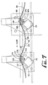
- Fig. 7 illustrates an alternate configuration for connecting the sieve mat sections to the respective frame tube and balance tube in which the respective mat sections overlap.
- Three sieve mat sections 208, 210, 212 are shown. From opposite directions, over the frame tube 310, both the trailing end 208b of the mat section 208 and the leading end 210a of the mat section 210 extend past the top clamp bar 404 and the angle bar upper section 402a of angle bar 402. The ends 208b and 210a are then secured together, pressed between top clamp bar section 404 and the angle bar upper section 402a as secured by bolt 406.
- the overlapping mat sections provide a large sealing surface area for preventing material from passing between the mat sections at this interconnection.
- the trailing edge of a mat section is positioned over the leading edge of the next (downstream) mat section providing for a more smooth contour for material moving in the flow direction.
- both the trailing end 210b of the mat section 210 and the leading end 212a of the mat section 212 extend past the top clamp bar 414 and the angle bar upper section 412a of angle bar 412.
- the ends 210b and 212a are then secured together, pressed between top clamp bar section 414 and the angle bar upper section 412a as secured by bolt 416.
- the overlapping mat sections provide a large sealing surface area for preventing material from passing between the mat sections at this interconnection.
- balancer 50 and correspondingly the balancer tubes 304, 308, 312 ... 340, are restrained in the vertical direction by operation of vertical stabilizers 420, 430, 440, 450 which connect between the balancer 50 and an upper section 40b of the support frame 40. Similar stabilizers are disposed on the other side of the unit 10.
- the construction of stabilizer 420 is representative of each of the other stabilizers 430, 440 etc. and is described in the following. As shown in Figs.
- the stabilizer 420 includes a pair of flexible spring plates 422, 424 secured at a lower end to the balancer 50 via bolts 423, 423 and secured at the upper end via bolts 425, 425, the spring plates 422, 424 being separated by spacer 426. Because of the plate geometry of the spring plates 422, 424 functioning as a leaf spring, the stabilizer 420 permits relative rocking or longitudinal movement in the direction of the arrow A in Fig. 6 as between the balancer tubes (as a group) and the frame tubes (as a group) but provides stiffening connection for inhibiting relative motion either vertically or laterally.
- the vertical stabilizers may be composed of any suitable device such as links, slats, plates, rocker arms, etc.
- the balancer assembly 50 is preferably suspended via the vertical stabilizers 420, 430, 440, etc. such that the weight of the balancer 50 is supported by the vertical stabilizers rather than the shear springs 60 thereby preventing pre-stressing or over-stressing the shear springs 60 in the vertical direction.
- the vertical stabilizers may be constructed of any suitable material such as metal (e.g. spring steel etc.) or a composite material.
- Both the vertical stabilizers 420, 430, 440 etc. and the horizontally mounted shear springs 60 serve to minimize lateral movement which reduces fatigue/wear on the sieve mat. Minimizing lateral movement is particularly useful in reducing fatigue/wear at the curvature area. By properly constraining the movement of the balancer, a consistent stroke may be achieved thereby enhancing component life and screening efficiency.
- the balancer tube supports 304, 308, 312 ... 340 mounted on the balancer 50 have the flexibility to move longitudinally (direction A in Fig. 6 ) relative to the frame tube supports 302, 306, 310 ... 342 via the shear springs 60 and the vertical stabilizers 420, 430, 440, etc..
- the distance between adjacent tubes alternately increases and decreases alternately flexing and unflexing the mat section therebetween.
- the sieve mat 200 may comprise a continuous unit for the various mat sections 202, 204, 206, etc. or may comprise separate transverse sections of a given length secured at each tube assembly via the bolt and clamps described above or some other suitable connection mechanism.
- Each of the sieve mat sections 202, 204, 206 etc. is preferably homogenous, uniform, unitary, and one-piece without splices.
- a configuration with separate sections permits replacement of a single section, such as section 204 or section 206, for replacement or repair without requiring replacement of remaining sieve mat sections such as sections 208, 210 etc..
- the sieve mat 200 includes perforations along its length (see for example the perforations 203 in mat section 210 of Fig. 6 ), the perforations being of a size and shape so as to permit particles of a given size to pass through for sorting.
- the individual perforations may be tapered and arranged in any suitable pattern and location.
- the inlet mat section 201 may comprise no perforations as that section may be designed to merely direct material into the screening area. It may be preferred that the perforations not extend at the connection sections under the clamp bars 404, 414 since that area is covered by the clamp bar anyway and thus can provide no screening function
- the perforation size, shape and pattern as well as the material and thickness will be chosen for the given material screening application.
- the sieve mat may be formed of any suitable material which has the desirable properties of flexibility and strength in addition to abrasion, rust and corrosion resistance.
- the material used for the sieve mats is mechanically strong and preferably a resilient elastomer with a balanced range of properties which is able to withstand deformation without loss of elasticity or dimensional accuracy.
- One such material is a resilient flexible polymer such as polyurethane for example.
- the sieve mats may be constructed of single homogenous material or may be reinforced such as with internal cables or bars, or with a suitable screen backing.
- the motion of the sieve mat sections is such that in the unflexed condition a sag will be formed, such as for example the sag in the mat sections 206, 208, 210 visible in Fig. 6 . Then moving to the flexed condition, the mat section will be snapped toward a flatter/straighter form.
- a sag will be formed, such as for example the sag in the mat sections 206, 208, 210 visible in Fig. 6 .
- the mat section will be snapped toward a flatter/straighter form.
- the flexible mat sections are individually tensioned and relaxed which breaks or loosens the adhesive bond between materials and between the material and the sieve mats. In the upstroke, material is impelled upwardly functioning much like a trampoline and air is drawn into and thru the material.
- the motion is such that in an example screening machine, the acceleration on the main support frame is about 3 g's, but the material on the sieve mat may experience up to 50g's.
- Sieve mat flexing may also stretch or bend the perforations helping to release particles that might become lodged in the perforations, a process called "breathing.”
- the flip flow method is useful for screening a wide variety of materials, including the more difficult applications such as:
- the lateral sides of the sieve mat 200 are formed with a gradually curved transition arc or turned-up section which will be generally referred to as element 200a in any of these figures.
- This curved section 200a serves to contain material being screened by the system, redirecting material riding up the sloped lateral edges back toward the central portion.
- the sieve mat 200 (comprised of the various mat sections) is secured and supported at the curved sections 200a by continuation of the clamp bar 404 and the upper section 402a of support bar 402 which extend approximately the entire lateral width of the respective mat sections, generally to the end of the mat 200.
- upper support bar section 402a Since an angled bar section 402 is impractical to form into the desired curvature, only a flat bar section (upper support bar section 402a) extends into the curved mat section 200a.
- the upper support bar section 402a is supported in its upwardly curved position via a gusset 311 welded between the frame tube 310 and the upper support bar section 402a.
- the balance tube 308 includes a gusset 325 attached to the balance tube 308 and the upper support bar section 412a forming the curved mat section 200a as disposed between the clamp bar 414 and the upper support bar section 412a.
- a sliding seal arrangement 45 is disposed along the top surface of the mat 200 near the top edge of the curved section 200a.
- the seal 45 is preferably a flexible material of sufficient resilience so as to maintain a fairly wide contact surface S 1 against the top of the mat surface over the range of relative motion between the two elements.
- the contact surface serves to provide the sealing surface for inhibiting passage of material.
- the seal 45 may be configured with a non-flexible element mounted so as to maintain a gap between the seal 45 and the top of the mat surface thereby forming a baffle for inhibiting passage of material.
- the gap configuration comprises a non-contact, low-friction system that may minimize friction wear.
- the curved section 200a of the preferred embodiment takes on a much more gradual curve resulting in a maximum rise to run ratio y/x of about 1.0.
- a preferred maximum rise/run ratio may be even more gradual, such as on the order of .75 or less.
- the arc of the curved section as shown in Fig. 8 is a gradual arc that will depend upon several factors including the thickness of the sieve mat 200 and the overall size of the screening machine.
- One method of defining such a gradual curved or transition arc shape is locating a midpoint C 1 of the arc and drawing a tangent line through that midpoint which forms an angle ⁇ to the horizontal.
- ⁇ would be less than about 45° to help ensure the desired gradually curved form.
- the sharpness of the curved form may also be defined by the radius R formed by the arc at any point along the curved section.
- the entire curved segment need not have the same radius R throughout its positions.
- the curvature may be more gradual as the sieve mat transitions from horizontal to curved.
- the radius of curvature R may decrease, i.e., the sharpness of the curvature increasing, from transition T 1 at the curvature beginning point L 1 to center point C 1 and potentially beyond to the ending transition T 2 at end point L 2 .
- the shape of the curved section 200a is preferably formed with a gradual slope, such a shape would require a much larger width in order to reach an absolute vertical.
- this side of the mat does not reach absolute vertical and only reaches a height and slope sufficient to prevent material from passing over the top of the mat surface past the seal 45.
- the slope of the curved section at the end of mat 200 shown by element numeral ⁇ in Fig. 8 , should not exceed about 75% of vertical resulting in value for ⁇ not to exceed about 67.5°.
- the total transition arc section may also be referred by a curvature angle ⁇ as shown in Fig. 8 .
- a curvature angle ⁇ For an angle ⁇ equal to 90°, the side of the curved section would reach vertical.
- the curvature angle ⁇ is preferably significantly less than 90° and more on the order of 70° or less.
- R the radius at any given point along the arc.
- M 76.2 cm (2.5 ft or 30 inches).
- the value for R, the radius at the arc center point C 1 (for purposes of illustration, this radius is measured at the back/outer surface of the sieve mat) is about 38.1 cm (15 inches) for a typical size screening machine.
- the radius R is in a range on the order of: 15.2 cm (6 inches) ⁇ R ⁇ 76.2 cm (30 inches), or more particularly on the order of at least 30.5 cm (12 inches).
- the upper range may be limited by design efficiencies or design criteria for a specific application.
- the radius is large enough to reduce buckling and small enough to maximize the amount of flat area on the screen mat and thus is essentially a compromise between these two factors.
- the actual radius and R/M ratio may depend upon the particular size of the device, the mat thickness, the overall design and material being screened. A preferred range for the R/M ratio would be on the order of R/M ⁇ 0.2 and range upwards to about 1.0 or possibly higher.
- the sieve mat of Example 1 is more susceptible to buckling, and thus forms a crease which is permanent.
- screen mat of Example 2 with a preferred gradual arc shape and non-vertical side edge exhibits 60% less screen mat strain than the screen mat of Example 1. In other words, the screen mat of Example 1 exhibits 250% more strain than the screen mat of Example 2.
- the curved sections 201 are preferably fully perforated to the same extent as the central mat region -- thus screening of material also takes place in the curved section. Further, the gradual arc will tend to minimize screen mat buckling in that region, providing a better range of movement.
- the screen mat sections are preferably seamless and without creases all the way from the center to the lateral edge. This gradual curved section provides a smooth transition from the horizontal presenting a sweeping radius and a smooth guiding edge for the material while reducing fatigue issues by utilizing a greater radius without vertical sides. Thus the curved design may provide longer wear life.
- the sieve mat 200 may be configured not only with a curved section 200a at the side edges, but may have continuous (or discontinuous) curvature throughout the central portion therebetween. Utilizing the disclosed gradual curved design, the mat sections may be formed in a continuous arc or trough all the way from the side edge to the center or even a waffle or sinusoidal shape.
- the gradual curved edge section optimizes screen mat geometry and may provide one or more of the following advantages:
- the screening apparatus may be combined with other types of screen mechanisms.
- a scalping screen may be mounted above the mat 200 to provide a pre-screening of large particle material.
- the disclosed drive mechanism only drives the main frame section as the balancer is "floating" or sympathetic mechanism responding to the motion of the driven main frame section.
- both the main frame section and the balancer may be driven by a suitable drive mechanism and alternately controlled by a motor controller.
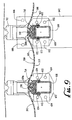
- Figs. 9-14 illustrate an alternate sieve mat 500 having a boltless attachment design.
- the sieve mat 500 comprises mat sections of which sections 508, 510 and 512 are shown in Fig. 9 .
- Each mat section 508, 510, 512 etc. is secured at each tube assembly via the connection mechanism.
- Each of the sieve mat sections 508, 510, 512 etc. is preferably homogenous, uniform, unitary, and one-piece without splices.
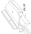
- the mat section may be assembled from multiple pieces such as separately forming the end sections 509a, 509b and attaching them to the central section 509c (see Fig. 13 ).
- a single mat section 508, 510, 512 may be removed for replacement or repair without requiring replacement of remaining sieve mat sections.
- the sieve mat 500 includes perforations along its length (see for example the perforations 503 in mat section 510 of Fig. 9 ), the perforations being of a size and shape so as to permit particles of a given size to pass through for sorting.
- the individual perforations may be tapered and arranged in any suitable pattern and location.
- each mat section is supported by a pair of transverse mat supports, in the illustrated portion for example, the mat section 510 is supported by supports 608, 610.
- the sieve mat supports are in the form of rectangular tubes arranged with the longer sides oriented vertically. Other shapes and orientations for the mat supports or frame tubes may be utilized.
- the sieve mat supports 608, 610 etc. are alternately connected to either the support frame 40 (via connector 642) or to the movable balancer support frame section 655.
- the balancer 655 is supported via shear springs 660 and vertically supported by the vertical stabilizers 620, 630 which were described above in further detail with reference to elements 420 and 430 of Figs. 3-6 .
- Each sieve mat section is connected on one end to a frame tube support and on the other end to a balancer tube support.
- mat section 510 is connected on one end to balancer tube 608 and on the other end to frame tube support 610. The operative functions of these connections will be described in further detail below.
- the frame tube assembly 610 is supported directly to the support frame 40 (as in Figs. 1-2 ) via connector 642.
- the frame tube 610 comprises a rectangular tubing arranged below the sieve mat section 510 extending transversely along the width of the frame assembly.
- the frame tube 610 includes an end flange 650 welded thereon for attachment to the connector 642.
- the connector 642 has four holes which have been drilled and tapped for accepting the bolts 652 which secure the flange 650 onto the connector 642.
- the connector 642 is in turn connected by a series of bolts 646. As shown in Fig.
- the frame tube 610 is directly connected to the support frame 40 at both the lower section 40a and the upper section 40b by a connection through the connector plate 642.
- Other connection mechanisms may be used such as through bolt and nut, welding, rivet, or any suitable fastener.
- the balancer tube 608 and flange 653 are the same configuration as the frame tube 610 and flange 650.
- the balance tube 608 is mounted differently, however, as the flange 653 at the end of the tube 608 is connected to a spacer 651 via bolts 654.
- the spacer 651 in turn is mounted to the balancer 655.
- the balancer 655 is generally the same as the balancer 50 of the previous embodiment but has a curved lower section 655a.
- the mat sections 508, 510, 512 etc. are transversely connected to the respective frame tube on one end and the balancer tube on the other end along the length of the mat section.
- mat section 510 is connected on one end to the frame tube 610 and on the other end to balancer tube 608.
- the frame tube 610 includes a clamp bar assembly 710 that is attached to the tube 610 via bolts 613, 613 on opposite sides of the tube 610.
- the balancer tube 608 includes a clamp bar assembly 740 that is attached to the tube 608 via bolts 612, 612 on opposite sides of the tube 608.
- the clamp bar assemblies 710 and 740 and the mechanisms for clamping the edges of the mat sections thereto are the same. Thus only the clamp bar assembly 710 will be described and should be understood to apply to the clamp bar assembly 740.
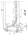
- the clamp bar assembly 710 may be formed in a single piece, but the assembly is preferably formed in a plurality of sections 712, 714, 716, 718 and 720.
- End clamp bar sections 712 and 720 are curved sections, while sections 714, 716 and 718 are straight sections.
- the curved clamp bar sections 712 and 720 are connected to respective gussets 615, 616 attached to the frame tube 610 providing a curved spacer for supporting the curved clamp bar end sections.
- the clamp bar assembly 740 has straight and curved sections, the curved sections being connected to respective gussets 617, 618 attached to the balancer tube 608.
- the clamp bar assembly 710 is preferably formed in sections.
- the curved end sections 712, 720 are identical and have a length of about 13 inches (33 mm).
- the straight sections 714, 718 are identical and have a length of about 16.5 inches (42 mm).
- the center section 716 has a length of about 12 inches (30.5 mm).
- Fig. 12A illustrates a 182.9 cm (6 ft) machine width having two type 1 curved sections 712, 720; two type 2 straight sections 714, 718; and one type 3 straight section 716.
- the clamp bar sections When installed on the frame bar, the clamp bar sections will be preferably be adjacent each other and preferably touching as shown in Fig. 10 .
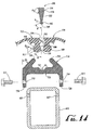
- Figs. 13 and 14 illustrate details of a connection system according to a preferred boltless configuration.
- the clamp bar 714 has a generally H-shape in cross-section with a central bar 725, lower legs 728, 730 and upper arms 723, 724.
- the upper arms 723, 724 extend upwardly and inwardly, and are inwardly angled at an angle ⁇ 1 of about 30°-60°, or preferably about 45°.
- the ends are rounded but may be of other shapes.
- the central bar 725 includes a channel 727 running centrally along its length.
- Each of the clamp assembly sections such as clamp bar section 714 is placed onto the tube 610.
- the tube 610 has a series of tapped holes 607 on each side.
- the clamp section 714 has a U-shaped lower portion comprised of legs 728, 730 that include holes 734, 732 that are aligned with the holes 607 of the tube 610.
- the two elements may then be secured together by bolts 612.
- Each clamp section 712, 714 etc. is attached in similar fashion.
- the clamp bar 714 may be secured by the bolts as illustrated or via clips, adhesive or any other suitable connection mechanism.
- the respective downwardly extending end portions 509, 511 of adjacent sieve mat sections 510, 512 are secured by the clamp bar 714.
- sieve mat end portion 509 of sieve mat sections 510 is secured in clamp bar 714 next to sieve mat end portion 511 of sieve mat section 512.
- the sieve mat end portions 509, 511 are configured to mate with and nest within the clamp bar 714.
- the end portion 511 at its inner surface includes an indentation 530 arranged at an angle ⁇ 2 of about 45° which mates with the upper arm 724 of the clamp bar 714.
- the outer surface also has an indentation 532 forming an angle ⁇ 1 of about 160°.
- the outer surface has an upper lip 534 and a lower lip 536.
- the wedge 550 has side surfaces 552, 554 formed at an outward angle ⁇ 2 for nesting into the indentation 532 of angle ⁇ 1 of the outer surface of sieve mat end 511.
- the lower section of the wedge is tapered (i.e. narrowed) until the wedge bottom is reached.
- the wedge also includes a nipple or retaining ridge 560 at the bottom forming a shoulder or lip 562.
- the wedge 550 is hammered into position; it may be treated/sprayed with a suitable lubricant such as water or silicone spray to facilitate installation.
- a suitable lubricant such as water or silicone spray to facilitate installation.
- the wedge 550 is secured in place by tapered surface 554 below lip 534 and by the shoulder 562 of the nipple 560 below lip 536.
- This shoulder/nipple configuration provides a positive locking mechanism to prevent dislodging of the wedge during operation.
- the shoulder 562 also provides support for the mat sections.
- the wedge 550 itself is inhibited from being over-inserted by the wedge taper 552 contacting the angled outer surface 532 of the end section 511 and by the nipple 560 contacting the bottom of channel 727. As shown in Fig.
- the wedge 550 has a top surface that is flush with the top surfaces of the sieve mat sections 508, 510. Such a flush top surface without any protruding bolts or fasteners eliminates protrusions that may tend to restrict flow.
- the wedge 550 may be formed of one or more pieces, it is preferably constructed as a single piece extending the entire width of the sieve mat section 510. In one configuration, the wedge 550 is slightly longer (e.g. 2.5 cm longer) in width than the sieve mat providing an extension beyond the mat edge creating a gripping surface that can be grabbed and pulled when manually removing sieve mat sections.
- the wedge 550 when the wedge 550 is in place, its top surface is flush with the top surface of the sieve mat sections thereby producing a smooth transition surface that does not inhibit product flow. The flush surface also assists the wedge in avoiding wear from the product flow.
- the channel 727 in the clamp bar provides a gap between the nipple 560 and the clamp bar that permits the wedge nipple 560 to have enough room to be urged downwardly past the bottom edge 536 of the sieve mat end section thereby assisting in wedge insertion.
- the attachment system is comprised of three primary sections, the sectional clamp bar assembly 714, the wedge 550 and the sieve mat 500.
- the preferred material for the sieve mat is polyurethane elastomer with an 85 Shore A hardness.
- a preferred material for the clamp bar 714 and the wedge 550 is also polyurethane, preferably with a 90 Shore A hardness or harder.
- the clamp bar 714 may be made of harder polyurethane material, or other suitable material such as some other plastic. Preferably, the material should be sufficiently stiff and durable, but have some impact resilience.
- the combination provides a polyurethane to polyurethane fit as opposed to polyurethane to metal fit as in other connection systems.
- the wedge 550 may also be made from other materials such as other plastics or rubber.
- the formula of polyurethane for each part within the system is preferably designed to provide the best properties and performance for the required application, taking into consideration the function during equipment operation.
- the manufacturing process for each component may be the same or quite similar.
- One part has flexibility, tensile strength and wear resistance built into its design, while the next part may concentrate on a need for shear strength and impact resistance.
- the polyurethane is preferably formulated to not only take into consideration the performance needs of the operating equipment, but also other environmental criteria that the part may be operating in relating to chemical resistance, temperature conditions and potentially other factors.
- the parts may be made by any suitable method such as casting or injection molding. Casting of the parts is the preferred method of polyurethane manufacturing because of the heavy cross sectional areas that would be prone to sink holes and deformation during the curing process if the parts were injection molded.
- the size of the parts and parting line requirements, multiple axis removal of mold parts through the use of slides, sectional dies, and even a possible need for an elaborate core section in some of the parts would make it very difficult to produce the part via injection molding.
- Injection molds may also require elaborate multiple gating, reservoirs and cooling systems to effectively produce the part.
- An injection molding process may still be subject to potential fit-up issues between components that could result in quality control issues.
- the parts may be made by different processes, such as the sieve mat 500 made by casting, the clamp assembly 700 made by injection molding, and the wedge 550 made by an extrusion process.
- Casting is preferred as being a single process that is generally usable on all three parts.
- it may be preferred to complete the design by secondary machining, cutting or other processing after the initial cast or mold has cured.
- the clamp bar sections 710 are the hardest and most rigid part and may be made by casting, extrusion or injection molding.
- the retaining wedge 550 is somewhat softer and more flexible than the clamp bar parts, but not as resilient and flexible as the sieve mats.
- the retaining wedge 550 may be produced by an extrusion method as an alternative to casting which may allow longer pieces to be made in a single piece.
- the sieve mats are also preferably produced by casting the polyurethane in a desired configuration.
- the specific formulation for the polyurethane of the sieve mat will depend on the application such as whether the mat is used as a flip-flow device or as a conveyor. Flexible strength, elasticity, impact resistance, wear factors, chemical resistance and other physical environment issues are considerations for the polyurethane formulation.
- the central portion of the mat 510 and the end sections 509, 512 are preferably molded/cast as one piece to ensure uniform properties throughout the mat.
- the mat end sections 509, 512 are forced into a tight interference fit by inserting the retaining wedge 550.
- the mat material should be resilient enough to compress into the arms 723, 724 of the clamp bar 714 and follow the curvature of the clamp bar 714, yet still be strong enough to not pull apart in tensile.
- the mats may be cast with a variety of openings or apertures configured for the screening operation being performed. Though casting is a preferred method for producing the mats, they may also be made as blanks without any holes or perforations. Whatever hole configuration is desired for a given screening application, the holes may be formed into the mats in a secondary operation.
- the preferred methods for secondary processing of the mats for hole pattern installation include either water jet cutting or punching or other suitable method.
- the various embodiments disclosed may be combined together or separately utilized.
- the vertical stabilizers and/or the horizontal compression axis shear springs may be used with flexible mat conveyors or screening machines of alternate configurations, including prior art machines;
- the gradually curved lateral side mat systems may be implemented with any of the disclosed flexible mat conveyors or screening machines or separately with alternate machine configurations;
- the boltless mat section attachment systems may be implemented with any of the disclosed flexible mat conveyors or screening machines or separately with alternate machine configurations.
- the boltless clamp system may employ the disclosed wedge design but may utilize alternate wedge configurations and the disclosed wedge design may be implemented into alternate clamp configurations.
Landscapes
- Combined Means For Separation Of Solids (AREA)
Claims (13)
- Eine Siebvorrichtung aufweisend
eine Basis;
eine Rahmenanordnung, welche einen Hauptstützrahmenabschnitt (40) enthält, der an der Basis angebracht ist, und einen bewegbaren Stützrahmenabschnitt (50), welcher bewegbar an dem Hauptstützrahmenabschnitt angebracht ist;
eine Mehrzahl von Siebmattenstützen (302, 304, 306, 308, etc.), die in Querrichtung entlang der Länge der Rahmenanordnung im Abstand zueinander angeordnet sind, wobei die Siebmattenstützen wechselweise mit dem Hauptstützrahmenabschnitt und dem bewegbaren Stützrahmenabschnitt verbunden sind;
eine flexible Siebmatte (200, 500), die eine Mehrzahl von Siebmattenabschnitten (202, 204, 206, 208, etc.) aufweist und sich entlang einer Länge der Rahmenanordnung erstreckt und mit den Siebmattenstützen verbunden ist und von diesen gestützt ist,
ein Antriebssystem (110/116/117), das betreibbar ist, um mindestens eine von einem benachbarten Paar von Siebmattenstützen zu bewegen, sodass wechselweise der Abstand zwischen dem benachbarten Paar von Siebmattenstützen vergrößert und verkleinert wird, wobei der Siebmattenabschnitt wechselweise in einer Spannwellenbewegung gespannt und entspannt wird, wenn der Abstand zwischen dem benachbarten Paar von Siebmatten wechselweise vergrößert und verkleinert wird,
dadurch gekennzeichnet, dass
die Siebmatte nach oben gekrümmte laterale Seiten (200a, 200b) aufweist, die eine graduell gekrümmte Form bilden, wobei die gekrümmte Form an einem Mittelpunkt davon einen Radius R hat von: 15 cm (6 Inches) ≤R ≤ 76 cm (30 Inches); und
die graduell gekrümmte Form vor Erreichen der Vertikale endet, wobei ein oberes Ende (L2) der nach oben gekrümmten lateralen Seiten einen Anstieg von 75% der Vertikale oder weniger hat. - Eine Vorrichtung gemäß Anspruch 1, wobei die nach oben gekrümmten lateralen Seiten der Siebmatte Perforationen (203) zum Sieben von Material aufweisen.
- Eine Vorrichtung gemäß Anspruch 1, wobei die gekrümmte Form einen minimalen Krümmungsradius R von mindestens 30,5 cm (12 Inches) hat.
- Eine Vorrichtung gemäß Anspruch 1, wobei die gekrümmte Form definiert ist durch ein Verhältnis R/M ≥0,2 wobei
R einem Minimalradius der gekrümmten Form entspricht,
M der halben Breite der Siebmatte entspricht. - Eine Vorrichtung gemäß Anspruch 1, wobei eine Hauptebene der Siebmatte und der Rahmenanordnung in einem Deklinationswinkel φ zur Horizontalen von zwischen 5° und 30° angeordnet ist.
- Eine Vorrichtung gemäß Anspruch 5, wobei der Deklinationswinkel über die Länge der Siebmatte variiert, indem er von einem Einlass-Ende zu einem Auslass-Ende abnimmt.
- Eine Vorrichtung gemäß den Ansprüchen 1 bis 6, wobei die Mehrzahl von Siebmattenabschnitten (202, 204, 206, 208, etc.) an den Siebmattenstützen untereinander verbunden sind.
- Eine Vorrichtung gemäß Anspruch 1, wobei die nach oben gekrümmten lateralen Seiten enden, bevor sie die Vertikale erreichen und ein Bogensegment mit einem Krümmungswinkel θ von 70° oder weniger bilden.
- Eine Vorrichtung gemäß Anspruch 1, wobei ein oberes Ende (L2) der gekrümmten Form einen Anstieg β von 67,5° oder weniger hat.
- Ein Materialsiebeverfahren aufweisend die Schritte:Bereitstellen einer Siebmatte (200, 500) mit einer Mehrzahl von Siebmattenabschnitten (202, 204, 206, 208, etc.), die entlang einer Länge einer Siebvorrichtung angeordnet sind, wobei jeder Siebmattenabschnitt in Querrichtung zwischen Rahmenseiten der Siebvorrichtung angeordnet ist und von einem benachbarten Paar von ersten und zweiten Mattenstützen (302, 304, 306, 308, etc.) gestützt wird;Antreiben der Vorrichtung, um mindestens eine der ersten und zweiten Mattenstützen zu bewegen, um wechselweise den Abstand zwischen der ersten und der zweiten Mattenstütze zu vergrößern und zu verkleinern, wobei der Siebmattenabschnitt wechselweise in einer Spannwellenbewegung gespannt und entspannt wird, wenn der Abstand zwischen der ersten und der zweiten Mattenstütze wechselweise vergrößert und verkleinert wird;Anheben lateraler Seiten (200a, 200b) der Siebmattenabschnitte, um graduell gekrümmte Seitenränder auszubilden, wobei die graduell geformten Seitenränder einen minimalen Krümmungsradius R an einem Mittelpunk davon haben von: 15 cm (6 Inches) ≤R ≤ 76 cm (30 Inches) und ein oberes Ende L2 der gekrümmten Seitenränder einen Anstieg von 75% der Vertikalen oder weniger hat.
- Ein Verfahren gemäß Anspruch 10, ferner aufweisend das Anordnen der Siebmatten und Rahmenseiten entlang eines Deklinationswinkels φ zu Horizontale von zwischen ungefähr 5° und 30°, wobei der Deklinationswinkel über die Länge der Siebmatte konstant ist.
- Ein Verfahren gemäß Anspruch 10, ferner aufweisend das Bilden der gekrümmten Seitenränder in einem Bogensegment mit einem Krümmungswinkel θ von 70° oder weniger.
- Ein Verfahren gemäß Anspruch 10, wobei die gekrümmten Seitenränder der Siebmatte Perforationen (203) zum Sieben von Material aufweisen.
Applications Claiming Priority (3)
| Application Number | Priority Date | Filing Date | Title |
|---|---|---|---|
| US10/867,595 US7344032B2 (en) | 2004-06-14 | 2004-06-14 | Flexible sieve mat screening apparatus |
| US11/036,599 US7654394B2 (en) | 2004-06-14 | 2005-01-14 | Flexible mat screening or conveying apparatus |
| PCT/US2005/020796 WO2005123278A2 (en) | 2004-06-14 | 2005-06-13 | Flexible mat screening or conveying apparatus |
Publications (3)
| Publication Number | Publication Date |
|---|---|
| EP1765524A2 EP1765524A2 (de) | 2007-03-28 |
| EP1765524A4 EP1765524A4 (de) | 2010-09-29 |
| EP1765524B1 true EP1765524B1 (de) | 2016-06-01 |
Family
ID=35510295
Family Applications (1)
| Application Number | Title | Priority Date | Filing Date |
|---|---|---|---|
| EP05761840.7A Expired - Lifetime EP1765524B1 (de) | 2004-06-14 | 2005-06-13 | Siebeinrichtung und verfahren mit flexibler matte |
Country Status (4)
| Country | Link |
|---|---|
| US (1) | US7654394B2 (de) |
| EP (1) | EP1765524B1 (de) |
| CA (2) | CA2802930C (de) |
| WO (1) | WO2005123278A2 (de) |
Families Citing this family (42)
| Publication number | Priority date | Publication date | Assignee | Title |
|---|---|---|---|---|
| GB0603246D0 (en) | 2006-02-17 | 2006-03-29 | Genesis Fluid Solutions Llc | Duct for use in an apparatus for separating suspended solid from water and a method feeding water having suspended solid |
| US7578394B2 (en) * | 2007-03-21 | 2009-08-25 | Derrick Corporation | Method and apparatuses for screening |
| SE535643C2 (sv) * | 2010-03-03 | 2012-10-30 | Sandvik Intellectual Property | Förfarande för tillverkning av siktmedia innehållande kolfibrer |
| SE534710C2 (sv) * | 2010-03-03 | 2011-11-29 | Sandvik Intellectual Property | Vibrationssikt med modulär siktmedia |
| US10441906B2 (en) * | 2011-07-08 | 2019-10-15 | M-I L.L.C. | Compound angle wedge screen clamp for vibratory separator |
| US9427780B2 (en) * | 2011-10-26 | 2016-08-30 | Rejean Houle | Vibrating slot sieve slurry processing apparatus and method |
| US8757392B2 (en) | 2011-11-23 | 2014-06-24 | Action Vibratory Equipment, Inc. | Flexible mat screening apparatus with offset supports |
| US10576502B2 (en) | 2012-05-25 | 2020-03-03 | Derrick Corporation | Injection molded screening apparatuses and methods |
| EP3482839A1 (de) * | 2012-05-25 | 2019-05-15 | Derrick Corporation | Spritzgegossene siebanordnung und verfahren |
| US9409209B2 (en) | 2012-05-25 | 2016-08-09 | Derrick Corporation | Injection molded screening apparatuses and methods |
| US11161150B2 (en) | 2012-05-25 | 2021-11-02 | Derrick Corporation | Injection molded screening apparatuses and methods |
| HK1213219A1 (zh) * | 2012-10-16 | 2016-06-30 | Derrick Corporation | 用於篩選的方法和設備 |
| CN104056774B (zh) * | 2013-03-18 | 2017-05-31 | 宾德股份公司 | 具有连杆覆盖装置的筛分机 |
| US9258945B2 (en) * | 2013-09-20 | 2016-02-16 | Deere & Company | Hanger mount for a reciprocating sieve |
| US9226450B2 (en) * | 2013-09-20 | 2016-01-05 | Deere & Company | Lightweight hybrid material reciprocating sieve |
| US9198359B2 (en) * | 2013-09-20 | 2015-12-01 | Deere & Company | Frame for a reciprocating sieve |
| AU2013245556B2 (en) * | 2013-10-20 | 2016-03-10 | Vibfem Pty Ltd | New Flip-Flow screen design which will allow better screen reliability and effectiveness |
| EP2926916A1 (de) * | 2014-04-03 | 2015-10-07 | IFE Aufbereitungstechnik Gmbh | Seitenabdichtung für ein Spannwellensieb |
| CN104028455A (zh) * | 2014-05-30 | 2014-09-10 | 浙江立鑫高温耐火材料有限公司 | 一种振动筛 |
| WO2016016322A1 (en) * | 2014-07-31 | 2016-02-04 | Eurogomma Di Annoni Luciano | Screening apparatus and method of modifying a screening apparatus |
| KR101633419B1 (ko) * | 2015-12-21 | 2016-06-24 | 주식회사 초당산업 | 가변진동발생기를 이용한 골재선별장치 및 이를 이용한 골재생산방법 |
| KR101633417B1 (ko) * | 2015-12-21 | 2016-06-24 | 주식회사 초당산업 | 선별장치용 진동스크린 및 이를 구비한 골재선별장치 |
| CN105457885A (zh) * | 2016-01-22 | 2016-04-06 | 安徽捷迅光电技术有限公司 | 一种物料筛选装置 |
| DE102016103803B4 (de) * | 2016-03-03 | 2018-07-26 | Spaleck GmbH & Co. Kommanditgesellschaft | Schwingförderer mit einem durch eine flexible Matte gebildeten Fördertrog |
| DE102016011817A1 (de) * | 2016-10-05 | 2018-04-05 | Hein, Lehmann Gmbh | Spannwellensiebmaschine mit optimierter Siebbelagbefestigung |
| CN116273870A (zh) | 2017-04-28 | 2023-06-23 | 德里克公司 | 热塑组合物、方法、装置和用途 |
| US11505638B2 (en) | 2017-04-28 | 2022-11-22 | Derrick Corporation | Thermoplastic compositions, methods, apparatus, and uses |
| DE102017112108B3 (de) | 2017-06-01 | 2018-02-22 | Spaleck GmbH & Co. Kommanditgesellschaft | Siebvorrichtung mit Querträgern und daran angebrachten Siebmatten |
| US11213857B2 (en) | 2017-06-06 | 2022-01-04 | Derrick Corporation | Method and apparatus for screening |
| BR112019025843A2 (pt) | 2017-06-06 | 2020-07-14 | Derrick Corporation | método e aparelhos para peneiramento |
| CN107185823B (zh) * | 2017-06-12 | 2019-03-22 | 东北大学 | 一种双机驱动亚共振自同步振动弛张筛 |
| JP7122113B2 (ja) * | 2017-12-27 | 2022-08-19 | ニチハ株式会社 | 建材製造装置および建材製造方法 |
| AU2019232790B2 (en) * | 2018-09-17 | 2025-03-13 | Lettela Pty Limited | Screen panel locking system |
| CN110369111A (zh) * | 2019-08-22 | 2019-10-25 | 詹赛红 | 一种道路铺设用碎石筛选装置 |
| CN112221931B (zh) * | 2020-09-24 | 2021-06-25 | 江苏绿博生物科技有限公司 | 一种采用回转式滚筒筛网的打浆分选一体机 |
| CN112934689A (zh) * | 2021-01-26 | 2021-06-11 | 江西同建机械发展有限公司 | 一种石油化工用筛板机构 |
| DE102022103295A1 (de) | 2022-02-11 | 2023-08-17 | Haver NIAGARA GmbH | Siebmaschine mit einsteckbaren Siebbodenelementen |
| CN115286416B (zh) * | 2022-08-12 | 2023-06-09 | 浙江精瓷半导体有限责任公司 | 一种陶瓷制冷片的生产工艺 |
| KR102590159B1 (ko) | 2022-12-21 | 2023-10-17 | 삼영플랜트 주식회사 | 골재의 입도선별용 가변형 진동스크린 |
| EP4417326A1 (de) * | 2023-02-16 | 2024-08-21 | Schenck Process Australia Pty Limited | Punktmagnetische befestigung für modulare screening-medien |
| CN118304989B (zh) * | 2024-06-07 | 2024-08-30 | 湖南领航新材料有限公司 | 一种高岭土湿法精炼用的分离设备 |
| CN118635106B (zh) * | 2024-08-14 | 2024-10-25 | 新乡市伟良筛分机械有限公司 | 一种具有自动顶框机构的摇摆筛 |
Citations (2)
| Publication number | Priority date | Publication date | Assignee | Title |
|---|---|---|---|---|
| AT2993B (de) * | 1899-10-05 | 1900-12-10 | Muehlenbauanstalt Und Maschinenfabrik Vorm Gebr Seck | Flachsieb mit Vorrichtung zum Abklopfen der Bespannung. |
| GB1463491A (en) * | 1974-04-04 | 1977-02-02 | Ter Hart B J A | Strainer particularly for use in a slaughter-house |
Family Cites Families (41)
| Publication number | Priority date | Publication date | Assignee | Title |
|---|---|---|---|---|
| US1725511A (en) * | 1926-02-12 | 1929-08-20 | Richard A Leahy | Apparatus for screening granular materials |
| US2230321A (en) * | 1939-02-23 | 1941-02-04 | Downs Henry William | Pulp screen |
| US2338904A (en) * | 1940-04-11 | 1944-01-11 | Cowles Co | Apparatus for screening paper pulp |
| US2329773A (en) * | 1941-05-31 | 1943-09-21 | Richard A Leahy | Vibrating screen |
| US3219065A (en) * | 1962-10-22 | 1965-11-23 | Goodman Mfg Co | Adjustable screen cloth stretcher |
| DE1204920B (de) * | 1963-01-05 | 1965-11-11 | Albert Wehner | Sieb- oder Foerdermaschine |
| DE1206372B (de) * | 1964-09-26 | 1965-12-09 | Albert Wehner | Siebrost |
| DE1275339B (de) * | 1967-07-13 | 1968-08-14 | Albert Wehner | Siebmaschine |
| DE2108924A1 (en) | 1971-02-25 | 1972-09-07 | Wehner, Albert, 7881 Wieladingen | Flexible sieve edge seal - of bellows type wall prevents edge spillage |
| US4064051A (en) | 1972-06-02 | 1977-12-20 | Hein, Lehmann Akt. | Elastic transporting, sieving or filtering base with swinging drive |
| US4188288A (en) * | 1972-11-30 | 1980-02-12 | Hein, Lehmann Ag | Screen with tubular frame systems coupled for rectilinear motion |
| US3971715A (en) * | 1973-02-27 | 1976-07-27 | Albert Wehner | Device for sieving, sorting, filtering and the like |
| US4065051A (en) * | 1976-07-01 | 1977-12-27 | Jones Frederick J | Refuse container |
| DE2813630A1 (de) * | 1978-03-30 | 1979-10-04 | Hein Lehmann Ag | Seitenabdichtung fuer eine siebmaschine |
| DE3139279A1 (de) | 1981-10-02 | 1983-04-21 | Klöckner-Humboldt-Deutz AG, 5000 Köln | Schwingmaschine zum sieben und/oder foerdern, insbesondere einmassen-freischwinger-maschine |
| US4482046A (en) * | 1982-04-15 | 1984-11-13 | General Kinematics Corporation | Flexible trough vibratory conveyor |
| US4632751A (en) * | 1982-11-15 | 1986-12-30 | Johnson Louis W | Shaker screen |
| DE3307916A1 (de) * | 1983-03-05 | 1984-09-06 | Hein, Lehmann AG, 4000 Düsseldorf | Siebbelag mit auswechselbaren siebelementen |
| US4757664A (en) * | 1985-06-04 | 1988-07-19 | Screenex Wire Weaving Manufacturers (Proprietary) Limited | Wear resistant panel arrangement |
| DE3521753A1 (de) | 1985-06-18 | 1986-12-18 | Hein, Lehmann AG, 4000 Düsseldorf | Siebmaschine mit einem an querelementen befestigten siebbelag |
| DE3524895C1 (de) * | 1985-07-12 | 1986-12-18 | Hein, Lehmann AG, 4000 Düsseldorf | Siebmaschine |
| DE3526767A1 (de) | 1985-07-26 | 1987-01-29 | Hein Lehmann Ag | Abdichtung fuer eine siebmaschine |
| AT386969B (de) * | 1987-02-05 | 1988-11-10 | Ife Gmbh | Seitenabdichtung fuer siebvorrichtungen |
| AT386137B (de) | 1987-02-23 | 1988-07-11 | Binder Co Ag | Siebmaschinenabdichtung |
| AT387342B (de) | 1987-08-07 | 1989-01-10 | Binder Co Ag | Siebmaschinenabdichtung |
| AT390898B (de) * | 1988-09-05 | 1990-07-10 | Ife Gmbh | Siebvorrichtung |
| AT393636B (de) * | 1989-07-21 | 1991-11-25 | Binder Co Ag | Siebvorrichtung mit beweglichen, verformbaren sieben |
| SE507468C2 (sv) * | 1993-05-10 | 1998-06-08 | Svedala Arbra Ab | Vibrationssikt |
| DE9315227U1 (de) * | 1993-10-08 | 1994-01-05 | Ife Industrie-Einrichtungen Fertigungs-Aktiengesellschaft, Waidhofen | Seitenabdichtung für Siebvorrichtungen |
| US5595306A (en) * | 1995-05-22 | 1997-01-21 | Emerson Electric Co. | Screening system |
| US5816413A (en) * | 1995-09-08 | 1998-10-06 | W.S. Tyler, Canada | Wire screen deck having replaceable modular screen panels |
| US5746322A (en) * | 1996-07-02 | 1998-05-05 | Action Equipment Co., Inc. | Vibratory finger screen with lateral wedge members |
| AUPO213796A0 (en) * | 1996-09-05 | 1996-09-26 | Lettela Proprietary Limited | Modular screen panel |
| US5944170A (en) * | 1997-05-01 | 1999-08-31 | Laveine; Andrew T. | Stroke control system for a vibratory conveyor |
| US6179128B1 (en) * | 1998-10-02 | 2001-01-30 | Tuboscope I/P, Inc. | Tension clamp and screen system |
| US6669027B1 (en) * | 1999-03-19 | 2003-12-30 | Derrick Manufacturing Corporation | Vibratory screening machine and vibratory screen and screen tensioning structure |
| DE10028778A1 (de) * | 2000-06-15 | 2002-01-31 | Claas Selbstfahr Erntemasch | Abscheidevorrichtung bei Mähdreschern |
| AUPQ931100A0 (en) * | 2000-08-09 | 2000-08-31 | Ludowici Mineral Processing Equipment Pty Ltd | Screening apparatus |
| US6659286B2 (en) * | 2001-10-05 | 2003-12-09 | Varco I/P, Inc. | Drawbar and screen system |
| AUPR869701A0 (en) * | 2001-11-06 | 2001-11-29 | Usf Johnson Screens Pty Ltd | Screening panel securing system |
| US7175027B2 (en) * | 2002-01-23 | 2007-02-13 | Varco I/P, Inc. | Shaker screen and clamping system |
-
2005
- 2005-01-14 US US11/036,599 patent/US7654394B2/en active Active
- 2005-06-13 WO PCT/US2005/020796 patent/WO2005123278A2/en not_active Ceased
- 2005-06-13 CA CA2802930A patent/CA2802930C/en not_active Expired - Lifetime
- 2005-06-13 EP EP05761840.7A patent/EP1765524B1/de not_active Expired - Lifetime
- 2005-06-13 CA CA2569471A patent/CA2569471C/en not_active Expired - Lifetime
Patent Citations (2)
| Publication number | Priority date | Publication date | Assignee | Title |
|---|---|---|---|---|
| AT2993B (de) * | 1899-10-05 | 1900-12-10 | Muehlenbauanstalt Und Maschinenfabrik Vorm Gebr Seck | Flachsieb mit Vorrichtung zum Abklopfen der Bespannung. |
| GB1463491A (en) * | 1974-04-04 | 1977-02-02 | Ter Hart B J A | Strainer particularly for use in a slaughter-house |
Also Published As
| Publication number | Publication date |
|---|---|
| US20050274653A1 (en) | 2005-12-15 |
| CA2802930C (en) | 2014-08-26 |
| US7654394B2 (en) | 2010-02-02 |
| CA2802930A1 (en) | 2005-12-29 |
| WO2005123278A3 (en) | 2007-12-13 |
| CA2569471A1 (en) | 2005-12-29 |
| EP1765524A4 (de) | 2010-09-29 |
| WO2005123278A2 (en) | 2005-12-29 |
| EP1765524A2 (de) | 2007-03-28 |
| CA2569471C (en) | 2013-05-28 |
Similar Documents
| Publication | Publication Date | Title |
|---|---|---|
| CA2802930C (en) | Flexible mat screening or conveying apparatus | |
| US7344032B2 (en) | Flexible sieve mat screening apparatus | |
| EP2782683B1 (de) | Flexible mattensiebvorrichtung mit versetzten stützen | |
| AU2021250991B2 (en) | Apparatuses, methods, and systems for vibratory screening | |
| US7942272B2 (en) | Screen system | |
| AU2002321447B2 (en) | Screen system | |
| CN1181932C (zh) | 筛选装置 | |
| US11731167B2 (en) | Apparatuses, methods, and systems for vibratory screening | |
| AU2002321447A1 (en) | Screen system | |
| US11806755B2 (en) | Apparatuses, methods, and systems for vibratory screening | |
| CA3145292C (en) | Apparatuses, methods, and systems for vibratory screening | |
| WO2023009214A1 (en) | Apparatuses, methods, and systems for vibratory screening | |
| TR2021015093A2 (tr) | Titreşimli eleme için düzenekler, usuller ve sistemler. | |
| EA043698B1 (ru) | Устройство, способ и система для вибрационного просеивания |
Legal Events
| Date | Code | Title | Description |
|---|---|---|---|
| PUAI | Public reference made under article 153(3) epc to a published international application that has entered the european phase |
Free format text: ORIGINAL CODE: 0009012 |
|
| 17P | Request for examination filed |
Effective date: 20070112 |
|
| AK | Designated contracting states |
Kind code of ref document: A2 Designated state(s): AT BE BG CH CY CZ DE DK EE ES FI FR GB GR HU IE IS IT LI LT LU MC NL PL PT RO SE SI SK TR |
|
| AX | Request for extension of the european patent |
Extension state: AL BA HR LV MK YU |
|
| DAX | Request for extension of the european patent (deleted) | ||
| PUAK | Availability of information related to the publication of the international search report |
Free format text: ORIGINAL CODE: 0009015 |
|
| A4 | Supplementary search report drawn up and despatched |
Effective date: 20100830 |
|
| RIC1 | Information provided on ipc code assigned before grant |
Ipc: B07B 1/28 20060101ALI20100824BHEP Ipc: B07B 1/46 20060101AFI20100824BHEP |
|
| 17Q | First examination report despatched |
Effective date: 20120412 |
|
| GRAP | Despatch of communication of intention to grant a patent |
Free format text: ORIGINAL CODE: EPIDOSNIGR1 |
|
| INTG | Intention to grant announced |
Effective date: 20151223 |
|
| GRAS | Grant fee paid |
Free format text: ORIGINAL CODE: EPIDOSNIGR3 |
|
| GRAA | (expected) grant |
Free format text: ORIGINAL CODE: 0009210 |
|
| AK | Designated contracting states |
Kind code of ref document: B1 Designated state(s): AT BE BG CH CY CZ DE DK EE ES FI FR GB GR HU IE IS IT LI LT LU MC NL PL PT RO SE SI SK TR |
|
| REG | Reference to a national code |
Ref country code: GB Ref legal event code: FG4D |
|
| REG | Reference to a national code |
Ref country code: CH Ref legal event code: EP Ref country code: AT Ref legal event code: REF Ref document number: 803538 Country of ref document: AT Kind code of ref document: T Effective date: 20160615 |
|
| REG | Reference to a national code |
Ref country code: IE Ref legal event code: FG4D |
|
| REG | Reference to a national code |
Ref country code: DE Ref legal event code: R096 Ref document number: 602005049463 Country of ref document: DE |
|
| REG | Reference to a national code |
Ref country code: FR Ref legal event code: PLFP Year of fee payment: 12 |
|
| REG | Reference to a national code |
Ref country code: LT Ref legal event code: MG4D |
|
| REG | Reference to a national code |
Ref country code: NL Ref legal event code: MP Effective date: 20160601 |
|
| PG25 | Lapsed in a contracting state [announced via postgrant information from national office to epo] |
Ref country code: FI Free format text: LAPSE BECAUSE OF FAILURE TO SUBMIT A TRANSLATION OF THE DESCRIPTION OR TO PAY THE FEE WITHIN THE PRESCRIBED TIME-LIMIT Effective date: 20160601 Ref country code: LT Free format text: LAPSE BECAUSE OF FAILURE TO SUBMIT A TRANSLATION OF THE DESCRIPTION OR TO PAY THE FEE WITHIN THE PRESCRIBED TIME-LIMIT Effective date: 20160601 |
|
| PG25 | Lapsed in a contracting state [announced via postgrant information from national office to epo] |
Ref country code: GR Free format text: LAPSE BECAUSE OF FAILURE TO SUBMIT A TRANSLATION OF THE DESCRIPTION OR TO PAY THE FEE WITHIN THE PRESCRIBED TIME-LIMIT Effective date: 20160902 Ref country code: SE Free format text: LAPSE BECAUSE OF FAILURE TO SUBMIT A TRANSLATION OF THE DESCRIPTION OR TO PAY THE FEE WITHIN THE PRESCRIBED TIME-LIMIT Effective date: 20160601 Ref country code: ES Free format text: LAPSE BECAUSE OF FAILURE TO SUBMIT A TRANSLATION OF THE DESCRIPTION OR TO PAY THE FEE WITHIN THE PRESCRIBED TIME-LIMIT Effective date: 20160601 Ref country code: NL Free format text: LAPSE BECAUSE OF FAILURE TO SUBMIT A TRANSLATION OF THE DESCRIPTION OR TO PAY THE FEE WITHIN THE PRESCRIBED TIME-LIMIT Effective date: 20160601 |
|
| PG25 | Lapsed in a contracting state [announced via postgrant information from national office to epo] |
Ref country code: BE Free format text: LAPSE BECAUSE OF NON-PAYMENT OF DUE FEES Effective date: 20160630 |
|
| PG25 | Lapsed in a contracting state [announced via postgrant information from national office to epo] |
Ref country code: RO Free format text: LAPSE BECAUSE OF FAILURE TO SUBMIT A TRANSLATION OF THE DESCRIPTION OR TO PAY THE FEE WITHIN THE PRESCRIBED TIME-LIMIT Effective date: 20160601 Ref country code: IT Free format text: LAPSE BECAUSE OF FAILURE TO SUBMIT A TRANSLATION OF THE DESCRIPTION OR TO PAY THE FEE WITHIN THE PRESCRIBED TIME-LIMIT Effective date: 20160601 Ref country code: EE Free format text: LAPSE BECAUSE OF FAILURE TO SUBMIT A TRANSLATION OF THE DESCRIPTION OR TO PAY THE FEE WITHIN THE PRESCRIBED TIME-LIMIT Effective date: 20160601 Ref country code: CZ Free format text: LAPSE BECAUSE OF FAILURE TO SUBMIT A TRANSLATION OF THE DESCRIPTION OR TO PAY THE FEE WITHIN THE PRESCRIBED TIME-LIMIT Effective date: 20160601 Ref country code: SK Free format text: LAPSE BECAUSE OF FAILURE TO SUBMIT A TRANSLATION OF THE DESCRIPTION OR TO PAY THE FEE WITHIN THE PRESCRIBED TIME-LIMIT Effective date: 20160601 Ref country code: IS Free format text: LAPSE BECAUSE OF FAILURE TO SUBMIT A TRANSLATION OF THE DESCRIPTION OR TO PAY THE FEE WITHIN THE PRESCRIBED TIME-LIMIT Effective date: 20161001 |
|
| REG | Reference to a national code |
Ref country code: CH Ref legal event code: PL |
|
| PG25 | Lapsed in a contracting state [announced via postgrant information from national office to epo] |
Ref country code: PL Free format text: LAPSE BECAUSE OF FAILURE TO SUBMIT A TRANSLATION OF THE DESCRIPTION OR TO PAY THE FEE WITHIN THE PRESCRIBED TIME-LIMIT Effective date: 20160601 Ref country code: PT Free format text: LAPSE BECAUSE OF FAILURE TO SUBMIT A TRANSLATION OF THE DESCRIPTION OR TO PAY THE FEE WITHIN THE PRESCRIBED TIME-LIMIT Effective date: 20161003 Ref country code: BE Free format text: LAPSE BECAUSE OF FAILURE TO SUBMIT A TRANSLATION OF THE DESCRIPTION OR TO PAY THE FEE WITHIN THE PRESCRIBED TIME-LIMIT Effective date: 20160601 |
|
| REG | Reference to a national code |
Ref country code: DE Ref legal event code: R097 Ref document number: 602005049463 Country of ref document: DE |
|
| REG | Reference to a national code |
Ref country code: IE Ref legal event code: MM4A |
|
| PG25 | Lapsed in a contracting state [announced via postgrant information from national office to epo] |
Ref country code: MC Free format text: LAPSE BECAUSE OF FAILURE TO SUBMIT A TRANSLATION OF THE DESCRIPTION OR TO PAY THE FEE WITHIN THE PRESCRIBED TIME-LIMIT Effective date: 20160601 |
|
| PLBE | No opposition filed within time limit |
Free format text: ORIGINAL CODE: 0009261 |
|
| STAA | Information on the status of an ep patent application or granted ep patent |
Free format text: STATUS: NO OPPOSITION FILED WITHIN TIME LIMIT |
|
| PG25 | Lapsed in a contracting state [announced via postgrant information from national office to epo] |
Ref country code: CH Free format text: LAPSE BECAUSE OF NON-PAYMENT OF DUE FEES Effective date: 20160630 Ref country code: LI Free format text: LAPSE BECAUSE OF NON-PAYMENT OF DUE FEES Effective date: 20160630 |
|
| 26N | No opposition filed |
Effective date: 20170302 |
|
| PG25 | Lapsed in a contracting state [announced via postgrant information from national office to epo] |
Ref country code: SI Free format text: LAPSE BECAUSE OF FAILURE TO SUBMIT A TRANSLATION OF THE DESCRIPTION OR TO PAY THE FEE WITHIN THE PRESCRIBED TIME-LIMIT Effective date: 20160601 Ref country code: DK Free format text: LAPSE BECAUSE OF FAILURE TO SUBMIT A TRANSLATION OF THE DESCRIPTION OR TO PAY THE FEE WITHIN THE PRESCRIBED TIME-LIMIT Effective date: 20160601 Ref country code: IE Free format text: LAPSE BECAUSE OF NON-PAYMENT OF DUE FEES Effective date: 20160613 |
|
| REG | Reference to a national code |
Ref country code: FR Ref legal event code: PLFP Year of fee payment: 13 |
|
| PG25 | Lapsed in a contracting state [announced via postgrant information from national office to epo] |
Ref country code: HU Free format text: LAPSE BECAUSE OF FAILURE TO SUBMIT A TRANSLATION OF THE DESCRIPTION OR TO PAY THE FEE WITHIN THE PRESCRIBED TIME-LIMIT; INVALID AB INITIO Effective date: 20050613 Ref country code: CY Free format text: LAPSE BECAUSE OF FAILURE TO SUBMIT A TRANSLATION OF THE DESCRIPTION OR TO PAY THE FEE WITHIN THE PRESCRIBED TIME-LIMIT Effective date: 20160601 |
|
| REG | Reference to a national code |
Ref country code: FR Ref legal event code: PLFP Year of fee payment: 14 |
|
| PG25 | Lapsed in a contracting state [announced via postgrant information from national office to epo] |
Ref country code: TR Free format text: LAPSE BECAUSE OF FAILURE TO SUBMIT A TRANSLATION OF THE DESCRIPTION OR TO PAY THE FEE WITHIN THE PRESCRIBED TIME-LIMIT Effective date: 20160601 Ref country code: LU Free format text: LAPSE BECAUSE OF NON-PAYMENT OF DUE FEES Effective date: 20160613 |
|
| PG25 | Lapsed in a contracting state [announced via postgrant information from national office to epo] |
Ref country code: BG Free format text: LAPSE BECAUSE OF FAILURE TO SUBMIT A TRANSLATION OF THE DESCRIPTION OR TO PAY THE FEE WITHIN THE PRESCRIBED TIME-LIMIT Effective date: 20160601 |
|
| REG | Reference to a national code |
Ref country code: AT Ref legal event code: UEP Ref document number: 803538 Country of ref document: AT Kind code of ref document: T Effective date: 20160601 |
|
| REG | Reference to a national code |
Ref country code: FR Ref legal event code: PLFP Year of fee payment: 19 |
|
| PGFP | Annual fee paid to national office [announced via postgrant information from national office to epo] |
Ref country code: GB Payment date: 20240402 Year of fee payment: 20 |
|
| PGFP | Annual fee paid to national office [announced via postgrant information from national office to epo] |
Ref country code: DE Payment date: 20240328 Year of fee payment: 20 |
|
| PGFP | Annual fee paid to national office [announced via postgrant information from national office to epo] |
Ref country code: AT Payment date: 20240529 Year of fee payment: 20 |
|
| PGFP | Annual fee paid to national office [announced via postgrant information from national office to epo] |
Ref country code: FR Payment date: 20240408 Year of fee payment: 20 |
|
| REG | Reference to a national code |
Ref country code: DE Ref legal event code: R071 Ref document number: 602005049463 Country of ref document: DE |
|
| REG | Reference to a national code |
Ref country code: GB Ref legal event code: PE20 Expiry date: 20250612 |
|
| PG25 | Lapsed in a contracting state [announced via postgrant information from national office to epo] |
Ref country code: GB Free format text: LAPSE BECAUSE OF EXPIRATION OF PROTECTION Effective date: 20250612 |