EP1765546B1 - Système d"équilibrage optique pour machines-outils - Google Patents
Système d"équilibrage optique pour machines-outils Download PDFInfo
- Publication number
- EP1765546B1 EP1765546B1 EP20050758664 EP05758664A EP1765546B1 EP 1765546 B1 EP1765546 B1 EP 1765546B1 EP 20050758664 EP20050758664 EP 20050758664 EP 05758664 A EP05758664 A EP 05758664A EP 1765546 B1 EP1765546 B1 EP 1765546B1
- Authority
- EP
- European Patent Office
- Prior art keywords
- emitting device
- optical
- alignment system
- optical emitting
- lateral arm
- Prior art date
- Legal status (The legal status is an assumption and is not a legal conclusion. Google has not performed a legal analysis and makes no representation as to the accuracy of the status listed.)
- Expired - Lifetime
Links
Images


Classifications
-
- B—PERFORMING OPERATIONS; TRANSPORTING
- B23—MACHINE TOOLS; METAL-WORKING NOT OTHERWISE PROVIDED FOR
- B23D—PLANING; SLOTTING; SHEARING; BROACHING; SAWING; FILING; SCRAPING; LIKE OPERATIONS FOR WORKING METAL BY REMOVING MATERIAL, NOT OTHERWISE PROVIDED FOR
- B23D59/00—Accessories specially designed for sawing machines or sawing devices
- B23D59/001—Measuring or control devices, e.g. for automatic control of work feed pressure on band saw blade
- B23D59/002—Measuring or control devices, e.g. for automatic control of work feed pressure on band saw blade for the position of the saw blade
- B23D59/003—Indicating the cutting plane on the workpiece, e.g. by projecting a laser beam
-
- B—PERFORMING OPERATIONS; TRANSPORTING
- B23—MACHINE TOOLS; METAL-WORKING NOT OTHERWISE PROVIDED FOR
- B23Q—DETAILS, COMPONENTS, OR ACCESSORIES FOR MACHINE TOOLS, e.g. ARRANGEMENTS FOR COPYING OR CONTROLLING; MACHINE TOOLS IN GENERAL CHARACTERISED BY THE CONSTRUCTION OF PARTICULAR DETAILS OR COMPONENTS; COMBINATIONS OR ASSOCIATIONS OF METAL-WORKING MACHINES, NOT DIRECTED TO A PARTICULAR RESULT
- B23Q17/00—Arrangements for observing, indicating or measuring on machine tools
- B23Q17/24—Arrangements for observing, indicating or measuring on machine tools using optics or electromagnetic waves
- B23Q17/2404—Arrangements for improving direct observation of the working space, e.g. using mirrors or lamps
-
- Y—GENERAL TAGGING OF NEW TECHNOLOGICAL DEVELOPMENTS; GENERAL TAGGING OF CROSS-SECTIONAL TECHNOLOGIES SPANNING OVER SEVERAL SECTIONS OF THE IPC; TECHNICAL SUBJECTS COVERED BY FORMER USPC CROSS-REFERENCE ART COLLECTIONS [XRACs] AND DIGESTS
- Y10—TECHNICAL SUBJECTS COVERED BY FORMER USPC
- Y10T—TECHNICAL SUBJECTS COVERED BY FORMER US CLASSIFICATION
- Y10T83/00—Cutting
- Y10T83/828—With illuminating or viewing means for work
-
- Y—GENERAL TAGGING OF NEW TECHNOLOGICAL DEVELOPMENTS; GENERAL TAGGING OF CROSS-SECTIONAL TECHNOLOGIES SPANNING OVER SEVERAL SECTIONS OF THE IPC; TECHNICAL SUBJECTS COVERED BY FORMER USPC CROSS-REFERENCE ART COLLECTIONS [XRACs] AND DIGESTS
- Y10—TECHNICAL SUBJECTS COVERED BY FORMER USPC
- Y10T—TECHNICAL SUBJECTS COVERED BY FORMER US CLASSIFICATION
- Y10T83/00—Cutting
- Y10T83/828—With illuminating or viewing means for work
- Y10T83/839—Mirror or lens
Definitions
- the present invention relates generally to accessories for power tools, and more particularly to a system for providing adjustable optical alignment for power tools.
- a fence may be employed to position a workpiece so that a kerf or channel may be formed in a desired location within the workpiece.
- use of the fence is limited by the requirement of continual resetting and the ability to adjust the fence smoothly or accurately.
- a tool which slides into a slot formed within a power tool such as a table saw, router table, band saw, and the like is often utilized to make square or angled cuts.
- a miter gauge which may be adjusted to different angles may be employed to guide a workpiece past the saw blade.
- a user is often required to perform a number of test cuts prior to arriving at the proper setting of the miter gauge. The requirement of multiple test cuts is not only tedious, but filled with imprecision.
- DE 3406904 discloses an apparatus according to the preamble of claim 1.
- an optical alignment system according to claim 1.
- the optical emitting device is a laser such as a helium-neon laser.
- the horizontal platform is configured to be positioned within a slot defined within the workpiece surface area.
- more than one housing may be employed to house the laser.
- a first laser housing may be included to substantially enclose the laser and to protect the laser from dust and debris.
- a second laser housing may be included to allow the first laser housing including the laser to be secured to the lateral arm.
- the second laser housing may include a recess constructed to receive the first laser housing and an aperture formed within one end of the second laser housing allowing the second laser housing to be coupled to the lateral arm.
- FIG. 1 is an isometric view of a table saw in accordance with an exemplary embodiment of the present invention, wherein the table saw includes an adjustable optical alignment system;
- FIG. 2 is a cross-sectional side view of an optical alignment system in accordance with an exemplary embodiment of the present invention, wherein the optical alignment system is cantilever above a work surface area;
- FIG. 3 is a partial isometric view of an optical alignment system in accordance with an exemplary embodiment of the present invention, wherein the optical alignment system is mounted to a workbench and is directing a light beam onto the cutting path; and
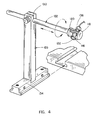
- FIG. 4 is a partial exploded view of an optical alignment system in accordance with an exemplary embodiment of the present invention, wherein the optical alignment system includes adjustment and position locking capabilities.
- a table saw assembly 100 in accordance with the present invention in which such assembly includes an optical alignment system 102 is provided.
- the table saw assembly 100 includes a first slot 104 and a second T-slot 106 generally provided for accepting a miter guide.
- the first T-slot 104 and the second T-slot 106 extend parallel to a saw blade 110 included with the table saw assembly 100.
- the optical alignment system 102 may be secured within one of the T-slots (e.g., the first T-slot 104 or the second T-slot 106) to provide a line-of-cut indicator to a work surface.
- optical alignment system 102 is illustrated with a table saw; it is contemplated that such system 102 may also be used with other power tools such as bandsaws, drill presses, shapers, panel saws, and the like. It is further contemplated that the slot shape may be varied to accept varied shaped guides. In addition, such system may be particularly useful for use with tools in which the workpiece is manipulated with respect to a working element.
- the optical alignment system 102 includes a light source 112 for projecting a beam of visible light onto a workpiece.
- the light source 112 is a coherent light source such as a laser, for example, a HeNe laser, a diode laser and the like.
- An HeNe laser may be advantageous for it generates a highly visible indicator under most situations while requiring a minimal amount of power in comparison with other lasers.
- the light source 112 is channeled into a beam which may be projected as a solid, dashed, or dotted line, an arrow, or the like may attenuate along a non-linear path, depending upon the preference of the operator. For example, upon activation the light source 112 directs a beam of light 114 onto the cutting path of the blade, providing accurate line-of-cut indication for the operator.
- the optical indicator may be aligned with the side of a saw kerf, a channel formed in a workpiece by operation of the working element, i.e. generally the edge of a saw blade tooth.
- the light source 112 is contained within a first light source housing 116.
- the first light source housing 116 is constructed to receive the light source 112 and protects the light source 112 from dust and debris.
- the first light source housing 116 may be formed of a sufficiently rigid plastic, an impregnated plastic/composite material, or the like to prevent damage to the light source 112 while permitting efficient molding or formation of the first light source housing 116.
- a second light source housing 118 is employed to allow the light source to cantilever above a workpiece surface area.
- the second light source housing 118 is cylindrical and includes a recess 120 for receiving the first light source housing 116 in which the light source 112 is contained.
- the recess 120 is defined within the second light source housing 118 so that the light source 112 may provide a line of indication to the desired workpiece surface area.
- the recess is formed so that the first light source housing 116 and thus, the light source 112 may be rotated.
- the second light source housing 118 may include an aperture for receiving a support utilized to suspend the light source 112 above the workpiece surface area.
- the second light source housing 118 may be secured to the support via a friction insert, a set screw (through the second light source housing 118), or the like. It is contemplated that alternative methods may be employed to cantilever the light source 112 over the workpiece surface area including the direct placement of the first light source 116 within a recess formed within a support (the second light source housing being omitted).
- a lateral arm 122 acts as a support for the light source 112/first light source housing 116/second light source housing 118.
- the lateral arm 122 is cylindrical in shape, allowing for easy rotation of the first light source housing 116. It is contemplated that the shape of the lateral arm 122 may vary so long as the shape allows the optical alignment system 100 to rotate (e.g., a lateral arm 122 with a rectangular body and a cylindrical end). As provided in FIGS.
- the lateral arm 122 includes a first end 124 for coupling with a vertical support 126 allowing the lateral arm 122 and the light source 112 to cantilever above a workpiece surface area (as described in detail below).
- the lateral arm 122 includes a second end 128 capable of receiving the second light source housing 118 or in the alternative, the first light source housing 116.
- the lateral arm 122 is fixed and a mechanism such as a rack and pinion is utilized to orientate the projected light beam along a plane encompassing the blade, i.e., the path a workpiece will travel when implemented with a table saw.
- a pin or rod is included on one end of the first light source housing 116.
- the pin may be unitary with the first light source housing 116 and extends transverse to the main body of the first light source housing 116. Forming the pin unitary with the first light source housing 116 may allow for simplified construction and minimize the number of components.
- the pin or rod may be received within a recess defined within the second light source housing 118 and being shaped corresponding to the size and shape of the pin or rod.
- the first light source housing 116 may be swept or positioned at various orientations generally perpendicular to the pin, so as to position the first light source housing 116 with respect to the working tool (e.g., saw blade) as well as the desired workpiece surface. See FIG. 4 .
- the working tool e.g., saw blade
- the lateral arm 122 is coupled to an adjustable base.
- the adjustable base includes the vertical support 126 and a horizontal platform 134.
- the vertical support 126 allows the lateral arm 122 to cantilever above a workpiece and to project a beam of light onto such workpiece.
- the vertical support 126 is attached to the horizontal platform 134 so that the vertical support 126 is generally perpendicular to the platform 134.
- the vertical support 126 is rectangular in shape, as the flat surfaces of the sides allow for the formation of an aperture within the vertical support 126 for accepting the lateral arm 122.
- a horizontal aperture 130 may extend into a side of the vertical support 126, through which the lateral arm 122 may be placed and thereby extend.
- the lateral arm 122 may be secured within such position by use of a fastener including a screw, a bolt, or the like.
- a knob-encased fastener such as a screw or bolt, may secure the lateral arm 122 by contacting the lateral arm 122 to secure the arm 122 and thus, ultimately the light source 112 in a desired orientation with respect to the saw blade 110.
- the vertical support 126 may be furcated, and the aperture's diameter may be adjusted by increasing or decreasing the furcation using a threaded fastener thereby clamping or releasing the lateral arm 122.
- a lens 132 may be attached to the first light source housing 116 generally opposite to the end of the first light source housing 116 coupling with lateral arm 122. Lens attachment may occur via a screw threading, a snap or compression fit, a retaining clip, or the like. The lens 132 may minimize dust collecting in the first light source housing 116 to prevent the light source 112 from being damaged or may be utilized to focus the projected/emitted light.
- a bezel may be included on the end of the first light source housing 116 including the lens 132 for adjusting the lens 132 allowing the light source 112 to be focused.
- the optical alignment system 100 is fastened to a workpiece support surface via the horizontal platform 134.
- the horizontal mounting platform 134 is generally T-shaped to fit into a T-slot defined within the workpiece support surface.
- the horizontal platform 134 may be formed with various materials including plastic, metal, a magnetic compound, and the like, so that the platform 134 may be fixed in a desired position during use.
- the horizontal platform 134 of the optical alignment system 100 includes a recess.
- the recess houses a knob-encased fastener 138 such as a standard threaded screw or bolt, a friction lock, or the like to increase or reduce tension between the platform 134 of the optical alignment system 100 and a T-slot defined within the workpiece support surface.
- a knob-encased fastener 138 such as a standard threaded screw or bolt, a friction lock, or the like to increase or reduce tension between the platform 134 of the optical alignment system 100 and a T-slot defined within the workpiece support surface.
- turning the fastener 138 allows an operator to lock the optical alignment system 100 into position, or slide the optical alignment system 100 along the slot to a new position when the fastener 138 is disengaged.
- the horizontal platform 134 of the optical alignment system 100 may be furcated and fastened with an alternative fastening method such as with an adjustment knob capable of forcing a portion of the horizontal platform 134 outwardly thereby engaging a sidewall of the groove for securing or sliding the alignment system.
- the optical alignment system 100 may be rotationally adjusted. It is contemplated that rotation may occur at the point where the lateral arm 122 is secured to the vertical support 126, or at the point where the second light source housing 118 is fastened to the lateral arm 122. Rotation of the lateral arm 122 permits gross adjustment of light source's angle relative to the workpiece, while an additional rotation mechanism 136 may be connected to the first light source housing 116 to permit micro-adjustment to ensure accurate alignment with the saw blade 110.
- the position of the light source 112 relative to the saw blade 110 may be linearly adjusted.
- the lateral arm 122 which is preferably or substantially cylindrical, may be coupled to the vertical support 126 by engaging with the aperture 130 defined within the vertical support 126.
- a vertical support adjustment mechanism e.g., a knob, or the like
- the vertical support adjustment mechanism may then be turned the opposite direction to secure the lateral arm 122 in place at the desired position.
- the light source 112 may be more finely adjusted by employing a rack and pinion or a like mechanism to allow the operator to control fine lateral positioning of the light source.
- the contemplated adjustment capabilities ensure that the projected light beam is properly laterally aligned with the saw, and allows the operator to adjust the workpiece with respect to the kerf of the saw blade.
- a skew adjustment may also be made such as by including a spring/bolt mechanism, a screw/groove mechanism, or a pivot pin or screw for pivoting the light source 112. In this manner, the position of the optical alignment device may accommodate various saw configurations.
- the optical alignment system 100 may also be adjusted by sliding the horizontal platform 134.
- the knob-encased fastener 138 such as a screw mechanically coupled to horizontal set screws, inset pins, or similar fasteners allows the optical alignment system 100 to slide freely along the T-slot defined within the workpiece surface area by retracting the fasteners.
- Turning the knob-encased fastener 138 in the opposite direction may release the fasteners and secure the optical alignment system 100 in place at a desired position.
- the screws, pins or fasteners may be spring-loaded, whereby retraction or release of the fasteners may be accomplished by depressing or releasing a button located on the horizontal platform 134.
- a light source is attached to a lateral arm that takes the form of a generally telescoping rod assembly capable of retracting or extending the light emitting device over a saw blade, allowing for easy incremental adjustment of the laser's position over such saw blade.
- a series of openings may be provided in the vertical support, to allow for vertical adjustment of the lateral arm, or the vertical support itself may have height adjustment capabilities.
- the light source may be electrically powered by a battery or hardwired to a standard electrical source.
- wiring may be secured to the lateral arm and down the vertical support of the optical alignment system in order to prevent the wiring from entering the cutting path of a saw blade.
- the light source may be electrically coupled to the saw's electrical system or powered directly from a conventional power source.
- the optical alignment system may be constructed to stand freely or glide along a track instead of a T-slot defined within the workpiece support surface.
Landscapes
- Physics & Mathematics (AREA)
- Optics & Photonics (AREA)
- Engineering & Computer Science (AREA)
- Mechanical Engineering (AREA)
- Sawing (AREA)
- Machine Tool Sensing Apparatuses (AREA)
Claims (11)
- Système d'alignement optique pour fournir un indicateur de ligne de coupe sur une surface de pièce de travail, comprenant :un dispositif d'émission optique (112) pour projeter un indicateur optique sur la surface de pièce de travail ;un bras latéral (122) accouplé d'un point de vue opérationnel au dispositif d'émission optique pour supporter le dispositif d'émission optique ;un support vertical (126) construit pour recevoir le bras latéral pour permettre au bras latéral et au dispositif d'émission optique d'être en porte-à-faux au-dessus de la surface de pièce de travail ;un moyen (134, 138) pour fixer le support vertical à la surface de pièce de travail ; etau moins un logement de dispositif d'émission optique (116, 118) englobant sensiblement le dispositif d'émission optique pour accoupler d'un point de vue opérationnel le dispositif d'émission optique au bras latéral,dans lequel l'au moins un logement de dispositif d'émission optique est configuré de sorte que le dispositif d'émission optique peut être en porte-à-faux au-dessus de la surface de pièce de travail et peut projeter un indicateur de ligne de coupe sur la surface de pièce de travail ;caractérisé en ce que le moyen pour fixer le support vertical à la surface de pièce de travail est une plate-forme horizontale (134) configurée pour être positionnée à l'intérieur d'une fente définie dans la surface de pièce de travail, et la plate-forme horizontale inclut une partie en retrait qui loge un dispositif de fixation (138) pour permettre de régler la tension entre la plate-forme horizontale et la fente définie dans la surface de pièce de travail.
- Système d'alignement optique selon la revendication 1, dans lequel le dispositif d'émission optique est un laser.
- Système d'alignement optique selon la revendication 1, dans lequel le dispositif d'émission optique est un laser hélium-néon.
- Système d'alignement optique selon la revendication 1, dans lequel l'au moins un logement de dispositif d'émission optique inclut un premier logement (116) de dispositif d'émission optique et un second logement (118) de dispositif d'émission optique.
- Système d'alignement optique selon la revendication 4, dans lequel le premier logement de dispositif d'émission optique est un logement qui englobe sensiblement le dispositif d'émission optique.
- Système d'alignement optique selon la revendication 4, dans lequel le second logement de dispositif d'émission optique est un logement cylindrique incluant une partie en retrait pour recevoir le premier logement de dispositif d'émission optique qui englobe sensiblement le dispositif d'émission optique, le second logement de dispositif d'émission optique se fixe au bras latéral.
- Système d'alignement optique selon la revendication 6, dans lequel le second logement de dispositif d'émission optique s'attache au bras latéral par l'intermédiaire d'une ouverture présente à l'intérieur d'une extrémité du second logement de dispositif d'émission optique.
- Système d'alignement optique selon la revendication 1, comprenant en outre un moyen pour le réglage du dispositif d'émission optique de sorte que le dispositif d'émission optique émet un indicateur optique à une position souhaitée sur une surface de pièce de travail.
- Système d'alignement optique selon la revendication 1, dans lequel le support vertical inclut une ouverture horizontale (130) s'étendant sur un côté du support vertical pour recevoir le bras latéral.
- Système d'alignement optique selon la revendication 9, dans lequel le bras latéral est fixé dans le support vertical par l'intermédiaire d'un dispositif de fixation.
- Système d'alignement optique selon la revendication 9, dans lequel le bras latéral est globalement accouplé perpendiculairement au support vertical pour permettre une rotation et un repositionnement aisés du bras latéral.
Applications Claiming Priority (2)
| Application Number | Priority Date | Filing Date | Title |
|---|---|---|---|
| US57675004P | 2004-06-02 | 2004-06-02 | |
| PCT/US2005/019287 WO2005118206A2 (fr) | 2004-06-02 | 2005-06-02 | Système d’équilibrage optique pour machines-outils |
Publications (3)
| Publication Number | Publication Date |
|---|---|
| EP1765546A2 EP1765546A2 (fr) | 2007-03-28 |
| EP1765546A4 EP1765546A4 (fr) | 2010-09-22 |
| EP1765546B1 true EP1765546B1 (fr) | 2013-08-07 |
Family
ID=35463391
Family Applications (1)
| Application Number | Title | Priority Date | Filing Date |
|---|---|---|---|
| EP20050758664 Expired - Lifetime EP1765546B1 (fr) | 2004-06-02 | 2005-06-02 | Système d"équilibrage optique pour machines-outils |
Country Status (5)
| Country | Link |
|---|---|
| US (1) | US7226179B2 (fr) |
| EP (1) | EP1765546B1 (fr) |
| CN (1) | CN201028451Y (fr) |
| TW (1) | TW200615080A (fr) |
| WO (1) | WO2005118206A2 (fr) |
Families Citing this family (18)
| Publication number | Priority date | Publication date | Assignee | Title |
|---|---|---|---|---|
| US20060076385A1 (en) | 2002-04-18 | 2006-04-13 | Etter Mark A | Power tool control system |
| US7359762B2 (en) | 2002-04-18 | 2008-04-15 | Black & Decker Inc. | Measurement and alignment device including a display system |
| US8004664B2 (en) | 2002-04-18 | 2011-08-23 | Chang Type Industrial Company | Power tool control system |
| CN100537153C (zh) * | 2004-04-20 | 2009-09-09 | 阿科布兰兹美国有限责任公司 | 订书机 |
| US20070289513A1 (en) * | 2006-06-16 | 2007-12-20 | Hsin-Chin Chen | Adjusting structure of a laser indicator of a sawing machine |
| US7458696B2 (en) * | 2006-09-14 | 2008-12-02 | Sean & Stephen Corp. | Adjusting structure of a laser indicator of a sawing machine |
| DE202007019040U1 (de) * | 2007-03-21 | 2010-04-29 | Illinois Tool Works Inc., Glenview | Rohrtrennvorrichtung |
| US8082826B2 (en) | 2008-03-25 | 2011-12-27 | Power Tool Institute | Saw accessories and clamp for use therewith |
| US8091456B2 (en) | 2008-03-25 | 2012-01-10 | Power Tool Institute | Safety devices for saws |
| DE102009027310A1 (de) * | 2009-06-30 | 2011-01-05 | Robert Bosch Gmbh | Werkzeugmaschine, insbesondere Handwerkzeugmaschine |
| US20120255414A1 (en) * | 2011-04-07 | 2012-10-11 | Robert Bosch Gmbh | Modular Laser Alignment Device for Power Tool |
| US8616102B2 (en) | 2011-04-07 | 2013-12-31 | Robert Bosch Gmbh | Optical alignment device for a table saw |
| TWI556893B (zh) * | 2013-03-07 | 2016-11-11 | 力山工業股份有限公司 | 圓鋸機之雷射標示機構 |
| US20160136743A1 (en) * | 2013-05-10 | 2016-05-19 | Otoro Design Inc. | Auxiliary device for cutting in bandsaw |
| EP4201565A3 (fr) | 2015-02-25 | 2023-09-20 | Milwaukee Electric Tool Corporation | Scie à onglet |
| US10466675B2 (en) | 2016-11-16 | 2019-11-05 | Danny Gibson | Laser-guided cutting assembly |
| US11752655B2 (en) | 2021-02-11 | 2023-09-12 | Whetter's Wood Products Llc | Cutting guide |
| CN117600573A (zh) * | 2023-11-15 | 2024-02-27 | 江阴天澄机械装备有限公司 | 一种大型输出齿轴的齿形加工工艺 |
Family Cites Families (106)
| Publication number | Priority date | Publication date | Assignee | Title |
|---|---|---|---|---|
| US3124178A (en) * | 1964-03-10 | Circular saw version of a multi-purpose | ||
| US408790A (en) | 1889-08-13 | Gang circular sawing machine | ||
| US299619A (en) | 1884-06-03 | Shingle-jointing machine | ||
| US411925A (en) | 1889-10-01 | Cut-off sawing-machine | ||
| US714098A (en) | 1902-01-06 | 1902-11-18 | John David Caldwell | Shingle-edging machine. |
| US1804764A (en) * | 1928-12-01 | 1931-05-12 | Edwin J Grant | Apparatus for and method of cutting material |
| US2109976A (en) * | 1936-11-23 | 1938-03-01 | Jr Winslow S Pierce | Center finding device |
| CH202014A (de) * | 1937-03-20 | 1938-12-31 | Lindner Gmbh Herbert | Gerät für das Ausrichten eines schwenkbaren Rundteiltisches zur Achse der Bohrspindel. |
| US2121069A (en) * | 1937-06-14 | 1938-06-21 | Atlas Press Company | Circular saw |
| US2307820A (en) * | 1940-02-20 | 1943-01-12 | Charles M Butters | Shadow-line indicator for trimming saws |
| US2557029A (en) * | 1945-03-24 | 1951-06-12 | Griffin Richard Stanley | Optical centering gauge |
| US2465000A (en) * | 1946-09-03 | 1949-03-22 | Norbert O Turner | Adjustable sawing machine table |
| US3179458A (en) * | 1962-01-16 | 1965-04-20 | Thomas G Sconzo | Strike plate |
| US3572937A (en) * | 1968-11-04 | 1971-03-30 | Atomic Energy Commission | Method and apparatus for interferometric measurement of machine slide roll |
| CH521821A (de) * | 1969-12-24 | 1972-04-30 | Oerlikon Buehrle Ag | Werkzeugmaschine mit einem geradlinig zu verschiebenden Teil |
| GB1300672A (en) * | 1970-01-13 | 1972-12-20 | Nitto Giken Kk | Method and apparatus for centering a tool in drilling machines |
| US3635108A (en) * | 1970-03-09 | 1972-01-18 | Us Navy | Laser-guided boring tool for deep hole boring |
| SE373184B (fr) * | 1973-05-15 | 1975-01-27 | Atlas Copco Ab | |
| US3970359A (en) * | 1975-02-03 | 1976-07-20 | Xerox Corporation | Flying spot flat field scanner |
| US4078869A (en) * | 1977-01-17 | 1978-03-14 | Honeycutt Damon P | Two-way right angle drill |
| NO139405C (no) * | 1977-04-01 | 1979-03-07 | Arne Gjerde | Motordrevet sag med sirkelblad. |
| US4338723A (en) * | 1977-10-19 | 1982-07-13 | Centro Cororation | Angle measuring device |
| US4257297A (en) * | 1979-01-31 | 1981-03-24 | Peter Nidbella | Circular saw with visual cut line indicator |
| US4255056A (en) * | 1979-03-30 | 1981-03-10 | Hardinge Brothers, Inc. | Pre-setter for positioning tooling on turrets |
| US4386532A (en) * | 1980-01-04 | 1983-06-07 | Centro Corporation | Instrumented tool |
| US4319403A (en) * | 1980-09-29 | 1982-03-16 | Stearns Eugene R | Power drill position indicator |
| FR2491614A1 (fr) * | 1980-10-08 | 1982-04-09 | Couturier Alain | Procede pour le positionnement de points de reference sur un gabarit ajustable |
| US4450627A (en) * | 1981-07-06 | 1984-05-29 | Shindaiwa Kogyo Co., Ltd. | Device for determining a correct sawing position for a portable rotary sawing machine |
| US4438567A (en) * | 1981-12-07 | 1984-03-27 | Raiha A P | Center locator for alignment of work to machine spindle |
| US4503740A (en) * | 1982-01-18 | 1985-03-12 | Capital Machine Company, Inc. | Optical cutting edge locator for a cutting apparatus |
| US4581808A (en) * | 1982-02-04 | 1986-04-15 | The Charles Stark Draper Laboratory | Adjustable machining system and implement therefore |
| US4447956A (en) * | 1982-08-26 | 1984-05-15 | Chung Hun H | Centering device |
| CH658824A5 (de) | 1983-03-02 | 1986-12-15 | Irion W & P | Vorrichtung und verfahren zum zuschneiden von plattengut. |
| US4651732A (en) * | 1983-03-17 | 1987-03-24 | Frederick Philip R | Three-dimensional light guidance system for invasive procedures |
| JPS6040202A (ja) * | 1983-08-13 | 1985-03-02 | 松下電工株式会社 | 電動丸鋸 |
| US4566202A (en) * | 1983-12-06 | 1986-01-28 | Hamar M R | Laser apparatus for effectively projecting the axis of rotation of a rotating tool holder |
| US4836671A (en) * | 1985-04-08 | 1989-06-06 | Charles Lescrenier | Locating device |
| CH671873A5 (fr) * | 1985-10-03 | 1989-10-13 | Synthes Ag | |
| AU591912B2 (en) * | 1985-06-29 | 1989-12-21 | Amada Company Limited | Cutting apparatus |
| US4598481A (en) * | 1985-08-12 | 1986-07-08 | Hein-Werner Corporation | Intersecting laser alignment apparatus and method |
| US4723911A (en) * | 1985-11-13 | 1988-02-09 | University Of Pittsburgh | Intelligent dental drill |
| US4676130A (en) * | 1986-02-25 | 1987-06-30 | Filer & Stowell Co., Inc. | Lumber edger |
| US4820911A (en) * | 1986-07-11 | 1989-04-11 | Photographic Sciences Corporation | Apparatus for scanning and reading bar codes |
| US4725933A (en) * | 1986-09-11 | 1988-02-16 | Fairway International, Inc. | Line guide projector |
| US4817839A (en) * | 1987-02-13 | 1989-04-04 | Ipco Corporation | Rotary saw and method for sectioning dental models |
| US4833782A (en) * | 1987-06-01 | 1989-05-30 | Robert E. Strauss | Saber saw tracing light |
| US4934233B1 (en) * | 1988-06-29 | 1994-08-23 | Emerson Electric Co | Compound miter saw |
| DE4002047A1 (de) * | 1989-01-24 | 1990-07-26 | Blank Max Gmbh | Werkbank |
| US5917523A (en) * | 1990-01-12 | 1999-06-29 | Hewlett-Packard Company | Refill method for ink-jet print cartridge |
| US5013317A (en) * | 1990-02-07 | 1991-05-07 | Smith & Nephew Richards Inc. | Medical drill assembly transparent to X-rays and targeting drill bit |
| US5031203A (en) * | 1990-02-09 | 1991-07-09 | Trecha Randal R | Coaxial laser targeting device for use with x-ray equipment and surgical drill equipment during surgical procedures |
| US5207007A (en) * | 1991-11-25 | 1993-05-04 | Cucinotta Anthony J | Set-up tool |
| US5203650A (en) * | 1992-01-09 | 1993-04-20 | Everett D. Hougen | Method and apparatus for drilling holes |
| US5212720A (en) * | 1992-01-29 | 1993-05-18 | Research Foundation-State University Of N.Y. | Dual radiation targeting system |
| US5320111A (en) * | 1992-02-07 | 1994-06-14 | Livingston Products, Inc. | Light beam locator and guide for a biopsy needle |
| US5316014A (en) * | 1992-02-07 | 1994-05-31 | Livingston Products, Inc. | Biopsy locator and guide |
| BR9306279A (pt) * | 1992-04-23 | 1998-06-30 | Townsend Engineering Co | Máquina fatiadora de carne e processo para a sua utilização |
| US5285708A (en) * | 1992-05-18 | 1994-02-15 | Porter-Cable Corporation | Miter saw alignment system |
| US5283808A (en) * | 1992-07-01 | 1994-02-01 | Diasonics, Inc. | X-ray device having a co-axial laser aiming system in an opposed configuration |
| GB2280343A (en) * | 1993-07-08 | 1995-01-25 | Innovative Care Ltd | A laser targeting device for use with image intensifiers |
| US5387969A (en) * | 1993-06-22 | 1995-02-07 | Optima Industries, Inc. | Machine tool position measurement employing multiple laser distance measurements |
| US5446635A (en) * | 1993-06-24 | 1995-08-29 | Quarton, Inc. | Laser assembly for marking a line on a workpiece for guiding a cutting tool |
| KR0158728B1 (ko) * | 1993-12-27 | 1999-01-15 | 마사카주 카키모토 | 천공장치 |
| DE69514016T2 (de) * | 1994-02-28 | 2000-10-19 | Dynamotion/Abi Corp., Santa Ana | Bohrkoordinaten-Optimierung für mehrschichtige Leiterplatten |
| US5593606A (en) * | 1994-07-18 | 1997-01-14 | Electro Scientific Industries, Inc. | Ultraviolet laser system and method for forming vias in multi-layered targets |
| US5495784A (en) * | 1994-09-29 | 1996-03-05 | Chen; Ruey-Zon | Cutting depth setting device for a saw machine |
| GB9425391D0 (en) * | 1994-12-12 | 1995-02-15 | Black & Decker Inc | Bevel table saw adjustment |
| US5488781A (en) * | 1994-12-13 | 1996-02-06 | Av Flexologic B.V. | Positioning apparatus for printing plates |
| DE19501069A1 (de) * | 1995-01-16 | 1996-07-18 | Wolfgang Kloess | Lichtvisier |
| US5967645A (en) * | 1995-04-04 | 1999-10-19 | Anderson; Nigel Iivari | Light projection apparatus for projecting a line of generally constant illumination on a surface |
| US5741096A (en) * | 1995-11-30 | 1998-04-21 | The Boeing Company | Line-laser assisted alignment apparatus |
| US5862727A (en) * | 1996-03-11 | 1999-01-26 | Kelly; Robert R. | Laser arbor |
| US5784792A (en) * | 1996-05-13 | 1998-07-28 | Smith; James A. | Hand-held laser level grade checking device |
| US5794351A (en) * | 1996-05-31 | 1998-08-18 | Black & Decker, Inc. | Window assembly and lower saw guard for circular saw |
| DE69730562T2 (de) * | 1996-06-18 | 2005-10-13 | Fuji Photo Film Co., Ltd., Minami-Ashigara | Bildlesegerät |
| US5777562A (en) * | 1996-08-19 | 1998-07-07 | Hoffman; David J. | Centering device and method for centering |
| JPH10253916A (ja) * | 1997-03-10 | 1998-09-25 | Semiconductor Energy Lab Co Ltd | レーザー光学装置 |
| US6263584B1 (en) * | 1997-08-08 | 2001-07-24 | Barry S. Owens | Alignment apparatus and method of using same |
| US6035757A (en) * | 1997-12-15 | 2000-03-14 | Caluori; Raymond | Rotary saw cut alignment device |
| US5970835A (en) * | 1998-09-10 | 1999-10-26 | Black & Decker Inc. | Throat plate for a tool |
| US6536536B1 (en) * | 1999-04-29 | 2003-03-25 | Stephen F. Gass | Power tools |
| US6530303B1 (en) * | 1999-06-10 | 2003-03-11 | Black & Decker Inc. | Table saw |
| US6492182B1 (en) * | 1999-07-28 | 2002-12-10 | The Research Foundation Of State University Of New York | Microsensor arrays and method of using same for detecting analytes |
| US6375395B1 (en) * | 1999-07-30 | 2002-04-23 | Michael G. Heintzeman | Laser guide for hand held power drill |
| US6209597B1 (en) * | 1999-09-08 | 2001-04-03 | Hal Calcote | Power tool mounting stand |
| US6223794B1 (en) * | 2000-02-05 | 2001-05-01 | James Jones | Woodworking station |
| FR2807693B1 (fr) * | 2000-04-14 | 2002-08-02 | Georges Brun | Dispositif de delignage de planches flacheuses |
| AU2001280474A1 (en) * | 2000-07-05 | 2002-01-14 | Advanced Integration Technology, Inc. | Numeric controlled drilling jig multiple-axis aerospace drilling machine |
| US6413022B1 (en) * | 2000-09-18 | 2002-07-02 | The Boeing Company | Vacuum clamp device |
| US20020054491A1 (en) * | 2000-11-03 | 2002-05-09 | Iram Casas | Lighting apparatus for tools |
| TW464585B (en) * | 2000-11-22 | 2001-11-21 | Hannstar Display Corp | Laser aided pressing device and the adjusting method of pressing position |
| US6612202B2 (en) * | 2000-12-15 | 2003-09-02 | Siemens Vdo Automotive Corporation | Mechatronics sensor |
| US6546835B2 (en) * | 2001-01-25 | 2003-04-15 | Tian Wang Wang | Saw blade adjusting device for table saw |
| US6550118B2 (en) * | 2001-02-02 | 2003-04-22 | Electroimpact, Inc. | Apparatus and method for accurate countersinking and rivet shaving for mechanical assembly operations |
| EP1393140A4 (fr) * | 2001-02-22 | 2013-04-24 | Robert Bosch Co Ltd | Outils a detection d'orientation |
| US6736042B2 (en) * | 2001-03-01 | 2004-05-18 | Porter-Cable Corporation | Work piece guiding system for a table saw |
| US20030010173A1 (en) * | 2001-07-13 | 2003-01-16 | Hayden James Alan | Precision laser cutting guide |
| US6810596B2 (en) * | 2001-07-26 | 2004-11-02 | Black & Decker Inc. | Drill level indicator |
| US6565227B1 (en) * | 2001-11-13 | 2003-05-20 | Greg Davis | Method and device for tool alignment |
| GB2382324A (en) * | 2001-11-27 | 2003-05-28 | Rexon Co Ltd | Circular saw with cut line indication device |
| US6722242B2 (en) * | 2001-12-05 | 2004-04-20 | Bor Yann Chuang | Transmission device of a table saw |
| US6584695B1 (en) * | 2002-01-02 | 2003-07-01 | Chin-Chin Chang | Laser alignment device of a circular saw |
| US6937336B2 (en) * | 2002-08-15 | 2005-08-30 | Black & Decker, Inc. | Optical alignment system for power tool |
| US6684750B2 (en) * | 2002-04-29 | 2004-02-03 | Shi-Hui Yu | Structure of a connection seat and a suspension seat of the connection seat for a suspension round saw |
| US6736044B2 (en) * | 2002-10-07 | 2004-05-18 | Chin-Chin Chang | Table saw having a blade suspension structure |
| US6976764B2 (en) * | 2003-11-12 | 2005-12-20 | Motomax Electric Co., Ltd. | Laser guiding device for tile cutting machine |
-
2005
- 2005-06-02 US US11/143,918 patent/US7226179B2/en not_active Expired - Fee Related
- 2005-06-02 EP EP20050758664 patent/EP1765546B1/fr not_active Expired - Lifetime
- 2005-06-02 TW TW094118214A patent/TW200615080A/zh unknown
- 2005-06-02 WO PCT/US2005/019287 patent/WO2005118206A2/fr not_active Ceased
- 2005-06-02 CN CNU2005900000699U patent/CN201028451Y/zh not_active Expired - Fee Related
Also Published As
| Publication number | Publication date |
|---|---|
| CN201028451Y (zh) | 2008-02-27 |
| EP1765546A4 (fr) | 2010-09-22 |
| US7226179B2 (en) | 2007-06-05 |
| EP1765546A2 (fr) | 2007-03-28 |
| WO2005118206A2 (fr) | 2005-12-15 |
| US20050270531A1 (en) | 2005-12-08 |
| TW200615080A (en) | 2006-05-16 |
| WO2005118206A3 (fr) | 2007-01-18 |
Similar Documents
| Publication | Publication Date | Title |
|---|---|---|
| EP1765546B1 (fr) | Système d"équilibrage optique pour machines-outils | |
| US6647847B2 (en) | Fence | |
| US20070151432A1 (en) | Optical Alignment System for Power Tools | |
| US6688203B2 (en) | Circular sawing machine having indication device | |
| US4995288A (en) | Saw guide | |
| US7464737B2 (en) | Woodworking machinery stop and track system | |
| US3935777A (en) | Portable cutting device | |
| US6412179B1 (en) | Cutting guide apparatus for guiding portable power cutting tools | |
| US5375495A (en) | Optical alignment system for circular power saws | |
| AU2002240365A1 (en) | Fence with a fine adjustment mechanism | |
| US20060101969A1 (en) | Optical alignment system | |
| US10265787B2 (en) | Laser alignment system for saw | |
| US20030172789A1 (en) | Circular sawing machine having a hidden-type infrared guide device | |
| US20100269655A1 (en) | Miter saw with cutting alignment device on a dust chute | |
| US6691423B2 (en) | Miter gauge | |
| CN1754663A (zh) | 具有激光器的标记装置 | |
| US6038775A (en) | Chain saw accessory for supporting a chainsaw during vertical cutting | |
| US4987813A (en) | Apparatus for installation of a power saw and fence in a table | |
| US20060179666A1 (en) | Alignment guide for a saw | |
| CA2332040C (fr) | Combinaison d'un dispositif de guidage d'une scie et d'un gabarit | |
| US7162809B2 (en) | Power saw guide | |
| EP0985481B1 (fr) | Scie sauteuse à plaque de guidage à double position | |
| US20030024370A1 (en) | Workbench holder system | |
| US10730199B2 (en) | Circular saw guide and method of use | |
| GB2338203A (en) | Work table |
Legal Events
| Date | Code | Title | Description |
|---|---|---|---|
| PUAI | Public reference made under article 153(3) epc to a published international application that has entered the european phase |
Free format text: ORIGINAL CODE: 0009012 |
|
| 17P | Request for examination filed |
Effective date: 20061207 |
|
| AK | Designated contracting states |
Kind code of ref document: A2 Designated state(s): AT BE BG CH CY CZ DE DK EE ES FI FR GB GR HU IE IS IT LI LT LU MC NL PL PT RO SE SI SK TR |
|
| AX | Request for extension of the european patent |
Extension state: AL BA HR LV MK YU |
|
| DAX | Request for extension of the european patent (deleted) | ||
| A4 | Supplementary search report drawn up and despatched |
Effective date: 20100820 |
|
| 17Q | First examination report despatched |
Effective date: 20101203 |
|
| GRAP | Despatch of communication of intention to grant a patent |
Free format text: ORIGINAL CODE: EPIDOSNIGR1 |
|
| INTG | Intention to grant announced |
Effective date: 20130419 |
|
| GRAS | Grant fee paid |
Free format text: ORIGINAL CODE: EPIDOSNIGR3 |
|
| GRAA | (expected) grant |
Free format text: ORIGINAL CODE: 0009210 |
|
| AK | Designated contracting states |
Kind code of ref document: B1 Designated state(s): AT BE BG CH CY CZ DE DK EE ES FI FR GB GR HU IE IS IT LI LT LU MC NL PL PT RO SE SI SK TR |
|
| REG | Reference to a national code |
Ref country code: GB Ref legal event code: FG4D |
|
| REG | Reference to a national code |
Ref country code: CH Ref legal event code: EP Ref country code: AT Ref legal event code: REF Ref document number: 625527 Country of ref document: AT Kind code of ref document: T Effective date: 20130815 |
|
| REG | Reference to a national code |
Ref country code: IE Ref legal event code: FG4D |
|
| REG | Reference to a national code |
Ref country code: SE Ref legal event code: TRGR |
|
| REG | Reference to a national code |
Ref country code: DE Ref legal event code: R096 Ref document number: 602005040747 Country of ref document: DE Effective date: 20131002 |
|
| REG | Reference to a national code |
Ref country code: AT Ref legal event code: MK05 Ref document number: 625527 Country of ref document: AT Kind code of ref document: T Effective date: 20130807 |
|
| REG | Reference to a national code |
Ref country code: NL Ref legal event code: VDEP Effective date: 20130807 |
|
| REG | Reference to a national code |
Ref country code: LT Ref legal event code: MG4D |
|
| PG25 | Lapsed in a contracting state [announced via postgrant information from national office to epo] |
Ref country code: PT Free format text: LAPSE BECAUSE OF FAILURE TO SUBMIT A TRANSLATION OF THE DESCRIPTION OR TO PAY THE FEE WITHIN THE PRESCRIBED TIME-LIMIT Effective date: 20131209 Ref country code: AT Free format text: LAPSE BECAUSE OF FAILURE TO SUBMIT A TRANSLATION OF THE DESCRIPTION OR TO PAY THE FEE WITHIN THE PRESCRIBED TIME-LIMIT Effective date: 20130807 Ref country code: IS Free format text: LAPSE BECAUSE OF FAILURE TO SUBMIT A TRANSLATION OF THE DESCRIPTION OR TO PAY THE FEE WITHIN THE PRESCRIBED TIME-LIMIT Effective date: 20131207 Ref country code: LT Free format text: LAPSE BECAUSE OF FAILURE TO SUBMIT A TRANSLATION OF THE DESCRIPTION OR TO PAY THE FEE WITHIN THE PRESCRIBED TIME-LIMIT Effective date: 20130807 Ref country code: CY Free format text: LAPSE BECAUSE OF FAILURE TO SUBMIT A TRANSLATION OF THE DESCRIPTION OR TO PAY THE FEE WITHIN THE PRESCRIBED TIME-LIMIT Effective date: 20130717 |
|
| PG25 | Lapsed in a contracting state [announced via postgrant information from national office to epo] |
Ref country code: NL Free format text: LAPSE BECAUSE OF FAILURE TO SUBMIT A TRANSLATION OF THE DESCRIPTION OR TO PAY THE FEE WITHIN THE PRESCRIBED TIME-LIMIT Effective date: 20130807 Ref country code: PL Free format text: LAPSE BECAUSE OF FAILURE TO SUBMIT A TRANSLATION OF THE DESCRIPTION OR TO PAY THE FEE WITHIN THE PRESCRIBED TIME-LIMIT Effective date: 20130807 Ref country code: SI Free format text: LAPSE BECAUSE OF FAILURE TO SUBMIT A TRANSLATION OF THE DESCRIPTION OR TO PAY THE FEE WITHIN THE PRESCRIBED TIME-LIMIT Effective date: 20130807 Ref country code: BE Free format text: LAPSE BECAUSE OF FAILURE TO SUBMIT A TRANSLATION OF THE DESCRIPTION OR TO PAY THE FEE WITHIN THE PRESCRIBED TIME-LIMIT Effective date: 20130807 Ref country code: GR Free format text: LAPSE BECAUSE OF FAILURE TO SUBMIT A TRANSLATION OF THE DESCRIPTION OR TO PAY THE FEE WITHIN THE PRESCRIBED TIME-LIMIT Effective date: 20131108 Ref country code: FI Free format text: LAPSE BECAUSE OF FAILURE TO SUBMIT A TRANSLATION OF THE DESCRIPTION OR TO PAY THE FEE WITHIN THE PRESCRIBED TIME-LIMIT Effective date: 20130807 |
|
| PG25 | Lapsed in a contracting state [announced via postgrant information from national office to epo] |
Ref country code: CY Free format text: LAPSE BECAUSE OF FAILURE TO SUBMIT A TRANSLATION OF THE DESCRIPTION OR TO PAY THE FEE WITHIN THE PRESCRIBED TIME-LIMIT Effective date: 20130807 |
|
| PG25 | Lapsed in a contracting state [announced via postgrant information from national office to epo] |
Ref country code: EE Free format text: LAPSE BECAUSE OF FAILURE TO SUBMIT A TRANSLATION OF THE DESCRIPTION OR TO PAY THE FEE WITHIN THE PRESCRIBED TIME-LIMIT Effective date: 20130807 Ref country code: RO Free format text: LAPSE BECAUSE OF FAILURE TO SUBMIT A TRANSLATION OF THE DESCRIPTION OR TO PAY THE FEE WITHIN THE PRESCRIBED TIME-LIMIT Effective date: 20130807 Ref country code: DK Free format text: LAPSE BECAUSE OF FAILURE TO SUBMIT A TRANSLATION OF THE DESCRIPTION OR TO PAY THE FEE WITHIN THE PRESCRIBED TIME-LIMIT Effective date: 20130807 Ref country code: CZ Free format text: LAPSE BECAUSE OF FAILURE TO SUBMIT A TRANSLATION OF THE DESCRIPTION OR TO PAY THE FEE WITHIN THE PRESCRIBED TIME-LIMIT Effective date: 20130807 Ref country code: SK Free format text: LAPSE BECAUSE OF FAILURE TO SUBMIT A TRANSLATION OF THE DESCRIPTION OR TO PAY THE FEE WITHIN THE PRESCRIBED TIME-LIMIT Effective date: 20130807 |
|
| PG25 | Lapsed in a contracting state [announced via postgrant information from national office to epo] |
Ref country code: ES Free format text: LAPSE BECAUSE OF FAILURE TO SUBMIT A TRANSLATION OF THE DESCRIPTION OR TO PAY THE FEE WITHIN THE PRESCRIBED TIME-LIMIT Effective date: 20130807 |
|
| PLBE | No opposition filed within time limit |
Free format text: ORIGINAL CODE: 0009261 |
|
| STAA | Information on the status of an ep patent application or granted ep patent |
Free format text: STATUS: NO OPPOSITION FILED WITHIN TIME LIMIT |
|
| 26N | No opposition filed |
Effective date: 20140508 |
|
| REG | Reference to a national code |
Ref country code: DE Ref legal event code: R097 Ref document number: 602005040747 Country of ref document: DE Effective date: 20140508 |
|
| REG | Reference to a national code |
Ref country code: DE Ref legal event code: R119 Ref document number: 602005040747 Country of ref document: DE |
|
| PG25 | Lapsed in a contracting state [announced via postgrant information from national office to epo] |
Ref country code: MC Free format text: LAPSE BECAUSE OF FAILURE TO SUBMIT A TRANSLATION OF THE DESCRIPTION OR TO PAY THE FEE WITHIN THE PRESCRIBED TIME-LIMIT Effective date: 20130807 Ref country code: SE Free format text: LAPSE BECAUSE OF NON-PAYMENT OF DUE FEES Effective date: 20140603 Ref country code: LU Free format text: LAPSE BECAUSE OF FAILURE TO SUBMIT A TRANSLATION OF THE DESCRIPTION OR TO PAY THE FEE WITHIN THE PRESCRIBED TIME-LIMIT Effective date: 20140602 |
|
| REG | Reference to a national code |
Ref country code: CH Ref legal event code: PL |
|
| REG | Reference to a national code |
Ref country code: SE Ref legal event code: EUG |
|
| GBPC | Gb: european patent ceased through non-payment of renewal fee |
Effective date: 20140602 |
|
| REG | Reference to a national code |
Ref country code: IE Ref legal event code: MM4A |
|
| REG | Reference to a national code |
Ref country code: FR Ref legal event code: ST Effective date: 20150227 |
|
| REG | Reference to a national code |
Ref country code: DE Ref legal event code: R119 Ref document number: 602005040747 Country of ref document: DE Effective date: 20150101 |
|
| PG25 | Lapsed in a contracting state [announced via postgrant information from national office to epo] |
Ref country code: IE Free format text: LAPSE BECAUSE OF NON-PAYMENT OF DUE FEES Effective date: 20140602 Ref country code: LI Free format text: LAPSE BECAUSE OF NON-PAYMENT OF DUE FEES Effective date: 20140630 Ref country code: DE Free format text: LAPSE BECAUSE OF NON-PAYMENT OF DUE FEES Effective date: 20150101 Ref country code: IT Free format text: LAPSE BECAUSE OF NON-PAYMENT OF DUE FEES Effective date: 20140602 Ref country code: CH Free format text: LAPSE BECAUSE OF NON-PAYMENT OF DUE FEES Effective date: 20140630 |
|
| PG25 | Lapsed in a contracting state [announced via postgrant information from national office to epo] |
Ref country code: GB Free format text: LAPSE BECAUSE OF NON-PAYMENT OF DUE FEES Effective date: 20140602 Ref country code: FR Free format text: LAPSE BECAUSE OF NON-PAYMENT OF DUE FEES Effective date: 20140630 |
|
| PG25 | Lapsed in a contracting state [announced via postgrant information from national office to epo] |
Ref country code: BG Free format text: LAPSE BECAUSE OF FAILURE TO SUBMIT A TRANSLATION OF THE DESCRIPTION OR TO PAY THE FEE WITHIN THE PRESCRIBED TIME-LIMIT Effective date: 20130807 |
|
| PG25 | Lapsed in a contracting state [announced via postgrant information from national office to epo] |
Ref country code: HU Free format text: LAPSE BECAUSE OF FAILURE TO SUBMIT A TRANSLATION OF THE DESCRIPTION OR TO PAY THE FEE WITHIN THE PRESCRIBED TIME-LIMIT; INVALID AB INITIO Effective date: 20050602 Ref country code: TR Free format text: LAPSE BECAUSE OF FAILURE TO SUBMIT A TRANSLATION OF THE DESCRIPTION OR TO PAY THE FEE WITHIN THE PRESCRIBED TIME-LIMIT Effective date: 20130807 |