EP1766099B1 - Direktreduktionsverfahren - Google Patents
Direktreduktionsverfahren Download PDFInfo
- Publication number
- EP1766099B1 EP1766099B1 EP05741974.9A EP05741974A EP1766099B1 EP 1766099 B1 EP1766099 B1 EP 1766099B1 EP 05741974 A EP05741974 A EP 05741974A EP 1766099 B1 EP1766099 B1 EP 1766099B1
- Authority
- EP
- European Patent Office
- Prior art keywords
- vessel
- gas
- oxygen
- solids
- lance
- Prior art date
- Legal status (The legal status is an assumption and is not a legal conclusion. Google has not performed a legal analysis and makes no representation as to the accuracy of the status listed.)
- Expired - Lifetime
Links
- 238000000034 method Methods 0.000 title claims description 70
- 230000008569 process Effects 0.000 title claims description 68
- 230000009467 reduction Effects 0.000 title description 16
- 239000007789 gas Substances 0.000 claims description 189
- XEEYBQQBJWHFJM-UHFFFAOYSA-N Iron Chemical compound [Fe] XEEYBQQBJWHFJM-UHFFFAOYSA-N 0.000 claims description 166
- 239000007787 solid Substances 0.000 claims description 117
- QVGXLLKOCUKJST-UHFFFAOYSA-N atomic oxygen Chemical compound [O] QVGXLLKOCUKJST-UHFFFAOYSA-N 0.000 claims description 106
- 239000001301 oxygen Substances 0.000 claims description 106
- 229910052760 oxygen Inorganic materials 0.000 claims description 106
- 229910052742 iron Inorganic materials 0.000 claims description 73
- 239000000463 material Substances 0.000 claims description 49
- 239000002245 particle Substances 0.000 claims description 34
- 238000006243 chemical reaction Methods 0.000 claims description 20
- 238000002347 injection Methods 0.000 claims description 19
- 239000007924 injection Substances 0.000 claims description 19
- 239000003575 carbonaceous material Substances 0.000 claims description 12
- 238000005054 agglomeration Methods 0.000 claims description 9
- 230000002776 aggregation Effects 0.000 claims description 9
- 238000001816 cooling Methods 0.000 claims description 7
- IJGRMHOSHXDMSA-UHFFFAOYSA-N Atomic nitrogen Chemical compound N#N IJGRMHOSHXDMSA-UHFFFAOYSA-N 0.000 claims description 5
- 230000006835 compression Effects 0.000 claims description 5
- 238000007906 compression Methods 0.000 claims description 5
- 238000003303 reheating Methods 0.000 claims description 4
- 238000007599 discharging Methods 0.000 claims description 3
- 229910052757 nitrogen Inorganic materials 0.000 claims description 3
- 239000003245 coal Substances 0.000 description 33
- 239000000047 product Substances 0.000 description 32
- 238000006722 reduction reaction Methods 0.000 description 15
- 238000002156 mixing Methods 0.000 description 11
- OKTJSMMVPCPJKN-UHFFFAOYSA-N Carbon Chemical compound [C] OKTJSMMVPCPJKN-UHFFFAOYSA-N 0.000 description 10
- 229910052799 carbon Inorganic materials 0.000 description 10
- 238000001465 metallisation Methods 0.000 description 8
- UFHFLCQGNIYNRP-UHFFFAOYSA-N Hydrogen Chemical compound [H][H] UFHFLCQGNIYNRP-UHFFFAOYSA-N 0.000 description 7
- 239000002184 metal Substances 0.000 description 7
- 229910052751 metal Inorganic materials 0.000 description 7
- 238000011160 research Methods 0.000 description 7
- 230000015572 biosynthetic process Effects 0.000 description 6
- 239000000428 dust Substances 0.000 description 6
- 239000003039 volatile agent Substances 0.000 description 6
- 230000007246 mechanism Effects 0.000 description 5
- 238000012545 processing Methods 0.000 description 5
- MYMOFIZGZYHOMD-UHFFFAOYSA-N Dioxygen Chemical compound O=O MYMOFIZGZYHOMD-UHFFFAOYSA-N 0.000 description 4
- UQSXHKLRYXJYBZ-UHFFFAOYSA-N Iron oxide Chemical compound [Fe]=O UQSXHKLRYXJYBZ-UHFFFAOYSA-N 0.000 description 4
- 238000002485 combustion reaction Methods 0.000 description 4
- 229910001882 dioxygen Inorganic materials 0.000 description 4
- 238000005516 engineering process Methods 0.000 description 4
- JTJMJGYZQZDUJJ-UHFFFAOYSA-N phencyclidine Chemical class C1CCCCN1C1(C=2C=CC=CC=2)CCCCC1 JTJMJGYZQZDUJJ-UHFFFAOYSA-N 0.000 description 4
- XLYOFNOQVPJJNP-UHFFFAOYSA-N water Substances O XLYOFNOQVPJJNP-UHFFFAOYSA-N 0.000 description 4
- 238000003723 Smelting Methods 0.000 description 3
- 238000010276 construction Methods 0.000 description 3
- 238000010586 diagram Methods 0.000 description 3
- 238000002844 melting Methods 0.000 description 3
- 230000008018 melting Effects 0.000 description 3
- 229910044991 metal oxide Inorganic materials 0.000 description 3
- 150000004706 metal oxides Chemical class 0.000 description 3
- 230000003647 oxidation Effects 0.000 description 3
- 238000007254 oxidation reaction Methods 0.000 description 3
- 238000011946 reduction process Methods 0.000 description 3
- 238000000926 separation method Methods 0.000 description 3
- 239000002562 thickening agent Substances 0.000 description 3
- 238000012546 transfer Methods 0.000 description 3
- 238000010744 Boudouard reaction Methods 0.000 description 2
- 239000004215 Carbon black (E152) Substances 0.000 description 2
- OAICVXFJPJFONN-UHFFFAOYSA-N Phosphorus Chemical compound [P] OAICVXFJPJFONN-UHFFFAOYSA-N 0.000 description 2
- 230000008859 change Effects 0.000 description 2
- 229930195733 hydrocarbon Natural products 0.000 description 2
- 150000002430 hydrocarbons Chemical class 0.000 description 2
- 239000001257 hydrogen Substances 0.000 description 2
- 229910052739 hydrogen Inorganic materials 0.000 description 2
- 238000007689 inspection Methods 0.000 description 2
- 229910052698 phosphorus Inorganic materials 0.000 description 2
- 239000011574 phosphorus Substances 0.000 description 2
- 230000000717 retained effect Effects 0.000 description 2
- 239000010802 sludge Substances 0.000 description 2
- 239000003570 air Substances 0.000 description 1
- PNEYBMLMFCGWSK-UHFFFAOYSA-N aluminium oxide Inorganic materials [O-2].[O-2].[O-2].[Al+3].[Al+3] PNEYBMLMFCGWSK-UHFFFAOYSA-N 0.000 description 1
- 230000009286 beneficial effect Effects 0.000 description 1
- 239000007795 chemical reaction product Substances 0.000 description 1
- 239000011248 coating agent Substances 0.000 description 1
- 238000000576 coating method Methods 0.000 description 1
- 238000000354 decomposition reaction Methods 0.000 description 1
- 230000000694 effects Effects 0.000 description 1
- 238000002309 gasification Methods 0.000 description 1
- 230000020169 heat generation Effects 0.000 description 1
- YDZQQRWRVYGNER-UHFFFAOYSA-N iron;titanium;trihydrate Chemical compound O.O.O.[Ti].[Fe] YDZQQRWRVYGNER-UHFFFAOYSA-N 0.000 description 1
- 238000011068 loading method Methods 0.000 description 1
- 239000000203 mixture Substances 0.000 description 1
- 238000012986 modification Methods 0.000 description 1
- 230000004048 modification Effects 0.000 description 1
- QJGQUHMNIGDVPM-UHFFFAOYSA-N nitrogen(.) Chemical compound [N] QJGQUHMNIGDVPM-UHFFFAOYSA-N 0.000 description 1
- 230000001590 oxidative effect Effects 0.000 description 1
- 239000008188 pellet Substances 0.000 description 1
- 239000000843 powder Substances 0.000 description 1
- 239000002994 raw material Substances 0.000 description 1
- 238000004064 recycling Methods 0.000 description 1
- 239000011819 refractory material Substances 0.000 description 1
- 238000010405 reoxidation reaction Methods 0.000 description 1
- 238000012216 screening Methods 0.000 description 1
- 238000007789 sealing Methods 0.000 description 1
- 238000005204 segregation Methods 0.000 description 1
- 238000005245 sintering Methods 0.000 description 1
- 230000003019 stabilising effect Effects 0.000 description 1
- 238000012360 testing method Methods 0.000 description 1
- 230000007704 transition Effects 0.000 description 1
Images


Classifications
-
- C—CHEMISTRY; METALLURGY
- C21—METALLURGY OF IRON
- C21B—MANUFACTURE OF IRON OR STEEL
- C21B13/00—Making spongy iron or liquid steel, by direct processes
- C21B13/0033—In fluidised bed furnaces or apparatus containing a dispersion of the material
-
- C—CHEMISTRY; METALLURGY
- C21—METALLURGY OF IRON
- C21B—MANUFACTURE OF IRON OR STEEL
- C21B13/00—Making spongy iron or liquid steel, by direct processes
- C21B13/14—Multi-stage processes processes carried out in different vessels or furnaces
- C21B13/146—Multi-step reduction without melting
-
- F—MECHANICAL ENGINEERING; LIGHTING; HEATING; WEAPONS; BLASTING
- F27—FURNACES; KILNS; OVENS; RETORTS
- F27B—FURNACES, KILNS, OVENS OR RETORTS IN GENERAL; OPEN SINTERING OR LIKE APPARATUS
- F27B15/00—Fluidised-bed furnaces; Other furnaces using or treating finely-divided materials in dispersion
- F27B15/02—Details, accessories or equipment specially adapted for furnaces of these types
- F27B15/10—Arrangements of air or gas supply devices
-
- Y—GENERAL TAGGING OF NEW TECHNOLOGICAL DEVELOPMENTS; GENERAL TAGGING OF CROSS-SECTIONAL TECHNOLOGIES SPANNING OVER SEVERAL SECTIONS OF THE IPC; TECHNICAL SUBJECTS COVERED BY FORMER USPC CROSS-REFERENCE ART COLLECTIONS [XRACs] AND DIGESTS
- Y02—TECHNOLOGIES OR APPLICATIONS FOR MITIGATION OR ADAPTATION AGAINST CLIMATE CHANGE
- Y02P—CLIMATE CHANGE MITIGATION TECHNOLOGIES IN THE PRODUCTION OR PROCESSING OF GOODS
- Y02P10/00—Technologies related to metal processing
- Y02P10/10—Reduction of greenhouse gas [GHG] emissions
- Y02P10/122—Reduction of greenhouse gas [GHG] emissions by capturing or storing CO2
-
- Y—GENERAL TAGGING OF NEW TECHNOLOGICAL DEVELOPMENTS; GENERAL TAGGING OF CROSS-SECTIONAL TECHNOLOGIES SPANNING OVER SEVERAL SECTIONS OF THE IPC; TECHNICAL SUBJECTS COVERED BY FORMER USPC CROSS-REFERENCE ART COLLECTIONS [XRACs] AND DIGESTS
- Y02—TECHNOLOGIES OR APPLICATIONS FOR MITIGATION OR ADAPTATION AGAINST CLIMATE CHANGE
- Y02P—CLIMATE CHANGE MITIGATION TECHNOLOGIES IN THE PRODUCTION OR PROCESSING OF GOODS
- Y02P10/00—Technologies related to metal processing
- Y02P10/10—Reduction of greenhouse gas [GHG] emissions
- Y02P10/134—Reduction of greenhouse gas [GHG] emissions by avoiding CO2, e.g. using hydrogen
Definitions
- the present invention relates to a direct reduction apparatus and process for a metalliferous feed material, particularly, although by no means exclusively, to the direct reduction of an iron-containing feed material, such as iron ore.
- the present invention also relates to a process for reducing a metalliferous feed material that comprises a direct reduction process for partially reducing metalliferous feed material in the solid state and a smelting process for melting and further reducing the partially reduced metalliferous feed material to a molten metal.
- the present invention was made during the course of an on-going research project carried out by the applicant to develop so called "CIRCOFER" technology for the direct reduction of iron ore.
- CIRCOFER technology is based on the use of fluidised beds.
- the main feed materials to the fluidised beds are fluidising gas, metal oxides (typically iron ore fines), solid carbonaceous material (typically coal) and oxygen-containing gas (typically oxygen gas).
- the main product produced in the fluidised beds is metallised metal oxides, i.e. metal oxides that have been at least partially reduced.
- One of the findings of the applicant in the research project is that it is possible to minimise accretions within the fluidised beds and particularly on oxygen-containing gas injection lances by positioning the lances to inject oxygen-containing gas downwardly in the fluidised beds.
- U.S. patent 3,753,685 discloses an apparatus and a process according to the preambles of claim 1 and 15, respectively.
- Pelletized iron oxide ore is reduced in a fluidized bed reactor having a fluidized bed of said ore and a cracked hydrocarbon fluidizing gas therein, wherein an oxygen-containing gas is introduced through a feed pipe extending vertically into the reactor wherein its lower end is submerged in the fluidized bed.
- the vertical end horizontal position of the feed pipe is adjusted to avoid the sintering of bed particles.
- the pellets comprising iron ores and coal in fine powder form are fed from a raw material feeding hole and fall onto the fluidized bed which is fluidized by cracked gas derived by partial oxidation of hydrocarbon and fed from below into the fluidized bed.
- the vertical oxygen lance is a simple pipe through which the oxygen is fed into the fluidized bed.
- Document U.S. 2003/0090044 A1 describes a method and apparatus for melting metal in a shaft furnace wherein a tuyere is positioned in a side wall of a cupola furnace for providing blast air into the furnace.
- An oxygen lance which is used to provide oxygen to the cupola furnace, is positioned within the blast air tuyere.
- the passage through which the oxygen passes communicates with a converging/diverging nozzle imparting a supersonic velocity to the oxygen stream.
- U.S. patent 4,374,663 discloses a method and apparatus for reducing an iron oxide material in a fluidized bed with the air of reducing gases formed by partial combustion in the bed of finely-divided carbonaceous material by gas-containing molecular oxygen, which is supplied through nozzles injecting the gas horizontally into the fluidized bed.
- the exterior surface of the nozzles is cooled to a temperature below the melting point of the reduced metal.
- an apparatus for reducing a metalliferous material in a fluidised bed which comprises the features of claim 1.
- the lance tip is positioned for injecting the oxygen-containing gas in a downward flow in the vessel within a range of plus or minus 15 degrees to the vertical.
- the lance tip is directed downwardly.
- the lance tip is directed vertically downwardly.
- the oxygen-containing gas injection lance is water-cooled.
- At least the lance tip comprises an outer water-cooled jacket.
- the oxygen-containing gas injection lance comprises a central pipe for the oxygen-containing gas.
- the passageway for injecting the shrouding gas is an annulus in transverse section.
- the passageway is an annulus in transverse section located between the central pipe and the outer water-cooled jacket.
- a lower end of the central pipe is recessed relative to a lower end of the outer water-cooled jacket.
- the central pipe has a chamfer extending from an internal surface to an outer surface of the pipe.
- the lance is positioned so that the lance tip is in a central region of the vessel away from a side wall of the vessel.
- the position of the oxygen-containing gas injection lance and, more particularly, the height of the outlet end of the lance tip within the vessel are determined by reference to factors, such as the oxygen-containing gas injection velocity, the vessel pressure, the selection and amounts of the other feed materials to the vessel, and the fluidised bed density.
- the lance extends downwardly through a top wall of the vessel.
- the lance extends vertically downwardly through the top wall of the vessel.
- the lance extends through the side wall of the vessel and then downwardly.
- the lance extends horizontally through the side wall of the vessel and then downwardly.
- a process for reducing a metalliferous material in a fluidised bed comprising the features of claim 15.
- the process comprises injecting the oxygen-containing gas into a central region in the vessel, i.e. a region that is located inwardly of the side wall of the vessel, via a lance having a downwardly directed lance tip positioned inwardly of the side wall of the vessel.
- the process comprises water-cooling the lance tip to reduce the possibility of accretions forming on the lance tip that could block the injection of the oxygen-containing gas.
- the process comprises injecting the oxygen-containing gas with sufficient velocity to form a substantially solids-free zone in the region of the lance tip to decrease the possibility of accretions forming on the lance tip that could block the injection of the oxygen-containing gas.
- the process comprises injecting the oxygen containing gas with a velocity in the range of 50-300 m/s.
- the process comprises injecting the shrouding gas into the vessel at a velocity that is at least 60% of the velocity of the oxygen-containing gas.
- the process comprises supplying the metalliferous material, the solid carbonaceous material, the oxygen-containing gas, and the fluidising gas into the fluidised bed and maintaining the fluidised bed with (a) a downward flow of the oxygen-containing gas, (b) an upward flow of solids and fluidising gas countercurrent to the downward flow of the oxygen-containing gas, and (c) a downward flow of solids outwardly of the upward flow of solids and fluidising gas.
- solids in the upward and downward flows of solids are heated by heat generated by reactions between the oxygen-containing gas and the carbonaceous material and other oxidisable materials (such as CO, volatiles, and H 2 ) in a carbon-rich zone.
- the solids in the downward flow of solids transfer heat to a metal-rich zone in a lower part of the vessel.
- carbon-rich zone is understood herein to mean a region in the fluidised bed in which there is a relatively large amount of carbon-containing material in relation to the amount of metalliferous material than in other regions of the fluidised bed.
- metal-rich zone is understood herein to mean a region in the fluidised bed in which there is a relatively large amount of metalliferous material in relation to the amount of carbon-containing material than in other regions of the fluidised bed.
- the upward and downward flows of solids shield the side wall of the vessel from radiant heat generated by reactions between the oxygen-containing gas and the solid carbonaceous material and other oxidisable solids and gases in the fluidised bed.
- the fines are sized at minus 6 mm.
- the fines have an average particle size in the range of 0.1 to 0.8 mm
- One of the advantages of the process is that it can accept a substantial amount of metalliferous feed material with a particle size of less than 100 microns without a significant amount of this material exiting the process entrained in off-gas. This is believed to be due to an agglomeration mechanism operating within the fluidised bed that promotes a desirable level of agglomeration between particles of feed materials, particularly sub-100 micron particles, without appearing to promote uncontrolled agglomeration capable of interrupting operation of the fluidised bed. Similarly, friable ores that have a tendency to break down during processing and to thereby increase the proportion of particles in the fluidised bed with a size of less than 100 microns may be processed without significant loss of feed material in process off-gas.
- the process comprises discharging the product stream comprising at least partially reduced metalliferous material from the lower section of the vessel.
- the product stream also comprises other solids (for example char).
- the process comprises separating at least a portion of the other solids from the product stream and returning the separated solids to the vessel.
- the off-gas stream discharged from the vessel contains entrained solids from the vessel.
- the process comprises separating entrained solids from the off-gas stream.
- the process comprises maintaining a circulating fluidised bed and returning entrained solids to a lower portion of the vessel.
- the process comprises preheating metalliferous feed material with the off-gas from the vessel.
- the process comprises treating the off-gas after the preheating step and returning at least a portion of the treated off-gas to the vessel as the fluidising gas.
- the off-gas treatment comprises one or more of (a) solids removal, (b) cooling, (c) H 2 O removal, (d) CO 2 removal, (e) compression, and (f) reheating.
- the off-gas treatment comprises returning solids to vessel.
- the process may be carried out as a single stage process in a single vessel.
- the process may also be carried out as a multiple stage process in two or more vessels.
- the multiple stage process comprises a first stage in which heat is generated by reactions between solid carbonaceous material and oxygen-containing gas in a fluidised bed in a first vessel and metalliferous material is reduced in a fluidised bed in a second vessel, with heat being supplied in part to the second fluidised bed via a stream of hot off-gas and entrained solids from the first fluidised bed.
- oxygen-containing gas is also supplied to the second vessel.
- the introduction of oxygen containing gas supplied to the second vessel is performed under such controlled conditions that a desirable agglomeration of smaller reduced ore particles with other particles of feed material to form larger reduced ore particles takes place.
- the above-described multiple stage process separates in part the heat generation and reduction functions of the process into two separate vessels and makes it possible to optimise each of these functions.
- the oxygen-containing gas may be any suitable gas.
- the oxygen-containing gas comprises at least 90% by volume oxygen.
- the following description is in the context of direct reduction of a metalliferous feed material in the form of iron ore particles in the solid state.
- the present invention is not so limited and extends to direct reduction of other iron-containing materials (such as ilmenite) and more generally to other metalliferous materials.
- the following description is also in the context of direct reduction of iron ore with coal as a solid carbonaceous material, oxygen as an oxygen-containing gas, and re-cycled off-gas as a fluidising gas.
- the present invention is not so limited and extends to the use of any other suitable solid carbonaceous material, oxygen-containing gas, or fluidising gas.
- solid feed materials namely iron ore fines and coal
- oxygen and fluidising gas are introduced into a vessel 3 and establish a fluidised bed in the vessel.
- the solid feed materials are supplied to the vessel 3 via a solids delivery device 5 such as a screw feed or a solids injection lance that extends through a side wall 7 of the vessel.
- a solids delivery device 5 such as a screw feed or a solids injection lance that extends through a side wall 7 of the vessel.
- the fluidising gas is injected via a series of tuyeres or nozzles(not shown) in a base 13 of the vessel.
- the oxygen is injected into the vessel via a lance 9 that has a downwardly extending lance tip 11 with an outlet 71 ( Figure 2 ) that is positioned away from the side wall 7 of the vessel 3 and directs the oxygen downwardly in a central region 31 of the vessel.
- the lance tip 11 (and other sections of the lance 9 that extend into the vessel 3) comprises a central pipe 73 for oxygen, an outer water-cooled jacket 75, and a passageway 77 having an annular transverse section for nitrogen (or other suitable shrouding gas) between the central pipe 73 and the outer jacket 75.
- the central pipe 73 includes an internally located chamfer that extends from an internal wall of the pipe 73 to an external wall of the pipe and ends at a central pipe tip 174.
- the central pipe tip 174 is recessed relative to a lower end 176 of the water cooled jacket 75.
- the above-described position of the lance tip 11 within the vessel 3 and the construction of the lance tip 11 are designed to minimise accretions forming on the lance tip 11 and in particular minimise accretions forming on the central pipe 73 that could block the outlet 71 and thereby interfere with efficient operation of the lance 9.
- positioning the lance tip 11 in a central region of the vessel, away from the side wall 7, minimises the possibility of the formation of accretions on the lance tip 11 and on the side wall 7.
- positioning the lance tip 11 so that it extends downwardly minimises the possibility of accretions adhering to the surface of the lance tip 11.
- the water-cooled jacket 75 maintains the outer surface of the lance tip 11 at a temperature that minimises accretions adhering to the lance tip 11.
- injecting the annular stream of the shrouding gas minimises reactions between solids and oxygen that could result in the formation of accretions on the lance tip.
- the internally located chamfer in the central pipe 73 minimises the possibility of the formation of accretions on the lance tip.
- the chamfer is understood to create a region of low pressure internally of the central pipe and adjacent the central pipe tip 174. This low pressure region is understood to draw shrouding gas across the central pipe tip 174. In this way the central pipe tip 174 is shrouded by shrouding gas. This prevents contact of particles with the central pipe tip 174 in the presence of oxygen. Contact under such conditions is believed to form accretions.
- the outer surface of the lance may also be water cooled to minimise the formation of accretions or it may be coated with refractory.
- the oxygen injection through the central pipe 73 has a sufficient velocity to form a particle free zone internally of the oxygen pipe to thereby further contribute to minimising the formation of accretions.
- the oxygen is injected with a velocity in the range of 50-300 m/s.
- reaction zones forming in the vessel. These zones may be contiguous.
- One reaction zone is a carbon-rich zone in the region of the lance tip 11 of the lance 9.
- the predominant reactions are oxidizing reactions involving combustion of char, coal volatiles, CO, and H 2 with oxygen which generates heat.
- Another reaction zone is a metal-rich zone in which coal is devolatilised and forms char and iron ore fines are at least partially reduced by CO, and H 2 .
- the above-described process also produces a stream of off-gas and entrained solids that is discharged from the vessel via an outlet 27 in an upper section of the vessel.
- the off-gas stream is processed by separating solids from the off-gas and returning such solids to the vessel via a solids return leg 29. Thereafter, the off-gas is treated by a series of steps of (a) removing further solids from the off-gas, (b) cooling the off-gas, (c) H 2 O removal, (d) CO 2 removal, (e) compression of the remaining off-gas, and (f) reheating.
- the treated off-gas is thereafter returned to the vessel as part of the fluidising gas.
- the above-described process produces a stream of solids, including at least partially reduced iron ore and char, that is discharged from the vessel via an outlet 25 in the base of the vessel.
- the solids stream may be processed by separating the at least partially reduced iron ore and part of the other solids.
- the separated other solids, predominantly char, may be returned to the vessel as a part of the solids feed for the process.
- the at least partially reduced iron ore is further processed as required.
- the at least partially reduced iron ore may be supplied to a molten bath-based smelting vessel and smelted to molten iron, for example by a process such as the so called "Hlsmelt process".
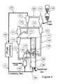
- the embodiment of the apparatus shown in the Figure comprises a first vessel 103 that contains a fluidised bed of gas and entrained solids and a second vessel 105 that contains a fluidised bed of gas and entrained solids.
- the first vessel 103 functions as a heat generator and generates a stream of hot off-gas containing entrained solids, predominantly char, that is transferred to the second vessel 105 via a line 107.
- the purpose of the hot off-gas stream is to provide at least part of the heat required for reactions in the second vessel.
- the second vessel 105 functions as a direct reduction reactor and at least partially reduces iron ore fines in the solid state.
- the second vessel produces two output streams.
- One output stream which is discharged from the second vessel 105 via an outlet 109 in the base of the second vessel 105, comprises a predominantly solids stream of at least partially reduced iron ore fines and entrained solids, typically char.
- the solids stream may be processed by separating the at least partially reduced iron ore fines and the other solids.
- the other solids, predominantly char, may be returned to the first vessel and/or the second vessel as a part of the solids feed for the vessels.
- the at least partially reduced iron ore fines are further processed as required.
- the at least partially reduced iron ore fines may be supplied to a molten bath-based smelting vessel and smelted to molten iron, for example by a process such as the HIsmelt process.
- the other output stream from the second vessel 105 is discharged via an outlet 61 in an upper section of the second vessel 105, comprises hot off-gas and entrained solids.
- the off-gas stream is transferred to a cyclone 113 via a line 111.
- the cyclone 113 separates entrained solids from the off-gas stream.
- the solids flow downwardly from the cyclone 113 via a line 115 and into the first vessel 103 via return leg 155.
- the off-gas stream and any remaining solids flows upwardly from the cyclone 113 into a mixing chamber 117.
- the output stream of off-gas and entrained solids from the mixing chamber 117 flows via a line 125 into a further cyclone 127.
- the off-gas stream from the cyclone 127 mixes with and heats iron ore fines in the mixing chamber 131.
- the iron ore fines are supplied to the mixing chamber 131 via a lock hopper assembly 133.
- the majority of the iron ore feed is carried from mixing chamber 131 to cyclone 121 via line 135.
- Solids separation occurs in cyclone 121 such that a majority of the solids pass via line 123 to mixing chamber 117.
- the solids pass to cyclone 127 via line 125.
- From cyclone 127 the majority of solids pass to the second vessel 105 via line 129.
- the off-gas from the cyclone 121 is transferred via a line 137 to an off-gas processing unit 139 and is treated in the unit as described hereinafter. Specifically, the off-gas is treated by a series of steps of including (a) removing further solids from the off-gas, (b) cooling the off-gas, (c) H 2 O removal, (d) CO 2 removal, (e) compression, and (f) reheating.
- the treated off-gas from the off-gas processing unit 139 becomes a fluidising gas for the vessels 103 and 105. It is transferred to the vessels via a transfer line 141. The fluidising gas is injected into the base of each vessel 103 and 105.
- Medium-high volatile coal having a particle size of minus 6 mm is supplied into a lower section of the first vessel 103 via a lance 143 that extends through a side wall of the first vessel 103.
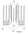
- oxygen is supplied into the first vessel 103 via a lance 145 that has the same basic construction as the lance 45 in Figures 1 , 2 and 3 and directs oxygen downwardly in a central region of the first vessel 103.
- preheated iron ore fines are supplied into the second vessel 105 via the line 129 and the hot off-gas stream containing entrained solids from the first vessel 103 is supplied into the second vessel via the line 107.
- oxygen is supplied into the second vessel 105 via a lance 149 that has the same basic construction as the lance 9 in Figures 1 and 2 that directs the oxygen downwardly in a central region of the second vessel 105.
- the upward stream of fluidising gas and entrained solids in the central region of the first vessel 103 is countercurrent to the downward flow of oxygen gas.
- the coal is devolatilised to char and coal volatiles which then decompose to gaseous products such as H 2 . At least part of the char and the decomposed coal volatiles react with oxygen and form CO and other reaction products. These reactions generate substantial heat and, as is described above, the heat is transferred into the second vessel 105 by the hot output off-gas stream containing entrained solids that flows into the second vessel via the line 107.
- Oxidation of solids and gasses such as partially reduced iron ore particles, char, H 2 and CO, in an upper section of the second vessel 105 which generates heat and promotes controlled agglomeration of smaller partially reduced ore particles with other particles within the fluidised bed.
- the applicant does not have a totally clear understanding at this stage of the mechanism or mechanisms that enable controlled agglomeration of metalliferous material described in the last dot point above to be achieved. Nevertheless, without wishing to be bound by the following comments, in the research project the applicant observed that the agglomerates that formed comprise smaller particles, particularly fines that adhere to each other and to larger particles.
- the applicant speculates that the conditions in the carbon-rich zone, are such that (a) micron sized partially and completely reduced, i.e. metallised, iron ore particles react with oxygen and generate heat and the resultant oxidised particles become sticky (b) fine coal particles react with oxygen and oxidise and the resultant ash becomes sticky ; and (c) fine iron ore particles become sticky as a consequence of being heated.
- these smaller sticky particles adhere to larger particles that have a higher heat sink capacity, with the overall beneficial result that there is a reduction in the proportion of smaller particles in the vessel that can adhere to apparatus surfaces and be carried out from the vessel in an off-gas stream.
- the present invention was made during the course of an on-going research project carried out by the applicant to develop CIRCOFER technology for the direct reduction of iron ore.
- the research project included a series of pilot plant runs on 350mm diameter and 700mm diameter pilot plant set-ups of the applicant.
- the pilot plant comprises an apparatus of the type shown in Figure 1 and 2 .
- the pilot plant was operated as a circulating fluidised bed at atmospheric pressure.
- the vessel has a height of 10.7 m.
- An upper section of the vessel has a height of approximately 8.9 m and an internal diameter of 700 mm.
- a lower section of the vessel has a height of approximately 1.8m and an internal diameter of 500 mm. This height of 1.8 m includes the height of a fluidising grate and a transition section between the 500 mm diameter and the 700 mm diameter sections.
- the vessel is refractory lined.
- Off-gas from the vessel was processed to remove entrained solids by passing the off-gas successively through 3 cyclones connected in series.
- the first cyclone (cyclone 1) received off-gas directly from the vessel. Solids separated in the cyclone were returned to the vessel via a seal pot that provided for pressure sealing.
- the second cyclone (cyclone 2) received off-gas from cyclone 1. Solids separated in the cyclone were returned to the vessel via a direct return of solids (i.e. no seal pot).
- the third cyclone (cyclone 3) received off-gas from the second 2. Solids separated by cyclone 3 were not returned to the vessel.
- the off-gas was further treated by a radial flow scrubber, which further removed solids from the off-gas. These solids were concentrated by a thickener and then passed through a drum filter to produce thickener sludge.
- Off-gas leaving the radial flow scrubber was then treated by a tube cooler that operated to dewater the off-gas by cooling it to within the range 10-30°C. Following treatment by the tube cooler, the off-gas was combusted.
- the fluidised bed was fluidised by air during the initial stages of testing and was later fluidised by a mixture of nitrogen and hydrogen gas.
- process off-gas e.g. CO 2 removal and compression
- hydrogen gas was used to simulate the effect of using processed off-gas as fluidising gas.
- the position of the oxygen lance in the vessel is important because of the desirability of transferring the heat of oxidation back into the bed while minimising the level of iron reoxidation.
- the 4-m position is about right for the conditions tested.
- the primary objective was to achieve stable operation for a significant amount of time with high phosphorus Brockman ore (-3mm) and Blair Athol coal.
- the plan was to operate with low iron ore feed (up to 20% in product discharge) for two days with the oxygen lance in a low position (1.9-m above the distributor plate (not shown in the Figure) of the vessel.
- the aim was then to operate for three days with high ore feed (up to 70% in the product) with the oxygen lance in an upper position (3.8-m above the distributor plate).
- the campaign started on 9 December 2003 at 0600 hrs with a gradual heat up of the 700-mm vessel (hereinafter also referred to as a "CFB") using alumina as the bed material.
- alumina as the bed material.
- coal and oxygen were introduced into the vessel at 1550 hrs.
- the oxygen rate was increased up to 105 Nm 3 /hr while the coal rate was in the range 300-450 kg/hr.
- Iron ore ( ⁇ 3-mm) was introduced into the feed system at 2200 on 10/12/03 at a rate of 10 kg-hr. Hydrogen was also introduced into the fluidising gas at a rate of 20 Nm 3 /hr to simulate use of processed off-gas as fluidising gas. The operation was smooth with the bed ⁇ P being maintained at about 100-120 mbar and the temperature profile having a range of only 10°C between the bottom and the top of the bed.
- the product appeared fine without any signs of accretions or agglomerates. However, on screening the product (at 2mm) some larger scale type material was found but this was only a very small proportion of the overall product. The scale appeared to be made up of ash/char and probably formed on the walls of the vessel or distributor plate in the vessel.
- the iron ore feed rate was increased up to 20 kg/hr at 0600 on 11/12/03 until 1200 11/12/03 and the hydrogen gas rate was also increased up to 40 Nm 3 /hr.
- the operation continued to be smooth without any disruptions.
- the vessel bed pressure was being maintained at about 80-100 mbar and the temperature profile had a range of only 10°C between the bottom and the top of the bed.
- the iron ore feed rate was increased up to 40 kg/hr at 1200 on 11/12/03 and operated with this rate until 0600 12/12/03, while the hydrogen gas rate was maintained at 40 Nm 3 /hr and the coal rate was around 360-420 kg/hr.
- the operation continued to be smooth without any disruptions and the iron product discharge was highly metallised. Dust make was also low with less than 10% of the total discharge coming from the final cyclone (i.e. cyclone 3).
- the vessel bed ⁇ P was being maintained at about 90-135 mbar and the temperature profile had a range of less than 10°C between the bottom and the top of the bed.
- the high metallisation achieved indicates that the oxygen lance (even at its 1.9-m position) did not penetrate too far to the bottom of the bed and that there was good segregation within the bed.
- the lower part of the bed is iron rich.
- the higher part of the bed is carbon rich and this is interacting with the oxygen lance to generate heat and this heat is then transferred back into the bed by the recirculation of the solids to the lower parts of the bed.
- the low CO/CO 2 ratio in the off-gas indicates achievement of high post combustion, with the energy levels being transferred back into the bed, while maintaining high metallisation levels in the product discharge.
- the iron levels in the product and the degree of metallisation indicates that the 700-mm vessel can be operated in gasification mode with up to 20-25% metallic iron content without any problems with accretions. This is a significant achievement.
- the lance was taken out of the 700-mm vessel and inspected on 12/12/03.
- the lance was repositioned in the vessel at a higher position i.e. 3.8-m above the distributor plate.
- the vessel was restarted with coal and oxygen and then once stabilised iron ore and hydrogen. Operation with Iron Ore (110-200 kg/hr), Coal and Oxygen (lance 4-m height) 0600 -1200: Iron Ore at 110 kg/hr
- the iron ore feed rate was increased stepwise up to 110 kg/hr at 0625 and operated with this rate until 1200 while the hydrogen gas rate was also increased stepwise up to 110 Nm 3 /hr over a 2 hr period.
- the coal rate was around 360-400 kg/hr.
- the operation continued to be smooth without any disruptions and the iron product discharge from the vessel was up to 78% metallised. Dust make was also low with ⁇ 10% of the total discharge coming from the final cyclone (i.e. cyclone 3).
- the vessel bed ⁇ P was being maintained at about 90-135 mbar and the temperature profile had a range of less than 5°C between the bottom and the top of the bed.
- the operation rate was approximately 120 kg/h iron ore feed. This included a period of disturbance where there was no feed. The final period operated at approximately 230 kg/h iron ore feed.
- the lance was taken out of the 700-mm vessel and inspected on 16/12/03. In summary, the lance was fairly clean.
- the water cooled pipe had a thin coating of material while the nozzle tip was relatively clean. The nature of the build up (flaky and thin) suggested that this would not lead to any operational problems.
Landscapes
- Engineering & Computer Science (AREA)
- Chemical & Material Sciences (AREA)
- Organic Chemistry (AREA)
- Manufacturing & Machinery (AREA)
- Materials Engineering (AREA)
- Metallurgy (AREA)
- Dispersion Chemistry (AREA)
- Mechanical Engineering (AREA)
- General Engineering & Computer Science (AREA)
- Manufacture And Refinement Of Metals (AREA)
- Devices And Processes Conducted In The Presence Of Fluids And Solid Particles (AREA)
- Crucibles And Fluidized-Bed Furnaces (AREA)
- Manufacture Of Iron (AREA)
- Waste-Gas Treatment And Other Accessory Devices For Furnaces (AREA)
- Furnace Details (AREA)
Claims (37)
- Vorrichtung zur Reduktion eines metallhaltigen Materials in einer Wirbelschicht, die einen Behälter zur Aufnahme der Wirbelschicht aufweist, ein Mittel für die Zufuhr des metallhaltigen Material eines festen kohlenstoffhaltigen Materials, eines Sauerstoff enthaltenen Gases und eines Fluidisierungsgases in den Behälter zur Ausbildung der Wirbelschicht in dem Behälter, wobei die Mittel für die Zufuhr des sauerstoffhaltigen Gases wenigstens eine Injektionslanze für das sauerstoffhaltige Gas umfassen, die eine Lanzenspitze mit einem Auslass aufweist, der zum Einblasen des sauerstoffhaltigen Gases in den Behälter in einer stromabwärts gerichteten Strömung innerhalb eines Bereichs von plus oder minus 40 Grad zur Vertikalen positioniert ist, dadurch gekennzeichnet, dass die Lanze zum Einblasen des sauerstoffhaltigen Gases ein Zentralrohr für das sauerstoffhaltige Gas und einen Durchgang aufweist, der außerhalb des Zentralrohres angeordnet ist, um Abschirmgas einzublasen.
- Vorrichtung nach Anspruch 1, dadurch gekennzeichnet, dass die Lanzenspitze so positioniert ist, dass das sauerstoffhaltige Gas in den Behälter in einer stromabwärts gerichteten Strömung innerhalb eines Bereichs von plus oder minus 15 Grad zur Vertikalen eingeblasen wird.
- Vorrichtung nach Anspruch 1 oder 2, dadurch gekennzeichnet, dass die Lanzenspitze nach unten gerichtet ist.
- Vorrichtung nach einem der vorherigen Ansprüche, dadurch gekennzeichnet, dass die Injektionslanze für das sauerstoffhaltige Gas wassergekühlt ist.
- Vorrichtung nach Anspruch 4, dadurch gekennzeichnet, dass wenigstens die Lanzenspitze eine äußere wassergekühlte Hülle aufweist.
- Vorrichtung nach Anspruch 1, dadurch gekennzeichnet, dass der Durchgang zum Einblasen des Abschirmgases im Querschnitt ein Ring ist.
- Vorrichtung nach Anspruch 6, dadurch gekennzeichnet, dass der Ring im Querschnitt zwischen dem Zentralrohr und der äußeren wassergekühlten Hülle angeordnet ist.
- Vorrichtung nach einem der vorhergehenden Ansprüche, dadurch gekennzeichnet, dass ein unteres Ende des Zentralrohres relativ zu einem unteren Ende der äußeren wassergekühlten Hülle zurückgesetzt ist.
- Vorrichtung nach einem der Ansprüche 5 bis 7, dadurch gekennzeichnet, dass das Zentralrohr eine Abschrägung aufweist, die sich von einer inneren Fläche zu einer äußeren Fläche des Rohres erstreckt.
- Vorrichtung nach einem der vorhergehenden Ansprüche, dadurch gekennzeichnet, dass die Lanze so positioniert ist, dass die Lanzenspitze in einem zentralen Bereich des Behälters mit Abstand zu der Seitenwand des Behälters liegt.
- Vorrichtung nach einem der vorhergehenden Ansprüche, dadurch gekennzeichnet, dass sich die Lanze nach unten durch eine obere Wand des Behälters erstreckt.
- Vorrichtung nach Anspruch 11, dadurch gekennzeichnet, dass sich die Lanze vertikal nach unten durch die obere Wand des Behälters erstreckt.
- Vorrichtung nach einem der Ansprüche 1 bis 10, dadurch gekennzeichnet, dass sich die Lanze durch die Seitenwand des Behälters und dann nach unten erstreckt.
- Vorrichtung nach einem der Ansprüche 1 bis 10, dadurch gekennzeichnet, dass sich die Lanze horizontal durch die Seitenwand des Behälters und dann nach unten erstreckt.
- Verfahren zur Reduktion eines metallhaltigen Materials in einer Wirbelschicht in einem Behälter, welches umfasst das Zuführen eines metallhaltigen Materials, eines festen kohlenstoffhaltigen Materials, eines sauerstoffhaltigen Gases und eines Fluidisierungsgases in die Wirbelschicht und das Aufrechterhalten der Wirbelschicht in dem Behälter, das wenigstens teilweise Reduzieren des metallhaltigen Materials in den Behälter und das Abführen eines Produktstroms, welcher das wenigstens teilweise reduzierte metallhaltige Material aus dem Behälter umfasst, und eines separaten Abgasstroms, und das Einblasen des sauerstoffhaltigen Gases in den Behälter mit einer nach unten gerichteten Strömung in einem Bereich von plus oder minus 40 Grad zur Vertikalen über eine oder mehr als eine Lanze, dadurch gekennzeichnet, dass das Verfahren das Einblasen von Stickstoff und/oder Dampf und/oder anderem geeignetem Abschirmgas und das Abschirmen eines unteren Endes der Lanzenspritze umfasst.
- Verfahren nach Anspruch 15, dadurch gekennzeichnet, dass das Verfahren das Einblasen des sauerstoffhaltigen Gases in einen zentralen Bereich in dem Behälter über eine Lanze aufweist, welche eine nach unten gerichtete Lanzenspitze hat, die an der Seitenwand des Behälters nach innen positioniert ist.
- Verfahren nach Anspruch 16, dadurch gekennzeichnet, dass das Verfahren die Wasserkühlung der Lanzenspitze umfasst.
- Verfahren nach einem der Ansprüche 15 bis 17, dadurch gekennzeichnet, dass das Verfahren das Einblasen des sauerstoffhaltigen Gases mit ausreichender Geschwindigkeit zur Ausbildung einer im Wesentlichen feststofffreien Zone in dem Bereich der Lanzenspitze umfasst.
- Verfahren nach Anspruch 18, gekennzeichnet durch das Einblasen des sauerstoffhaltigen Gases mit einer Geschwindigkeit im Bereich von 50 bis 300 m/s.
- Verfahren nach Anspruch 15, gekennzeichnet durch das Einblasen des Abschirmgases in den Behälter mit einer Geschwindigkeit, die bei wenigstens 60% der Geschwindigkeit des sauerstoffhaltigen Gases liegt.
- Verfahren nach einem der Ansprüche 15 bis 20, gekennzeichnet durch das Zuführen des metallhaltigen Materials, des festen kohlenstoffhaltigen Materials, des sauerstoffhaltigen Gases und des Fluidisierungsgases in die Wirbelschicht und das Aufrechterhalten der Wirbelschicht mit (a) einer abwärts gerichteten Strömung des sauerstoffhaltigen Gases (b) einer aufwärts gerichteten Strömung von Feststoffen und Fluidisierungsgas im Gegenstrom zu der abwärts gerichteten Strömung des sauerstoffhaltigen Gases und (c) einer abwärts gerichteten Strömung von Feststoffen außerhalb der Aufwärtsströmung von Feststoffen und Fluidisiergas.
- Verfahren nach einem der Ansprüche 15 bis 21, gekennzeichnet durch die Reduktion von Eisenerzfeinteilen mit einer Größe von kleiner als 6 mm.
- Verfahren nach einem der Ansprüche 15 bis 22, dadurch gekennzeichnet, dass die Feinteile eine durchschnittliche Partikelgröße im Bereich von 0,1 bis 0,8 mm aufweisen.
- Verfahren nach einem der Ansprüche 15 bis 23, gekennzeichnet durch das Abführen des Produktstroms, welcher wenigstens teilweise reduziertes metallhaltiges Material umfasst, von dem unteren Abschnitt des Behälters.
- Verfahren nach einem der Ansprüche 15 bis 24, wobei der Produktstrom außerdem andere Feststoffe aufweist, dadurch gekennzeichnet, dass das Verfahren das Abtrennen wenigstens eines Teils der anderen Feststoffe von dem Produktstrom und das Rückführen der abgetrennten Feststoffe zu dem Behälter umfasst.
- Verfahren nach einem der Ansprüche 15 bis 25, gekennzeichnet durch das Abtrennen von mitgeführten Feststoffen aus dem Abgasstrom.
- Verfahren nach einem der Ansprüche 15 bis 26, gekennzeichnet durch das Aufrechterhalten einer zirkulierenden Wirbelschicht und das Rückführen von mitgeführten Feststoffen zu einem unteren Bereich des Behälters.
- Verfahren nach einem der Ansprüche 15 bis 27, gekennzeichnet durch das Vorwärmen von metallhaltigem Zufuhrmaterial mit dem Abgas aus dem Behälter.
- Verfahren nach einem der Ansprüche 15 bis 28, gekennzeichnet durch die Behandlung des Abgases nach der Vorwärmstufe und das Rückführen wenigstens eines Teils des behandeltem Abgases zu dem Behälter als Fluidisierungsgas.
- Verfahren nach einem der Ansprüche 15 bis 29, dadurch gekennzeichnet, dass die Abgasbehandlung die (a) Feststoffentfernung, (b) Kühlung, (c) H2O Entfernung (d) CO2 Entfernung, (e) Kompression und/oder (f) Wiedererwärmung umfasst.
- Verfahren nach einem der Ansprüche 15 bis 30, dadurch gekennzeichnet, dass die Abgasbehandlung die Rückführung von Feststoffen zu dem Behälter umfasst.
- Verfahren nach einem der Ansprüche 15 bis 31, dadurch gekennzeichnet, dass es als ein einstufiger Prozess in einem einzigen Behälter durchgeführt wird.
- Verfahren nach einem der Ansprüche 15 bis 31, dadurch gekennzeichnet, dass es als ein mehrstufiger Prozess in zwei oder mehr Behältern durchgeführt wird.
- Verfahren nach Anspruch 33, dadurch gekennzeichnet, dass der mehrstufige Prozess eine erste Stufe umfasst, in welcher Wärme durch Reaktionen zwischen festem kohlenstoffhaltigen Material und sauerstoffhaltigem Gas in einer Wirbelschicht in einem ersten Behälter generiert und metallhaltiges Material in einer Wirbelschicht in einem zweiten Behälter reduziert wird, wobei der zweiten Wirbelschicht Wärme teilweise über einen Strom heißen Abgases und mitgeführter Feststoffe aus der ersten Wirbelschicht zugeführt wird.
- Verfahren nach Anspruch 33 oder 34, dadurch gekennzeichnet, dass auch dem zweiten Behälter sauerstoffhaltiges Gas zugeführt wird.
- Verfahren nach Anspruch 35, dadurch gekennzeichnet, dass die Zufuhr von sauerstoffhaltigem Gas, das dem zweiten Behälter zugeführt wird, unter derart kontrollierten Bedingungen durchgeführt wird, dass eine gewünschte Agglomeration kleiner reduzierter Erzpartikel mit anderen Partikeln des Zufuhrmaterials zur Bildung größerer reduzierter Erzpartikel erfolgt.
- Verfahren nach einem der Ansprüche 15 bis 36, dadurch gekennzeichnet, dass das sauerstoffhaltige Gas wenigstens 90 Vol.-% Sauerstoff aufweist.
Priority Applications (1)
| Application Number | Priority Date | Filing Date | Title |
|---|---|---|---|
| PL05741974T PL1766099T3 (pl) | 2004-05-31 | 2005-05-20 | Urządzenie i proces służące do bezpośredniej redukcji |
Applications Claiming Priority (2)
| Application Number | Priority Date | Filing Date | Title |
|---|---|---|---|
| AU2004902901A AU2004902901A0 (en) | 2004-05-31 | A direct reduction process | |
| PCT/EP2005/005471 WO2005116275A2 (en) | 2004-05-31 | 2005-05-20 | A direct reduction apparatus and process |
Publications (2)
| Publication Number | Publication Date |
|---|---|
| EP1766099A2 EP1766099A2 (de) | 2007-03-28 |
| EP1766099B1 true EP1766099B1 (de) | 2013-11-06 |
Family
ID=35448177
Family Applications (1)
| Application Number | Title | Priority Date | Filing Date |
|---|---|---|---|
| EP05741974.9A Expired - Lifetime EP1766099B1 (de) | 2004-05-31 | 2005-05-20 | Direktreduktionsverfahren |
Country Status (14)
| Country | Link |
|---|---|
| US (2) | US7824603B2 (de) |
| EP (1) | EP1766099B1 (de) |
| JP (1) | JP4785839B2 (de) |
| CN (1) | CN100554438C (de) |
| BR (1) | BRPI0511680B1 (de) |
| CA (1) | CA2566320C (de) |
| EA (1) | EA010204B1 (de) |
| ES (1) | ES2441728T3 (de) |
| NZ (1) | NZ551517A (de) |
| PL (1) | PL1766099T3 (de) |
| TW (1) | TWI379910B (de) |
| UA (1) | UA86234C2 (de) |
| WO (1) | WO2005116275A2 (de) |
| ZA (1) | ZA200609569B (de) |
Families Citing this family (7)
| Publication number | Priority date | Publication date | Assignee | Title |
|---|---|---|---|---|
| DE102007006981B4 (de) * | 2007-02-07 | 2009-01-29 | Technische Universität Bergakademie Freiberg | Verfahren, Vergasungsreaktor und Anlage zur Flugstromvergasung fester Brennstoffe unter Druck |
| AT507607B1 (de) * | 2008-11-28 | 2011-02-15 | Siemens Vai Metals Tech Gmbh | Düse zum eindüsen von sauerstoffhaltigem gas in ein roheisenaggregat mit injektoreinsatzröhre |
| AT508522B1 (de) | 2009-07-31 | 2011-04-15 | Siemens Vai Metals Tech Gmbh | Reformergasbasiertes reduktionsverfahren mit vermindertem nox-ausstoss |
| DE102010022773B4 (de) | 2010-06-04 | 2012-10-04 | Outotec Oyj | Verfahren und Anlage zur Erzeugung von Roheisen |
| CA2816347C (en) * | 2010-11-03 | 2020-05-19 | Technological Resources Pty. Limited | Production of iron |
| EP4158074A4 (de) * | 2020-05-29 | 2024-05-01 | Technological Resources Pty Limited | Direkt reduziertes eisen aus biomasse |
| CN112251599B (zh) * | 2020-10-16 | 2022-08-05 | 中科南京绿色制造产业创新研究院 | 一种氧化锰矿流态化还原装置及方法 |
Family Cites Families (14)
| Publication number | Priority date | Publication date | Assignee | Title |
|---|---|---|---|---|
| US2921848A (en) * | 1957-11-21 | 1960-01-19 | United States Steel Corp | Fluidized-bed reduction of ore |
| BE759490A (fr) * | 1969-11-28 | 1971-04-30 | Nippon Kokan Kk | Procede pour introduire par soufflage un gaz dans un lit fluidise |
| US3928021A (en) * | 1970-12-28 | 1975-12-23 | Nippon Kokan Kk | Process of reducing iron ores |
| SE419129B (sv) * | 1979-05-29 | 1981-07-13 | Stora Kopparbergs Bergslags Ab | Anordning for reduktion av finfordelat jernoxidhaltigt material i en cirkulerande flytbedd |
| SE429898B (sv) * | 1980-01-16 | 1983-10-03 | Stora Kopparbergs Bergslags Ab | Sett att forhindra pakladdning vid reduktion i flytbedd av finfordelat metalloxidhaltigt material |
| JPS56108090A (en) * | 1980-01-31 | 1981-08-27 | Kawasaki Steel Co | Gas blowinggin nozzle for heat medium particle circulation fluid layer |
| JPS6169910A (ja) * | 1984-09-12 | 1986-04-10 | Kobe Steel Ltd | 鉄鉱石の流動層還元方法 |
| DE3626027A1 (de) * | 1986-08-01 | 1988-02-11 | Metallgesellschaft Ag | Verfahren zur reduktion feinkoerniger, eisenhaltiger materialien mit festen kohlenstoffhaltigen reduktionsmitteln |
| CN2195077Y (zh) * | 1994-06-17 | 1995-04-19 | 冶金工业部鞍山热能研究院 | 炼钢熔池喷吹热物料用的氧燃枪 |
| KR100270113B1 (ko) * | 1996-10-08 | 2000-10-16 | 이구택 | 극저탄소강의 용강 제조장치 |
| JPH11131118A (ja) * | 1997-10-31 | 1999-05-18 | Nkk Corp | 予備還元炉 |
| US20030090044A1 (en) * | 2001-11-14 | 2003-05-15 | Xueping Li | Method and apparatus for melting metal in a shaft furnace |
| GB0128878D0 (en) * | 2001-12-03 | 2002-01-23 | Boc Group Plc | Metallurgical lance and apparatus |
| CN1754003B (zh) * | 2002-12-23 | 2012-05-30 | Posco公司 | 用于改善流化床型还原设备操作的制造铁水的设备及其使用方法 |
-
2005
- 2005-05-20 US US11/569,734 patent/US7824603B2/en not_active Expired - Fee Related
- 2005-05-20 UA UAA200612407A patent/UA86234C2/uk unknown
- 2005-05-20 CA CA2566320A patent/CA2566320C/en not_active Expired - Fee Related
- 2005-05-20 PL PL05741974T patent/PL1766099T3/pl unknown
- 2005-05-20 NZ NZ551517A patent/NZ551517A/en not_active IP Right Cessation
- 2005-05-20 ES ES05741974.9T patent/ES2441728T3/es not_active Expired - Lifetime
- 2005-05-20 CN CNB2005800177392A patent/CN100554438C/zh not_active Expired - Fee Related
- 2005-05-20 EP EP05741974.9A patent/EP1766099B1/de not_active Expired - Lifetime
- 2005-05-20 BR BRPI0511680A patent/BRPI0511680B1/pt not_active IP Right Cessation
- 2005-05-20 EA EA200601978A patent/EA010204B1/ru not_active IP Right Cessation
- 2005-05-20 WO PCT/EP2005/005471 patent/WO2005116275A2/en not_active Ceased
- 2005-05-20 JP JP2007513760A patent/JP4785839B2/ja not_active Expired - Fee Related
- 2005-05-30 TW TW094117636A patent/TWI379910B/zh not_active IP Right Cessation
-
2006
- 2006-11-17 ZA ZA200609569A patent/ZA200609569B/en unknown
-
2010
- 2010-07-08 US US12/832,847 patent/US7947107B2/en not_active Expired - Fee Related
Also Published As
| Publication number | Publication date |
|---|---|
| WO2005116275A3 (en) | 2006-03-09 |
| ZA200609569B (en) | 2008-05-28 |
| EA200601978A1 (ru) | 2007-06-29 |
| PL1766099T3 (pl) | 2014-04-30 |
| CA2566320C (en) | 2012-11-27 |
| CN1961083A (zh) | 2007-05-09 |
| JP4785839B2 (ja) | 2011-10-05 |
| WO2005116275A2 (en) | 2005-12-08 |
| TWI379910B (en) | 2012-12-21 |
| UA86234C2 (uk) | 2009-04-10 |
| US20080210055A1 (en) | 2008-09-04 |
| CA2566320A1 (en) | 2005-12-08 |
| BRPI0511680B1 (pt) | 2016-03-29 |
| US20100269636A1 (en) | 2010-10-28 |
| ES2441728T3 (es) | 2014-02-06 |
| US7824603B2 (en) | 2010-11-02 |
| JP2008501098A (ja) | 2008-01-17 |
| BRPI0511680A (pt) | 2008-01-08 |
| NZ551517A (en) | 2009-07-31 |
| EA010204B1 (ru) | 2008-06-30 |
| EP1766099A2 (de) | 2007-03-28 |
| TW200611979A (en) | 2006-04-16 |
| US7947107B2 (en) | 2011-05-24 |
| CN100554438C (zh) | 2009-10-28 |
Similar Documents
| Publication | Publication Date | Title |
|---|---|---|
| US7947107B2 (en) | Direct reduction apparatus and process | |
| EP1753883B1 (de) | Verfahren und vorrichtung für direktreduktion | |
| EP1756322B1 (de) | Direktreduktionsverfahren | |
| EP1756324B1 (de) | Wirbelschichtverfahren zur direktreduktion in einem einzigen wirbelbett | |
| AU2005248041B2 (en) | A direct reduction apparatus and process | |
| AU2005248040B2 (en) | A direct reduction process | |
| AU2005248042B2 (en) | Direct reduction process using a single fluidised bed |
Legal Events
| Date | Code | Title | Description |
|---|---|---|---|
| PUAI | Public reference made under article 153(3) epc to a published international application that has entered the european phase |
Free format text: ORIGINAL CODE: 0009012 |
|
| 17P | Request for examination filed |
Effective date: 20060902 |
|
| AK | Designated contracting states |
Kind code of ref document: A2 Designated state(s): AT BE BG CH CY CZ DE DK EE ES FI FR GB GR HU IE IS IT LI LT LU MC NL PL PT RO SE SI SK TR |
|
| AX | Request for extension of the european patent |
Extension state: AL BA HR LV MK YU |
|
| RAP1 | Party data changed (applicant data changed or rights of an application transferred) |
Owner name: OUTOTEC OYJ |
|
| 17Q | First examination report despatched |
Effective date: 20071130 |
|
| RIC1 | Information provided on ipc code assigned before grant |
Ipc: F27B 15/10 20060101ALI20130325BHEP Ipc: C21B 13/14 20060101ALI20130325BHEP Ipc: C21B 13/00 20060101AFI20130325BHEP |
|
| GRAP | Despatch of communication of intention to grant a patent |
Free format text: ORIGINAL CODE: EPIDOSNIGR1 |
|
| INTG | Intention to grant announced |
Effective date: 20130527 |
|
| GRAS | Grant fee paid |
Free format text: ORIGINAL CODE: EPIDOSNIGR3 |
|
| GRAA | (expected) grant |
Free format text: ORIGINAL CODE: 0009210 |
|
| RAP1 | Party data changed (applicant data changed or rights of an application transferred) |
Owner name: OUTOTEC OYJ |
|
| AK | Designated contracting states |
Kind code of ref document: B1 Designated state(s): AT BE BG CH CY CZ DE DK EE ES FI FR GB GR HU IE IS IT LI LT LU MC NL PL PT RO SE SI SK TR |
|
| AX | Request for extension of the european patent |
Extension state: AL BA HR LV MK YU |
|
| REG | Reference to a national code |
Ref country code: GB Ref legal event code: FG4D |
|
| REG | Reference to a national code |
Ref country code: CH Ref legal event code: EP |
|
| REG | Reference to a national code |
Ref country code: AT Ref legal event code: REF Ref document number: 639551 Country of ref document: AT Kind code of ref document: T Effective date: 20131215 |
|
| REG | Reference to a national code |
Ref country code: IE Ref legal event code: FG4D |
|
| REG | Reference to a national code |
Ref country code: DE Ref legal event code: R096 Ref document number: 602005041765 Country of ref document: DE Effective date: 20140102 |
|
| REG | Reference to a national code |
Ref country code: ES Ref legal event code: FG2A Ref document number: 2441728 Country of ref document: ES Kind code of ref document: T3 Effective date: 20140206 |
|
| REG | Reference to a national code |
Ref country code: SE Ref legal event code: TRGR |
|
| REG | Reference to a national code |
Ref country code: NL Ref legal event code: VDEP Effective date: 20131106 |
|
| REG | Reference to a national code |
Ref country code: LT Ref legal event code: MG4D |
|
| PG25 | Lapsed in a contracting state [announced via postgrant information from national office to epo] |
Ref country code: LT Free format text: LAPSE BECAUSE OF FAILURE TO SUBMIT A TRANSLATION OF THE DESCRIPTION OR TO PAY THE FEE WITHIN THE PRESCRIBED TIME-LIMIT Effective date: 20131106 Ref country code: NL Free format text: LAPSE BECAUSE OF FAILURE TO SUBMIT A TRANSLATION OF THE DESCRIPTION OR TO PAY THE FEE WITHIN THE PRESCRIBED TIME-LIMIT Effective date: 20131106 Ref country code: IS Free format text: LAPSE BECAUSE OF FAILURE TO SUBMIT A TRANSLATION OF THE DESCRIPTION OR TO PAY THE FEE WITHIN THE PRESCRIBED TIME-LIMIT Effective date: 20140306 |
|
| REG | Reference to a national code |
Ref country code: PL Ref legal event code: T3 |
|
| PG25 | Lapsed in a contracting state [announced via postgrant information from national office to epo] |
Ref country code: PT Free format text: LAPSE BECAUSE OF FAILURE TO SUBMIT A TRANSLATION OF THE DESCRIPTION OR TO PAY THE FEE WITHIN THE PRESCRIBED TIME-LIMIT Effective date: 20140306 |
|
| PG25 | Lapsed in a contracting state [announced via postgrant information from national office to epo] |
Ref country code: EE Free format text: LAPSE BECAUSE OF FAILURE TO SUBMIT A TRANSLATION OF THE DESCRIPTION OR TO PAY THE FEE WITHIN THE PRESCRIBED TIME-LIMIT Effective date: 20131106 |
|
| REG | Reference to a national code |
Ref country code: DE Ref legal event code: R097 Ref document number: 602005041765 Country of ref document: DE |
|
| PG25 | Lapsed in a contracting state [announced via postgrant information from national office to epo] |
Ref country code: SK Free format text: LAPSE BECAUSE OF FAILURE TO SUBMIT A TRANSLATION OF THE DESCRIPTION OR TO PAY THE FEE WITHIN THE PRESCRIBED TIME-LIMIT Effective date: 20131106 Ref country code: CZ Free format text: LAPSE BECAUSE OF FAILURE TO SUBMIT A TRANSLATION OF THE DESCRIPTION OR TO PAY THE FEE WITHIN THE PRESCRIBED TIME-LIMIT Effective date: 20131106 Ref country code: RO Free format text: LAPSE BECAUSE OF FAILURE TO SUBMIT A TRANSLATION OF THE DESCRIPTION OR TO PAY THE FEE WITHIN THE PRESCRIBED TIME-LIMIT Effective date: 20131106 |
|
| PLBE | No opposition filed within time limit |
Free format text: ORIGINAL CODE: 0009261 |
|
| STAA | Information on the status of an ep patent application or granted ep patent |
Free format text: STATUS: NO OPPOSITION FILED WITHIN TIME LIMIT |
|
| PG25 | Lapsed in a contracting state [announced via postgrant information from national office to epo] |
Ref country code: DK Free format text: LAPSE BECAUSE OF FAILURE TO SUBMIT A TRANSLATION OF THE DESCRIPTION OR TO PAY THE FEE WITHIN THE PRESCRIBED TIME-LIMIT Effective date: 20131106 |
|
| 26N | No opposition filed |
Effective date: 20140807 |
|
| REG | Reference to a national code |
Ref country code: DE Ref legal event code: R097 Ref document number: 602005041765 Country of ref document: DE Effective date: 20140807 |
|
| PG25 | Lapsed in a contracting state [announced via postgrant information from national office to epo] |
Ref country code: LU Free format text: LAPSE BECAUSE OF FAILURE TO SUBMIT A TRANSLATION OF THE DESCRIPTION OR TO PAY THE FEE WITHIN THE PRESCRIBED TIME-LIMIT Effective date: 20140520 |
|
| REG | Reference to a national code |
Ref country code: CH Ref legal event code: PL |
|
| PG25 | Lapsed in a contracting state [announced via postgrant information from national office to epo] |
Ref country code: LI Free format text: LAPSE BECAUSE OF NON-PAYMENT OF DUE FEES Effective date: 20140531 Ref country code: CH Free format text: LAPSE BECAUSE OF NON-PAYMENT OF DUE FEES Effective date: 20140531 Ref country code: MC Free format text: LAPSE BECAUSE OF FAILURE TO SUBMIT A TRANSLATION OF THE DESCRIPTION OR TO PAY THE FEE WITHIN THE PRESCRIBED TIME-LIMIT Effective date: 20131106 |
|
| REG | Reference to a national code |
Ref country code: IE Ref legal event code: MM4A |
|
| PG25 | Lapsed in a contracting state [announced via postgrant information from national office to epo] |
Ref country code: SI Free format text: LAPSE BECAUSE OF FAILURE TO SUBMIT A TRANSLATION OF THE DESCRIPTION OR TO PAY THE FEE WITHIN THE PRESCRIBED TIME-LIMIT Effective date: 20131106 |
|
| PG25 | Lapsed in a contracting state [announced via postgrant information from national office to epo] |
Ref country code: IE Free format text: LAPSE BECAUSE OF NON-PAYMENT OF DUE FEES Effective date: 20140520 |
|
| REG | Reference to a national code |
Ref country code: FR Ref legal event code: PLFP Year of fee payment: 12 |
|
| PG25 | Lapsed in a contracting state [announced via postgrant information from national office to epo] |
Ref country code: BG Free format text: LAPSE BECAUSE OF FAILURE TO SUBMIT A TRANSLATION OF THE DESCRIPTION OR TO PAY THE FEE WITHIN THE PRESCRIBED TIME-LIMIT Effective date: 20131106 |
|
| PG25 | Lapsed in a contracting state [announced via postgrant information from national office to epo] |
Ref country code: CY Free format text: LAPSE BECAUSE OF FAILURE TO SUBMIT A TRANSLATION OF THE DESCRIPTION OR TO PAY THE FEE WITHIN THE PRESCRIBED TIME-LIMIT Effective date: 20131106 Ref country code: GR Free format text: LAPSE BECAUSE OF FAILURE TO SUBMIT A TRANSLATION OF THE DESCRIPTION OR TO PAY THE FEE WITHIN THE PRESCRIBED TIME-LIMIT Effective date: 20140207 |
|
| PG25 | Lapsed in a contracting state [announced via postgrant information from national office to epo] |
Ref country code: TR Free format text: LAPSE BECAUSE OF FAILURE TO SUBMIT A TRANSLATION OF THE DESCRIPTION OR TO PAY THE FEE WITHIN THE PRESCRIBED TIME-LIMIT Effective date: 20131106 Ref country code: HU Free format text: LAPSE BECAUSE OF FAILURE TO SUBMIT A TRANSLATION OF THE DESCRIPTION OR TO PAY THE FEE WITHIN THE PRESCRIBED TIME-LIMIT; INVALID AB INITIO Effective date: 20050520 |
|
| REG | Reference to a national code |
Ref country code: FR Ref legal event code: PLFP Year of fee payment: 13 |
|
| PGFP | Annual fee paid to national office [announced via postgrant information from national office to epo] |
Ref country code: LU Payment date: 20170608 Year of fee payment: 13 |
|
| REG | Reference to a national code |
Ref country code: FR Ref legal event code: PLFP Year of fee payment: 14 |
|
| PGFP | Annual fee paid to national office [announced via postgrant information from national office to epo] |
Ref country code: FI Payment date: 20180521 Year of fee payment: 14 Ref country code: DE Payment date: 20180522 Year of fee payment: 14 |
|
| PGFP | Annual fee paid to national office [announced via postgrant information from national office to epo] |
Ref country code: BE Payment date: 20180518 Year of fee payment: 14 Ref country code: AT Payment date: 20180522 Year of fee payment: 14 Ref country code: FR Payment date: 20180522 Year of fee payment: 14 Ref country code: IT Payment date: 20180528 Year of fee payment: 14 Ref country code: PL Payment date: 20180419 Year of fee payment: 14 |
|
| PGFP | Annual fee paid to national office [announced via postgrant information from national office to epo] |
Ref country code: SE Payment date: 20180518 Year of fee payment: 14 |
|
| PGFP | Annual fee paid to national office [announced via postgrant information from national office to epo] |
Ref country code: GB Payment date: 20180518 Year of fee payment: 14 |
|
| REG | Reference to a national code |
Ref country code: ES Ref legal event code: FD2A Effective date: 20190913 |
|
| PG25 | Lapsed in a contracting state [announced via postgrant information from national office to epo] |
Ref country code: ES Free format text: LAPSE BECAUSE OF NON-PAYMENT OF DUE FEES Effective date: 20180521 |
|
| REG | Reference to a national code |
Ref country code: DE Ref legal event code: R119 Ref document number: 602005041765 Country of ref document: DE |
|
| REG | Reference to a national code |
Ref country code: AT Ref legal event code: MM01 Ref document number: 639551 Country of ref document: AT Kind code of ref document: T Effective date: 20190520 |
|
| GBPC | Gb: european patent ceased through non-payment of renewal fee |
Effective date: 20190520 |
|
| PG25 | Lapsed in a contracting state [announced via postgrant information from national office to epo] |
Ref country code: SE Free format text: LAPSE BECAUSE OF NON-PAYMENT OF DUE FEES Effective date: 20190521 Ref country code: FI Free format text: LAPSE BECAUSE OF NON-PAYMENT OF DUE FEES Effective date: 20190520 Ref country code: AT Free format text: LAPSE BECAUSE OF NON-PAYMENT OF DUE FEES Effective date: 20190520 |
|
| REG | Reference to a national code |
Ref country code: BE Ref legal event code: MM Effective date: 20190531 |
|
| PG25 | Lapsed in a contracting state [announced via postgrant information from national office to epo] |
Ref country code: DE Free format text: LAPSE BECAUSE OF NON-PAYMENT OF DUE FEES Effective date: 20191203 Ref country code: GB Free format text: LAPSE BECAUSE OF NON-PAYMENT OF DUE FEES Effective date: 20190520 Ref country code: IT Free format text: LAPSE BECAUSE OF NON-PAYMENT OF DUE FEES Effective date: 20190520 |
|
| REG | Reference to a national code |
Ref country code: SE Ref legal event code: EUG |
|
| PG25 | Lapsed in a contracting state [announced via postgrant information from national office to epo] |
Ref country code: BE Free format text: LAPSE BECAUSE OF NON-PAYMENT OF DUE FEES Effective date: 20190531 |
|
| PG25 | Lapsed in a contracting state [announced via postgrant information from national office to epo] |
Ref country code: FR Free format text: LAPSE BECAUSE OF NON-PAYMENT OF DUE FEES Effective date: 20190531 |
|
| PG25 | Lapsed in a contracting state [announced via postgrant information from national office to epo] |
Ref country code: PL Free format text: LAPSE BECAUSE OF NON-PAYMENT OF DUE FEES Effective date: 20190520 |