EP1766206B1 - Kühlmittel-pflege-einheit mit rücklaufsperrventil - Google Patents
Kühlmittel-pflege-einheit mit rücklaufsperrventil Download PDFInfo
- Publication number
- EP1766206B1 EP1766206B1 EP05767862A EP05767862A EP1766206B1 EP 1766206 B1 EP1766206 B1 EP 1766206B1 EP 05767862 A EP05767862 A EP 05767862A EP 05767862 A EP05767862 A EP 05767862A EP 1766206 B1 EP1766206 B1 EP 1766206B1
- Authority
- EP
- European Patent Office
- Prior art keywords
- housing
- coolant
- cover
- stop valve
- filter
- Prior art date
- Legal status (The legal status is an assumption and is not a legal conclusion. Google has not performed a legal analysis and makes no representation as to the accuracy of the status listed.)
- Expired - Lifetime
Links
Images



Classifications
-
- F—MECHANICAL ENGINEERING; LIGHTING; HEATING; WEAPONS; BLASTING
- F01—MACHINES OR ENGINES IN GENERAL; ENGINE PLANTS IN GENERAL; STEAM ENGINES
- F01P—COOLING OF MACHINES OR ENGINES IN GENERAL; COOLING OF INTERNAL-COMBUSTION ENGINES
- F01P11/00—Component parts, details, or accessories not provided for in, or of interest apart from, groups F01P1/00 - F01P9/00
- F01P11/06—Cleaning; Combating corrosion
-
- B—PERFORMING OPERATIONS; TRANSPORTING
- B01—PHYSICAL OR CHEMICAL PROCESSES OR APPARATUS IN GENERAL
- B01D—SEPARATION
- B01D35/00—Filtering devices having features not specifically covered by groups B01D24/00 - B01D33/00, or for applications not specifically covered by groups B01D24/00 - B01D33/00; Auxiliary devices for filtration; Filter housing constructions
- B01D35/14—Safety devices specially adapted for filtration; Devices for indicating clogging
- B01D35/153—Anti-leakage or anti-return valves
-
- F—MECHANICAL ENGINEERING; LIGHTING; HEATING; WEAPONS; BLASTING
- F01—MACHINES OR ENGINES IN GENERAL; ENGINE PLANTS IN GENERAL; STEAM ENGINES
- F01P—COOLING OF MACHINES OR ENGINES IN GENERAL; COOLING OF INTERNAL-COMBUSTION ENGINES
- F01P11/00—Component parts, details, or accessories not provided for in, or of interest apart from, groups F01P1/00 - F01P9/00
- F01P11/06—Cleaning; Combating corrosion
- F01P2011/061—Cleaning or combating corrosion using filters
Definitions
- the invention relates to a coolant care unit according to the preamble of claim 1.
- Such coolant care units are for example from the practice and from the US 5,753,116 known. On the one hand, they offer the possibility of extending the service life by filtering the coolant.
- care units is usually provided to use when changing the filter cartridge with a care product, which is automatically opened when using the filter insert into the housing and introduces care additives in the coolant circuit, for example, so-called “inhibitors” which serve, for example, as frost and corrosion protection can.
- the so-called filter change in such coolant care units ie the change of the filter insert, when the coolant is still a relatively high temperature and the coolant system is under pressure.
- the invention has for its object to improve a generic coolant care unit to the effect that this allows a safe replacement of the filter cartridge and in particular a safe opening of the coolant filter.
- This object is achieved by a coolant care unit having the features of claim 1.
- the invention proposes to shut off the interior of the filter housing from the rest of the coolant circuit so that overpressure prevailing in the coolant circuit can not result in hot coolant leaking out of the filter housing when the cover is removed from the housing.
- the pressure prevailing in the filter housing itself pressure is reduced by the fact that the lid is removed and meanwhile the coolant in the filter housing can relax before the lid is completely removed and the seal composite between the lid and housing is repealed.
- a check valve may be provided so that, driven by the coolant pump, during normal operation on the clean side of the coolant filter, there is a greater pressure than in the rest of the coolant circuit, where the "remaining coolant circuit" the points of the coolant circuit in the present proposal be understood that connect directly to the aforementioned, proposed by the proposed valves. Due to the pressure difference, the check valve opens during normal operation. In a filter change or when the coolant filter is opened for other reasons and the pressure inside the filter is relaxed, there is a lower pressure than in the rest of the coolant circuit, so that the aforementioned check valve blocks in the return.
- a check valve is provided, which is not pressure-actuated, but opens and closes away.
- the movable valve body of this check valve pushed into its open position. If the cover is removed from the housing, while the filter insert is also moved at the same time, which is connected to the lid, for example by a clip connection.
- a movement of the valve body may also be provided solely due to the pressure prevailing in the rest of the coolant circuit, so that when the filter cartridge is removed from the valve body, the check valve will not remain forcibly opened, but will be forced into its closed position following the pressure in the coolant circuit can be.
- the filter element can be configured in a manner known per se as an approximately cylindrical insert with an upper end plate, which has, for example, the locking means for connection to the lid and with a lower end plate, which rests as a pressure plate the valve body or indirectly or directly on the valve body acts and pushes it in its open position when the filter cartridge is in its operating position.
- a plunger may be provided, which adjoins the valve body and extends to the end plate of the filter insert.
- a plunger may be provided, which adjoins the valve body and extends to the end plate of the filter insert.
- the aforesaid end plate may preferably be reinforced in the region which acts on the check valve.
- the end plate can be basically designed to save material, while it is stiffened only in the required area, which acts on the check valve, so that a reliable actuation of the check valve is ensured and deformations of the end plate, as they occur under operating temperatures and Pressing could occur are excluded.
- a total of a coolant care unit This has a cup-shaped housing 2 and a lid 3, which is designed as a screw cap and is screwed to the housing 2. Between cover 3 and housing 2, a circumferential O-ring seal 4 is provided.
- the cover 3 has a displacement body 5, which prevents the interior of the housing 2 can be completely filled with coolant. Upon removal of the cover 3 from the housing 2, therefore, the liquid level inside the housing is lowered automatically, so that is ensured even at inclinations of the housing 2 in a normal operation during operation, that no coolant can flow over the top of the housing 2, but reliable remains within the housing 2.
- a filter insert 6 is connected to the cover 3, specifically via a latching connection 7, which is provided on an upper end disk 8 of the filter element 6, which is generally cylindrical in shape.
- the filter insert 6 has a filter medium 9 in the form of, for example, a paper fold filter and an inner support dome 10, which has passage openings 11. At its lower end, the filter cartridge 6 has a lower end plate 12.
- the coolant flows through an inlet 14 radially outside the filter insert 6 into the housing 2. It passes after passing through the filter medium 9 in the interior of the filter cartridge 6 and flows there through a return line 15 back.
- a check valve 16 is provided with a valve body designed as a ball 17.
- the check valve 16 is designed as a so-called float valve.
- the ball 17 is in the operating state shown in the drawing a lower stop 18 at. It can be lifted by the action of its buoyancy and by the prevailing pressure in the rest of the coolant circuit and pressed against its valve seat when the inside of the housing 2 and in particular in the interior, on the clean side of the filter cartridge 6 prevailing pressure correspondingly low compared to the pressure otherwise Coolant circuit below the ball 17 is.
- inlet 14 is a particular from the Fig. 2 and 4 closer apparent check valve 19 is provided.
- This has a movable valve body 20 and a collar-shaped valve seat 21.
- the valve body 20 is connected to a plunger 22, against which the lower end plate 12 abuts.
- the lower end plate 12 is in the embodiment of Fig. 3 and 4 reinforced along its outer periphery by a lower circumferential bead 23 and stiffened in this way, so that they are not deformed under the pressure of the plunger 22 and an impermissible closing movement of the check valve 19 allows.
- the bead 23 forms a guide groove 25, in which the upper end of the plunger 22 is guided.
- the closing movement of the check valve 19 is made possible when the lid 3 is unscrewed from the housing 2.
- the filter insert 6 moves together with the cover 3 at the intended in the drawing alignment of the housing 2 upwards.
- the plunger 22 and thus the valve body 20 follow this movement, so that the valve body 20 gets closer to the valve seat 21, the further the lid 3 is released from the housing 2.
- the aforementioned bias of the check valve 19 may be effected either by a spring 24, wherein the valve body 20 is held against the action of this spring 24 through the filter cartridge 6 in its open position, or said bias can be realized by the pressure prevailing in the rest of the coolant circuit pressure, which is greater than the pressure prevailing in the housing 2, in particular, when the effective internal volume of the housing 2 is increased by the cover 3 is unscrewed.
- valve body 20 Due to this pressure difference, the valve body 20, even if the illustrated spring 24 would not be present, pressed into its closed position. However, should the housing 2 be opened when the coolant is cold and thus pressureless, then the check valve 19 would not be closed if the valve body 20 were urged into its closed position exclusively due to the internal pressure in the coolant circuit. In such a case, however, the sudden escape of hot coolant would not be feared, so that an automatic, temperature-dependent and self-regulating function of the check valve 19 would be given.
- the check valve 19 is a travel-operated valve, because the open position of the valve body 20 is in each case forced path-dependent on the position of the filter cartridge.
- the arrangement of the cover 3 provided on the seal 4 is provided so far from the upper edge of the housing 2 spaced, that this distance is greater than the distance which the valve body 20 must cover from its illustrated open position to its closed position. It is therefore ensured that the check valve 19 is closed when, during the removal of the cover 3 from the housing 2, the seal 4 is still sealingly effective. Only in the further course of this decrease movement of the lid 3, the seal 4 reaches the upper edge of the housing 2 and loses its effectiveness. In this case, however, the check and shut-off valves 16 and 19 are closed and due to the displacement body 5 is also reliably ensured that in the interior of the housing 2 just before the seal 4 loses its effectiveness, no overpressure prevails, leading to a sudden escape could cause hot coolant.
- Fig. 5 shows a third embodiment in the ready state, ie with completely screwed into the housing 2 cover 3.
- the displacer 5 is not radially outside provided by the filter element 6, but only above the upper end plate 8 of the filter element 6.
- the radial space can be optimally used within the housing 2, so that either a filter element 6 can be used with very wide folds or the diameter of the housing 2 comparatively low can be kept and can be arranged even in cramped conditions still at an optimal location.
- the axial extent of the coolant care unit 1 is larger by the displacement of the displacement body 5 axially in front of the filter element 6, however, sufficient clearance is usually present in this direction, since accessibility to the cover 3 is provided anyway for maintenance work in this direction.
- a vent line 26 is realized in the lid 3, which leads to a corresponding vent hole 27 in the upper end plate 8 of the filter element 6.
- the vent line 26 is advantageous in terms of production not realized by a bore, but by one or more ribs on the underside of the lid 3, where the lid 3 forms the displacer 5.
- vent lines could be realized by recesses, so grooves in the lower edge of the lid 3, or by corresponding ribs or grooves in the surface of the upper end plate 8.
- the vent line 26 is a short circuit, so a bypass of the filter element 6, so that uncleaned coolant can pass through the vent hole 27 on the clean side of the filter, bypassing the filter insert 6.
- this bypass of the filter insert 6 is no relevant impairment of the filter function.
- vent line 26 Left of the vent line 26 is in the Fig. 5 and 6 in each case a bore 29 can be seen, which extends through the cover 3. It allows, together with the vent line 26 and the vent hole 27, the venting of the housing 2 when the filter insert 6 is inserted into the housing 2 and thereby the air initially in the housing 2 is displaced, through the bore 29, the displaced from the housing 2 Air escape until the seal 4 against the housing 2 and sealingly abuts him.
- the check valve 19 is in the embodiment of Fig. 5 and 6 merely shown, for example, left of the return check valve 16, ie on the opposite side to the other embodiments.
- valve body 20 of the check valve 19 is guided by ribs 28 in the axial direction, wherein these ribs are formed in the housing 2, so that in a technically simple and economically advantageous manner, the leadership of the valve body 20 is ensured.
- the length of the thread between the housing 2 and cover 3 and the position of the seal 4 are - as in particular from the comparison between the Fig. 5 and 6 emerges - coordinated so that the inner and outer threads of the housing 2 and the cover 3 mesh with each other before the sealing ring rests against its provided in the housing 2 sealing surface.
- the seal 4 is also drawn into the housing 2 when the lid 3 is screwed into the housing 2. This facilitates on the one hand the handling when screwing in the lid 3 and also ensures that a kind of centering of the lid 3 is effected by the thread, so that a uniform possible contact of the seal 4 takes place around the associated sealing surface of the housing 2 and an excessive, one-sided Load on the seal 4 is avoided, which could possibly lead to damage to the seal.
Landscapes
- Engineering & Computer Science (AREA)
- Chemical & Material Sciences (AREA)
- Combustion & Propulsion (AREA)
- Mechanical Engineering (AREA)
- General Engineering & Computer Science (AREA)
- Chemical Kinetics & Catalysis (AREA)
- Details Of Valves (AREA)
- Check Valves (AREA)
- Lubrication Details And Ventilation Of Internal Combustion Engines (AREA)
- Filtration Of Liquid (AREA)
Abstract
Description
- Die Erfindung betrifft eine Kühlmittel-Pflege-Einheit nach dem Oberbegriff des Anspruchs 1.
- Derartige Kühlmittel-Pflege-Einheiten sind beispielsweise aus der Praxis und aus der
US 5 753 116 A bekannt. Sie bieten einerseits die Möglichkeit, durch Filtrierung des Kühlmittels dessen Einsatzdauer zu verlängern. Zudem ist bei derartigen Pflegeeinheiten üblicherweise vorgesehen, beim Wechsel des Filtereinsatzes eine Kartusche mit Pflegemittel zu verwenden, die beim Einsatz des Filtereinsatzes in das Gehäuse automatisch geöffnet wird und Pflegezusätze in den Kühlmittelkreislauf einführt, beispielsweise sogenannt "Inhibitoren" welche beispielsweise als Frost- und Korrosionsschutz dienen können. - Häufig erfolgt der so genannte Filterwechsel bei derartigen Kühlmittel-Pflege-Einheiten, also der Wechsel des Filtereinsatzes, wenn das Kühlmittel noch eine vergleichsweise hohe Temperatur aufweist und das Kühlmittelsystem unter Druck steht.
- Der Erfindung liegt die Aufgabe zugrunde, eine gattungsgemäße Kühlmittel-Pflege-Einheit dahingehend zu verbessern, dass diese einen gefahrlosen Wechsel des Filtereinsatzes und insbesondere ein gefahrloses Öffnen des Kühlmittelfilters ermöglicht. Diese Aufgabe wird durch eine Kühlmittel-Pflege-Einheit mit den Merkmalen des Anspruchs 1 gelöst.
- Die Erfindung schlägt mit anderen Worten vor, den Innenraum des Filtergehäuses gegenüber dem übrigen Kühlmittelkreislauf abzusperren, so dass im Kühlmittelkreislauf herrschender Überdruck nicht dazu führen kann, dass heißes Kühlmittel aus dem Filtergehäuse austritt bzw. herausspritzt, wenn der Deckel vom Gehäuse abgenommen wird. Der im Filtergehäuse selbst herrschende Druck wird dadurch abgebaut, dass der Deckel abgenommen wird und sich währenddessen das im Filtergehäuse befindliche Kühlmittel entspannen kann, bevor der Deckel vollständig abgenommen und der Dichtungsverbund zwischen Deckel und Gehäuse aufgehoben ist.
- Die Absperrung gegenüber dem übrigen Kühlmittelkreislauf erfolgt an zwei Stellen, nämlich am Kühlmittelzufluss wie auch am Kühlmittelrückfluss. In diesem Rückfluss kann ein Rückschlagventil vorgesehen sein, so dass, durch die Kühlmittelpumpe angetrieben, während des normalen Betriebs auf der Reinseite des Kühlmittelfilters ein größere Druck herrscht als im übrigen Kühlmittelkreislauf, wobei als "übriger Kühlmittelkreislauf" die Stellen des Kühlmittelkreislauf im Rahmen des vorliegenden Vorschlags verstanden werden, die unmittelbar an die erwähnten, vorschlagsgemäß vorgesehenen Ventile anschließen. Aufgrund der Druckdifferenz öffnet das Rückschlagventil während des normalen Betriebs. Bei einem Filterwechsel oder wenn aus anderen Gründen der Kühlmittelfilter geöffnet wird und im Filterinneren der Druck entspannt wird, herrscht dort ein geringerer Druck als im übrigen Kühlmittelkreislauf, so dass das erwähnte Rückschlagventil im Rücklauf sperrt.
- Im Zulauf ist ein Sperrventil vorgesehen, welches nicht druckbetätigt, sondern wegbetätigt öffnet bzw. schließt. Durch den Filtereinsatz wird der bewegliche Ventilkörper dieses Sperrventils in seine Offenstellung gedrängt. Wird der Deckel vom Gehäuse abgenommen, so wird dabei gleichzeitig auch der Filtereinsatz bewegt, der mit dem Deckel verbunden ist, beispielsweise durch eine Clipsverbindung. Durch diese Bewegung des Filtereinsatzes wird auch die Beaufschlagung, mit der der Filtereinsatz auf den Ventilkörper des Sperrventils einwirkt, verringert und der Ventilkörper kann beispielsweise federbelastet in seine Schließstellung geführt werden, je weiter der Deckel vom Gehäuse des Filters abgenommen und der Filtereinsatz dementsprechend ebenfalls bewegt wird. An Stelle der vorerwähnten Feder kann eine Bewegung des Ventilkörpers auch ausschließlich aufgrund des Drucks vorgesehen sein, der im übrigen Kühlmittelkreislauf herrscht, so dass bei Entfernung des Filtereinsatzes vom Ventilkörper das Sperrventil nicht weiterhin zwangsweise geöffnet verbleibt, sondern dem Druck im Kühlmittelkreislauf folgend in seine Schließstellung gedrückt werden kann.
- Vorschlagsgemäß ist zudem ein aus konstruktiven Gründen unnötig großes Maß an Überlappung zwischen dem Deckel und dem Gehäuse des Filters vorgesehen. Eine Dichtung stellt unter den üblichen Betriebsbedingungen die zuverlässige Dichtheit zwischen Deckel und Gehäuse sicher. Durch den großen Überlappungsbereich wird diese Dichtheit auch dann noch sichergestellt, wenn der Deckel bereits teilweise vom Gehäuse entfernt ist. Auf diese Weise wird ein Bewegungsspielraum für den Deckel geschaffen, der benutzt werden kann, um während dieser Bewegung das Sperrventil zu schließen und gleichzeitig nach außen hin, also zum Anwender hin, das Innere des Filters zuverlässig abzudichten, so dass der Anwender vor austretendem Kühlmittel zuverlässig geschützt ist. Erst nach einer Wegstrecke, die zuverlässig zum Schließen des Sperrventils geführt hat, kommt der Deckel von dem Gehäuse so weit frei, dass auch die Dichtung nicht mehr zwischen Deckel und Gehäuse wirksam ist. In dieser Stellung des Deckels ist jedoch dadurch, dass das Sperrventil und das druckabhängig betätigte Rückschlagventil den Filterinnenraum gegenüber dem übrigen Kühlmittelkreislauf abgesperrt haben, kein unerwartetes Austreten von unter Druck stehendem Kühlmittel aus dem Filterinnenraum mehr möglich, so dass nun eine sichere Entnahme des Filtereinsatzes möglich ist.
- Vorteilhaft kann der Filtereinsatz in an sich bekannter Weise als etwa zylindrischer Einsatz ausgestaltet sein mit einer oberen Endscheibe, welche beispielsweise die Rastmittel zur Verbindung mit dem Deckel aufweist und mit einer unteren Endscheibe, welche als Druckplatte dem Ventilkörper anliegt bzw. mittelbar oder unmittelbar auf den Ventilkörper einwirkt und diesen in seine Offenstellung drängt, wenn sich der Filtereinsatz in seiner Betriebsstellung befindet.
- Vorteilhaft kann ein Stößel vorgesehen sein, der an den Ventilkörper anschließt und sich bis zur Endscheibe des Filtereinsatzes erstreckt. Auf diese Weise kann problemlos eine Anordnung des Ventilkörpers und der zugehörigen Dichtfläche des Sperrventils an einer geeigneten Stellung vorgesehen sein, die möglicherweise von der Endscheibe des Filtereinsatzes entfernt ist, wobei der Stößel diese Entfernung überbrückt und die Beaufschlagung des Ventilkörpers durch die Endscheibe ermöglicht.
- Die vorerwähnte Endscheibe kann vorzugsweise in dem Bereich verstärkt sein, welcher auf das Sperrventil einwirkt. Auf diese Weise kann die Endscheibe grundsätzlich materialsparend ausgestaltet sein, während sie lediglich in dem erforderlichen Bereich ausgesteift ist, welcher auf das Sperrventil einwirkt, so dass eine zuverlässige Betätigung des Sperrventils sichergestellt ist und Verformungen der Endscheibe, wie sie unter den im Betrieb auftretenden Temperaturen und Drücken auftreten könnten, ausgeschlossen sind.
- Diese vorgenannte Verstärkung der Endscheibe kann beispielsweise durch eine umlaufende Wulst bewirkt werden. Ausführungsbeispiele der Erfindung werden anhand der rein schematischen Zeichnungen nachfolgend näher erläutert. Dabei zeigen die
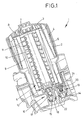
- Fig. 1
- insgesamt einen Querschnitt durch eine Kühlmittel-Pflege-Einheit eines ersten Ausführungsbeispiels,
- Fig. 2
- den Bereich des Sperrventils der Einheit von
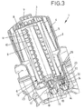
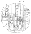
Fig. 1 in gegenüberFig. 1 vergrößertem Maßstab, die - Fig. 3 und 4
- Ansichten ähnlich den
Fig. 1 und2 , jedoch von einem zweiten Ausführungsbeispiel, und die - Fig. 5 und 6
- Ansichten ähnlich den
Fig. 1 und3 , jedoch von einem dritten Ausführungsbeispiel, mit zwei unterschiedlich weit aufgeschraubten Stellungen des Deckels. - In den
Fig. 1 und3 ist jeweils mit 1 insgesamt eine Kühlmittel-Pflege-Einheit bezeichnet. Diese weist ein becherartiges Gehäuse 2 auf sowie einen Deckel 3, der als Schraubdeckel ausgestaltet ist und mit dem Gehäuse 2 verschraubt ist. Zwischen Deckel 3 und Gehäuse 2 ist eine umlaufende O-Ringdichtung 4 vorgesehen. Der Deckel 3 weist einen Verdrängungskörper 5 auf, welcher verhindert, dass der Innenraum des Gehäuses 2 vollständig mit Kühlmittel gefüllt werden kann. Bei Entnahme des Deckels 3 vom Gehäuse 2 wird daher der Flüssigkeitsspiegel im Inneren des Gehäuses automatisch abgesenkt, so dass auch bei Schrägstellungen des Gehäuses 2 in einem im Betrieb üblichen Ausmaß sichergestellt ist, dass kein Kühlmittel über die Oberkante des Gehäuses 2 abfließen kann, sondern zuverlässig innerhalb des Gehäuses 2 verbleibt. - Mit dem Deckel 3 ist ein Filtereinsatz 6 verbunden, und zwar über eine Rastverbindung 7, die an einer oberen Endscheibe 8 des insgesamt im Wesentlichen zylindrisch ausgebildeten Filtereinsatzes 6 vorgesehen ist. Der Filtereinsatz 6 weist ein Filtermedium 9 in Form beispielsweise eines Papierfaltenfilters auf sowie einen inneren Stützdom 10, welcher Durchtrittsöffnungen 11 aufweist. An seinem unteren Ende weist der Filtereinsatz 6 eine untere Endscheibe 12 auf.
- Das Kühlmittel strömt durch einen Zulauf 14 radial außerhalb des Filtereinsatzes 6 in das Gehäuse 2 ein. Es gelangt nach Durchtritt durch das Filtermedium 9 in das Innere des Filtereinsatzes 6 und strömt dort durch einen Rücklauf 15 zurück. Im Rücklauf 15 ist ein Rückschlagventil 16 vorgesehen, mit einem als Kugel 17 ausgebildeten Ventilkörper. Das Rückschlagventil 16 ist als sogenanntes Schwimmerventil ausgebildet. Die Kugel 17 liegt bei dem in der Zeichnung dargestellten Betriebszustand einem unteren Anschlag 18 an. Sie kann durch die Wirkung ihres Auftriebs und durch den im übrigen Kühlmittelkreislauf herrschenden Druck angehoben und gegen ihren Ventilsitz gepresst werden, wenn der im Inneren des Gehäuses 2 und insbesondere im Inneren, auf der Reinseite des Filtereinsatzes 6 herrschende Druck entsprechend niedrig gegenüber dem Druck im übrigen Kühlmittelkreislauf unterhalb der Kugel 17 ist.
- Im Zulauf 14 ist ein insbesondere aus den
Fig. 2 und4 näher ersichtliches Sperrventil 19 vorgesehen. Dieses weist einen beweglichen Ventilkörper 20 auf sowie einen kragenförmigen Ventilsitz 21. Der Ventilkörper 20 ist mit einem Stößel 22 verbunden, gegen den die untere Endscheibe 12 anliegt. Die untere Endscheibe 12 ist bei dem Ausführungsbeispiel derFig. 3 und4 entlang ihrem äußeren Umfang durch eine untere umlaufende Wulst 23 verstärkt und auf diese Weise ausgesteift, so dass sie sich nicht unter dem Druck des Stößels 22 verformt und eine unzulässige Schließbewegung des Sperrventils 19 ermöglicht. Zudem bildet die Wulst 23 eine Führungsnut 25 aus, in welcher das obere Ende des Stößels 22 geführt ist. - Die Schließbewegung des Sperrventils 19 wird ermöglicht, wenn der Deckel 3 aus dem Gehäuse 2 herausgeschraubt wird. In diesem Fall bewegt sich auch der Filtereinsatz 6 mitsamt dem Deckel 3 bei der in der Zeichnung vorgesehenen Ausrichtung des Gehäuses 2 nach oben. Bei einer entsprechenden Vorspannung des Sperrventils 19 kann der Stößel 22 und damit der Ventilkörper 20 dieser Bewegung folgen, so dass der Ventilkörper 20 umso näher an den Ventilsitz 21 gerät, je weiter der Deckel 3 von dem Gehäuse 2 gelöst wird.
- Die erwähnte Vorspannung des Sperrventils 19 kann entweder durch eine Feder 24 bewirkt sein, wobei der Ventilkörper 20 gegen die Wirkung dieser Feder 24 durch den Filtereinsatz 6 in seiner Offenstellung gehalten wird, oder die erwähnte Vorspannung kann durch den im übrigen Kühlmittelkreislauf herrschenden Druck verwirklicht sein, welcher größer ist als der im Gehäuse 2 herrschende Druck, insbesondere, wenn das wirksame Innenvolumen des Gehäuses 2 vergrößert wird, indem der Deckel 3 abgeschraubt wird.
- Aufgrund dieser Druckdifferenz wird der Ventilkörper 20, selbst wenn die dargestellte Feder 24 nicht vorhanden wäre, in seine Schließstellung gedrückt. Sollte jedoch das Gehäuse 2 bei kaltem und insofern drucklosem Kühlmittel geöffnet werden, so würde das Sperrventil 19 nicht geschlossen werden, wenn der Ventilkörper 20 ausschließlich aufgrund des Innendrucks im Kühlmittelkreislauf in seine Schließstellung gedrängt würde. In einem derartigen Fall wäre jedoch auch das plötzliche Austreten heißen Kühlmittels nicht zu befürchten, so dass eine automatische, temperaturabhängige und selbstregelnde Funktion des Sperrventils 19 gegeben wäre.
- Unabhängig davon, ob die in der Zeichnung vorgesehene Feder 24 vorhanden ist oder nicht, handelt es sich bei dem Sperrventil 19 um ein wegbetätigtes Ventil, denn die Öffnungsstellung des Ventilkörpers 20 wird in jedem Fall wegabhängig von der Position des Filtereinsatzes erzwungen.
- Die Anordnung der am Deckel 3 vorgesehenen Dichtung 4 ist so weit von der Oberkante des Gehäuses 2 beabstandet vorgesehen, dass dieser Abstand größer ist als der Weg, welchen der Ventilkörper 20 aus seiner dargestellten Offenstellung bis in seine Schließstellung zurücklegen muss. Es ist daher sichergestellt, dass das Sperrventil 19 geschlossen ist, wenn während der Abnahme des Deckels 3 vom Gehäuse 2 die Dichtung 4 nach wie vor abdichtend wirksam ist. Erst im weiteren Verlauf dieser Abnahmebewegung des Deckels 3 gelangt die Dichtung 4 an die Oberkante des Gehäuses 2 und verliert ihre Wirksamkeit. In diesem Fall sind jedoch die Rückschlag- und Sperrventile 16 und 19 geschlossen und aufgrund des Verdrängungskörpers 5 ist auch zuverlässig sichergestellt, dass in dem Inneren des Gehäuses 2 kurz bevor die Dichtung 4 ihre Wirksamkeit verliert, kein Überdruck mehr herrscht, der zu einem plötzlichen Austreten heißen Kühlmittels führen könnte.
- Bei dem Ausführungsbeispiel der
Fig. 5 und6 sind gleiche bzw. gleichwirkende Bauelemente mit denselben Bezugsziffern versehen wie bei den Ausführungsbeispielen derFig. 1 - 4 . Nachfolgend wird lediglich auf die Merkmale Bezug genommen, in denen sich dieses dritte Ausführungsbeispiel von den beiden anderen Ausführungsbeispielen unterscheidet, so dass auch nur die im Zusammenhang damit relevanten Baugruppen bzw. Bauteile erwähnt und in den Zeichnungen mit Bezugsziffern versehen sind. -
Fig. 5 zeigt ein drittes Ausführungsbeispiel im betriebsbereiten Zustand, also mit vollständig in das Gehäuse 2 eingeschraubtem Deckel 3. Dabei ist der Verdrängerkörper 5 nicht radial außerhalb des Filtereinsatzes 6 vorgesehen, sondern ausschließlich oberhalb der oberen Endscheibe 8 des Filtereinsatzes 6. Hierdurch kann der radiale Bauraum innerhalb des Gehäuses 2 optimal genutzt werden, so dass entweder ein Filtereinsatz 6 mit sehr breiten Falten verwendet werden kann oder der Durchmesser des Gehäuses 2 vergleichsweise gering gehalten werden kann und auch unter räumlich beengten Verhältnissen noch an einer optimalen Stelle angeordnet werden kann. Die axiale Erstreckung der Kühlmittel-Pflege-Einheit 1 wird durch die Verlagerung des Verdrängungskörpers 5 axial vor den Filtereinsatz 6 zwar größer, jedoch ist in dieser Richtung üblicherweise ausreichend Freiraum vorhanden, da ohnehin für Wartungsarbeiten in dieser Richtung eine Zugänglichkeit zum Deckel 3 vorgesehen ist. - Beim Ausführungsbeispiel der
Fig. 5 und6 ist eine Entlüftungsleitung 26 im Deckel 3 verwirklicht, die zu einer entsprechenden Entlüftungsbohrung 27 in der oberen Endscheibe 8 des Filtereinsatzes 6 führt. Die Entlüftungsleitung 26 ist produktionstechnisch vorteilhaft nicht durch eine Bohrung verwirklicht, sondern durch eine oder mehrere Rippen an der Unterseite des Deckels 3, wo der Deckel 3 den Verdrängerkörper 5 bildet. Alternativ könnten derartige Entlüftungsleitungen durch Aussparungen, also Rillen in der Unterkante des Deckels 3 verwirklicht sein, oder auch durch entsprechende Rippen oder Rillen in der Oberfläche der oberen Endscheibe 8. Jedenfalls stellt die Entlüftungsleitung 26 einen Kurzschluss dar, also eine Umgehung des Filtereinsatzes 6, so dass ungereinigtes Kühlmittel unter Umgehung des Filtereinsatzes 6 durch die Entlüftungsbohrung 27 auf die Reinseite des Filters gelangen kann. Da der Filter jedoch ohnehin lediglich als Nebenstromfilter ausgelegt ist und lediglich einen Teil des insgesamt umgepumpten Kühlmittelfilters, stellt diese Umgehung des Filtereinsatzes 6 keine relevante Beeinträchtigung der Filterfunktion dar. - Links von der Entlüftungsleitung 26 ist in den
Fig. 5 und6 jeweils eine Bohrung 29 ersichtlich, welche sich durch den Deckel 3 erstreckt. Sie ermöglicht zusammen mit der Entlüftungsleitung 26 und der Entlüftungsbohrung 27 die Entlüftung des Gehäuses 2, wenn der Filtereinsatz 6 in das Gehäuse 2 eingesetzt wird und dabei die zunächst im Gehäuse 2 befindliche Luft verdrängt wird, Durch die Bohrung 29 kann die aus dem Gehäuse 2 verdrängte Luft solange entweichen, bis die Dichtung 4 gegen das Gehäuse 2 gerät und ihm abdichtend anliegt. - Das Sperrventil 19 ist bei dem Ausführungsbeispiel der
Fig. 5 und6 lediglich beispielsweise links vom Rücklauf-Sperrventil 16 dargestellt, also auf der im Vergleich zu den anderen Ausführungsbeispielen gegenüberliegenden Seite. - Der Ventilkörper 20 des Sperrventils 19 ist durch Rippen 28 in axialer Richtung geführt, wobei diese Rippen im Gehäuse 2 angeformt sind, so dass auf technisch einfache und wirtschaftlich vorteilhafte Weise die Führung des Ventilkörpers 20 sichergestellt wird.
- Die Länge des Gewindes zwischen Gehäuse 2 und Deckel 3 und die Lage der Dichtung 4 sind - wie insbesondere aus dem Vergleich zwischen den
Fig. 5 und6 hervorgeht - so aufeinander abgestimmt, dass das die Innen- und Außengewinde des Gehäuses 2 und des Deckels 3 miteinander kämmen, bevor der Dichtungsring an seiner im Gehäuse 2 vorgesehenen Dichtfläche anliegt. Auf diese Weise wird die Dichtung 4 beim Einschrauben des Deckels 3 in das Gehäuse 2 ebenfalls in das Gehäuse 2 eingezogen. Dies erleichtert einerseits die Handhabung beim Einschrauben des Deckels 3 und stellt zudem sicher, dass durch das Gewinde eine Art Zentrierung des Deckels 3 erfolgt, so dass eine möglichst gleichmäßige Anlage der Dichtung 4 ringsum an der zugeordneten Dichtfläche des Gehäuses 2 erfolgt und eine übermäßige, einseitige Belastung der Dichtung 4 vermieden wird, die gegebenenfalls zu einer Beschädigung der Dichtung führen könnte.
Claims (8)
- Kühlmittel-Pflege-Einheit (1) für das Kühlmittel einer Verbrennungskraftmaschine,
mit einem becherartigen Gehäuse (2),
einem das Gehäuse (2) verschließenden, entfernbaren Deckel (3),
einem in dem Gehäuse (2) angeordneten, auswechselbaren Filtereinsatz (6), welcher am Deckel (3) lösbar gehalten ist,
einem Zulauf (14) für ungefiltertes Kühlmittel,
sowie einem Rücklauf (15), welcher gefiltertes Kühlmittel zum übrigen Kühlmittelkreislauf führt,
wobei im Rücklauf (15) ein Rücklaufsperrventil (16) angeordnet ist, welches im bestimmungsgemäßen Betrieb des Filters geöffnet ist,
und dass im Zulauf (14) ein wegbetätigtes Sperrventil (19) angeordnet ist,
dadurch gekennzeichnet,
dass das Sperrventil (19) durch den Filtereinsatz (6) in seiner Offenstellung gehalten wird,
und bei Entnahme des Filtereinsatzes (6) aus dem Gehäuse (2) schließt, bevor der Deckel (3) vollständig vom Gehäuse (2) getrennt ist,
wobei eine am Deckel (3) vorgesehene Dichtung (4) so weit von der Oberkante des Gehäuses (2) beabstandet vorgesehen ist, dass dieser Abstand größer ist als der Weg, welchen ein Ventilkörper (20) des Sperrventils (19) aus seiner Offenstellung bis in seine Schließstellung zurücklegen muss
derart, dass die Dichtheit zwischen dem Deckel (3) und
dem Gehäuse (2) auch dann noch sichergestellt ist, wenn der Deckel (3) bereits teilweise vom Gehäuse (2) entfernt ist und dass während der Abnahmebewegung des Deckels (3) das Sperrventil (19) schließt und gleichzeitig nach außen hin das Innere des Filters abgedichtet ist,
und wobei erst nach einer Wegstrecke, die zuverlässig zum Schließen des Sperrventils (19) geführt hat, der Deckel (3) von dem Gehäuse (2) so weit freikommt, dass auch die Dichtung (4) nicht mehr zwischen Deckel (3) und Gehäuse (2) wirksam ist. - Kühlmittel-Pflege-Einheit nach Anspruch 1,
dadurch gekennzeichnet, dass der Filtereinsatz (6) im Wesentlichen zylindrisch ausgestaltet ist, mit einer dem Sperrventil (19) benachbarten Endscheibe (12), und dass die Endscheibe (12) auf den Ventilkörper (20) des Sperrventils (19) einwirkt. - Kühlmittel-Pflege-Einheit nach Anspruch 2,
gekennzeichnet durch einen Stößel (22), der an den Ventilkörper (20) anschließt und sich bis zur Endscheibe (12) erstreckt. - Kühlmittel-Pflege-Eihheit nach Anspruch 3,
gekennzeichnet durch eine an der Endscheibe (12) vorgesehene Führungsnut (25), in welcher der Stößel (22) geführt ist. - Kühlmittel-Pflege-Einheit nach einem der Ansprüche 2 bis 4, dadurch gekennzeichnet, dass die Endscheibe (12) in dem Bereich, der auf das Sperrventil (19) einwirkt verstärkt ist.
- Kühlmittel-Pflege-Einheit nach Anspruch 5,
gekennzeichnet durch einen umlaufende Wulst (23) an der Endscheibe. - Kühlmittel-Pflege-Einheit nach Anspruch 6,
dadurch gekennzeichnet, dass die Führungsnut (25) in der Wulst (23) ausgebildet ist. - Kühlmittel-Pflege-Einheit nach einem der vorhergehenden Ansprüche, dadurch gekennzeichnet, dass zwischen Deckel und Gehäuse eine Dichtung vorgesehen ist und dass sich Deckel und Gehäuse über eine bestimmte Strecke überlappen, derart, dass bei Abnahme des Deckels vom Gehäuse dieser Überlappungsbereich reduziert wird und das Sperrventil seine Schließstellung einnimmt, während sich der Deckel und das Gehäuse noch überlappen und die Dichtung noch zwischen diesen beiden, den Gehäuseinnenraum nach außen abdichtend, angeordnet ist.
Applications Claiming Priority (3)
| Application Number | Priority Date | Filing Date | Title |
|---|---|---|---|
| DE202004011104 | 2004-07-14 | ||
| DE202004017745U DE202004017745U1 (de) | 2004-07-14 | 2004-11-16 | Kühlmittel-Pflege-Einheit mit Rücklaufsperrventil |
| PCT/DE2005/001240 WO2006005331A1 (de) | 2004-07-14 | 2005-07-13 | Kühlmittel-pflege-einheit mit rücklaufsperrventil |
Publications (2)
| Publication Number | Publication Date |
|---|---|
| EP1766206A1 EP1766206A1 (de) | 2007-03-28 |
| EP1766206B1 true EP1766206B1 (de) | 2012-06-13 |
Family
ID=35063074
Family Applications (1)
| Application Number | Title | Priority Date | Filing Date |
|---|---|---|---|
| EP05767862A Expired - Lifetime EP1766206B1 (de) | 2004-07-14 | 2005-07-13 | Kühlmittel-pflege-einheit mit rücklaufsperrventil |
Country Status (4)
| Country | Link |
|---|---|
| US (1) | US8691090B2 (de) |
| EP (1) | EP1766206B1 (de) |
| DE (1) | DE202004017745U1 (de) |
| WO (1) | WO2006005331A1 (de) |
Families Citing this family (11)
| Publication number | Priority date | Publication date | Assignee | Title |
|---|---|---|---|---|
| DE202004017745U1 (de) | 2004-07-14 | 2006-03-23 | Hengst Gmbh & Co.Kg | Kühlmittel-Pflege-Einheit mit Rücklaufsperrventil |
| WO2011060413A1 (en) * | 2009-11-16 | 2011-05-19 | Cummins Filtration Ip Inc. | Combination relief valve and drainage mechanism requiring inserted element to permit drainage in a coalescer system |
| US20120223001A1 (en) * | 2011-03-04 | 2012-09-06 | Baldwin Filters, Inc. | Filter and center tube with helical fin |
| US8986539B2 (en) | 2011-04-19 | 2015-03-24 | Cummins Filtration Ip Inc. | Inside-out flow filter with pressure recovery |
| KR101583713B1 (ko) | 2014-11-13 | 2016-01-08 | 말레동현필터시스템 주식회사 | 회전형 드레인핀을 구비하는 오일필터모듈 |
| WO2017080606A1 (en) * | 2015-11-12 | 2017-05-18 | Mahle International Gmbh | Oil filter assembly having rotation type drain pin |
| US10913018B2 (en) | 2017-06-05 | 2021-02-09 | Baldwin Filters, Inc. | Spring biased filter element |
| DE102018221262A1 (de) * | 2018-12-07 | 2020-06-10 | Mahle International Gmbh | Filterelement für eine Filtereinrichtung |
| WO2021011452A1 (en) | 2019-07-16 | 2021-01-21 | Cummins Filtration Ip, Inc. | Filter cartridge with valve activation feature |
| US20230149838A1 (en) * | 2021-11-15 | 2023-05-18 | Entegris, Inc. | Filter cartridge, and method of retrofitting filter housing |
| EP4605105A1 (de) * | 2022-10-18 | 2025-08-27 | Cummins Filtration Inc. | Filter ohne filter und ohne durchfluss vom ventiltyp |
Family Cites Families (12)
| Publication number | Priority date | Publication date | Assignee | Title |
|---|---|---|---|---|
| US3682308A (en) * | 1970-12-03 | 1972-08-08 | White Motor Corp | Engine coolant filter |
| GB2208068B (en) * | 1987-04-02 | 1991-07-10 | Coopers Ap Filters Ltd | Fluid filter mounting |
| ATE103666T1 (de) * | 1989-10-04 | 1994-04-15 | Mann & Hummel Filter | Fluessigkeitsfilter fuer das schmieroel einer brennkraftmaschine. |
| DE4022723A1 (de) * | 1989-10-04 | 1991-04-11 | Mann & Hummel Filter | Fluessigkeitsfilter fuer das schmieroel einer brennkraftmaschine |
| DE4310492A1 (de) | 1993-03-31 | 1994-10-06 | Hydac Filtertechnik Gmbh | Filtervorrichtung mit Keyportanschluß |
| DE4322894A1 (de) * | 1993-07-09 | 1995-01-12 | Mann & Hummel Filter | Flüssigkeitsfilter |
| DE19540251C2 (de) * | 1995-10-28 | 1997-11-20 | Hengst Walter Gmbh & Co Kg | Kühlmittelfilter |
| US20020036162A1 (en) * | 1996-08-08 | 2002-03-28 | Magnusson Jan H. | Appliance with iodinated water source |
| US6488845B1 (en) | 1999-08-12 | 2002-12-03 | Purolator Products Na, Inc. | Oil filter unit with quick-drain valve actuator |
| DE10052101A1 (de) * | 2000-10-20 | 2002-05-02 | Mann & Hummel Filter | Flüssigkeitsfilter mit einem im Stützrohr des Filtereinsatzes angeordneten Ventil |
| DE20211448U1 (de) * | 2002-07-12 | 2003-11-20 | Hengst GmbH & Co.KG, 48147 Münster | Flüssigkeitsfilter |
| DE202004017745U1 (de) | 2004-07-14 | 2006-03-23 | Hengst Gmbh & Co.Kg | Kühlmittel-Pflege-Einheit mit Rücklaufsperrventil |
-
2004
- 2004-11-16 DE DE202004017745U patent/DE202004017745U1/de not_active Expired - Lifetime
-
2005
- 2005-07-13 US US11/572,182 patent/US8691090B2/en not_active Expired - Fee Related
- 2005-07-13 EP EP05767862A patent/EP1766206B1/de not_active Expired - Lifetime
- 2005-07-13 WO PCT/DE2005/001240 patent/WO2006005331A1/de not_active Ceased
Also Published As
| Publication number | Publication date |
|---|---|
| EP1766206A1 (de) | 2007-03-28 |
| DE202004017745U1 (de) | 2006-03-23 |
| WO2006005331A1 (de) | 2006-01-19 |
| US8691090B2 (en) | 2014-04-08 |
| US20080190832A1 (en) | 2008-08-14 |
Similar Documents
| Publication | Publication Date | Title |
|---|---|---|
| EP1137470B1 (de) | Fluidfilter mit gehäusefestem ablassdom | |
| EP1110590B1 (de) | Flüssigkeitsfilter mit Ablass für Flüssigkeitsrückstände | |
| DE102009050696B4 (de) | Wärmetauscher-Einheit mit Umgehungsventil | |
| EP3268106B1 (de) | Filter mit einem filterumgehungsventil und filtereinsatz dafür | |
| EP2445604B1 (de) | Filtereinrichtung | |
| WO2007128306A2 (de) | Flüssigkeitsfilter mit rücklaufsperrventil im reinseitigen strömungskanal | |
| EP3641909B1 (de) | Filtersystem mit filterelement und sekundärelement zum verschliesen eines mittelrohrs | |
| EP1766206B1 (de) | Kühlmittel-pflege-einheit mit rücklaufsperrventil | |
| EP3380211B1 (de) | Filterkartusche für einen ölfilter eines kraftwagens und ölfilter | |
| WO2014082762A1 (de) | Filter, filterelement, filtergehäuse und ablassvorrichtung eines filters | |
| EP3366363B1 (de) | Abscheidevorrichtung zur abscheidung eines fluids aus gas sowie abscheideelement und verbindungselement für eine diesbezügliche abscheidevorrichtung | |
| WO2013178680A1 (de) | Filtereinrichtung | |
| EP2502657B1 (de) | Filtervorrichtung | |
| DE19961579A1 (de) | Flüssigkeitsfilter mit einem Kühler | |
| DE29915844U1 (de) | Filter mit Ventil-Kombinationsbauteil | |
| DE202005007872U1 (de) | Filtereinrichtung, insbesondere zur Flüssigkeitsfilterung in Brennkraftmaschinen | |
| DE112014005489B4 (de) | Filtereinrichtung, insbesondere Flüssigkeitsfilter, Filterelement und Adapterteil | |
| EP2808071B1 (de) | Filtereinrichtung, insbesondere für ein Kraftfahrzeug | |
| EP1671692B1 (de) | Flüssigkeitswechselfilter mit Rücklaufsperrventil | |
| EP1194206B1 (de) | Filter, sowie filtereinsatz dafür, mit direktdichtung | |
| EP2653675B1 (de) | Ölfilter einer Brennkraftmaschine und Ölfilterelement eines Ölfilters | |
| WO2016058691A1 (de) | Filterelement für eine filtereinrichtung einer verbrennungskraftmaschine sowie filtereinrichtung für eine verbrennungskraftmaschine | |
| EP2357030B1 (de) | Filtervorrichtung, insbesondere Rücklaufsaugfilter | |
| DE102016000339B4 (de) | Filterelement und Filtersystem für ein Flüssigmedium mit rein- und rohseitiger Entlüftung | |
| WO2015022138A1 (de) | Flüssigkeitsfilter, insbesondere kraftstofffilter |
Legal Events
| Date | Code | Title | Description |
|---|---|---|---|
| PUAI | Public reference made under article 153(3) epc to a published international application that has entered the european phase |
Free format text: ORIGINAL CODE: 0009012 |
|
| 17P | Request for examination filed |
Effective date: 20070117 |
|
| AK | Designated contracting states |
Kind code of ref document: A1 Designated state(s): AT BE BG CH CY CZ DE DK EE ES FI FR GB GR HU IE IS IT LI LT LU LV MC NL PL PT RO SE SI SK TR |
|
| DAX | Request for extension of the european patent (deleted) | ||
| 17Q | First examination report despatched |
Effective date: 20100723 |
|
| GRAP | Despatch of communication of intention to grant a patent |
Free format text: ORIGINAL CODE: EPIDOSNIGR1 |
|
| GRAS | Grant fee paid |
Free format text: ORIGINAL CODE: EPIDOSNIGR3 |
|
| GRAA | (expected) grant |
Free format text: ORIGINAL CODE: 0009210 |
|
| AK | Designated contracting states |
Kind code of ref document: B1 Designated state(s): AT BE BG CH CY CZ DE DK EE ES FI FR GB GR HU IE IS IT LI LT LU LV MC NL PL PT RO SE SI SK TR |
|
| REG | Reference to a national code |
Ref country code: GB Ref legal event code: FG4D Free format text: NOT ENGLISH |
|
| REG | Reference to a national code |
Ref country code: CH Ref legal event code: EP Ref country code: AT Ref legal event code: REF Ref document number: 562118 Country of ref document: AT Kind code of ref document: T Effective date: 20120615 |
|
| REG | Reference to a national code |
Ref country code: IE Ref legal event code: FG4D Free format text: LANGUAGE OF EP DOCUMENT: GERMAN |
|
| REG | Reference to a national code |
Ref country code: DE Ref legal event code: R096 Ref document number: 502005012827 Country of ref document: DE Effective date: 20120809 |
|
| REG | Reference to a national code |
Ref country code: NL Ref legal event code: VDEP Effective date: 20120613 |
|
| PG25 | Lapsed in a contracting state [announced via postgrant information from national office to epo] |
Ref country code: FI Free format text: LAPSE BECAUSE OF FAILURE TO SUBMIT A TRANSLATION OF THE DESCRIPTION OR TO PAY THE FEE WITHIN THE PRESCRIBED TIME-LIMIT Effective date: 20120613 Ref country code: CY Free format text: LAPSE BECAUSE OF FAILURE TO SUBMIT A TRANSLATION OF THE DESCRIPTION OR TO PAY THE FEE WITHIN THE PRESCRIBED TIME-LIMIT Effective date: 20120613 Ref country code: LT Free format text: LAPSE BECAUSE OF FAILURE TO SUBMIT A TRANSLATION OF THE DESCRIPTION OR TO PAY THE FEE WITHIN THE PRESCRIBED TIME-LIMIT Effective date: 20120613 Ref country code: SE Free format text: LAPSE BECAUSE OF FAILURE TO SUBMIT A TRANSLATION OF THE DESCRIPTION OR TO PAY THE FEE WITHIN THE PRESCRIBED TIME-LIMIT Effective date: 20120613 |
|
| REG | Reference to a national code |
Ref country code: LT Ref legal event code: MG4D Effective date: 20120613 |
|
| PG25 | Lapsed in a contracting state [announced via postgrant information from national office to epo] |
Ref country code: LV Free format text: LAPSE BECAUSE OF FAILURE TO SUBMIT A TRANSLATION OF THE DESCRIPTION OR TO PAY THE FEE WITHIN THE PRESCRIBED TIME-LIMIT Effective date: 20120613 Ref country code: SI Free format text: LAPSE BECAUSE OF FAILURE TO SUBMIT A TRANSLATION OF THE DESCRIPTION OR TO PAY THE FEE WITHIN THE PRESCRIBED TIME-LIMIT Effective date: 20120613 Ref country code: GR Free format text: LAPSE BECAUSE OF FAILURE TO SUBMIT A TRANSLATION OF THE DESCRIPTION OR TO PAY THE FEE WITHIN THE PRESCRIBED TIME-LIMIT Effective date: 20120914 |
|
| BERE | Be: lapsed |
Owner name: HENGST G.M.B.H. & CO. KG Effective date: 20120731 |
|
| PG25 | Lapsed in a contracting state [announced via postgrant information from national office to epo] |
Ref country code: EE Free format text: LAPSE BECAUSE OF FAILURE TO SUBMIT A TRANSLATION OF THE DESCRIPTION OR TO PAY THE FEE WITHIN THE PRESCRIBED TIME-LIMIT Effective date: 20120613 Ref country code: RO Free format text: LAPSE BECAUSE OF FAILURE TO SUBMIT A TRANSLATION OF THE DESCRIPTION OR TO PAY THE FEE WITHIN THE PRESCRIBED TIME-LIMIT Effective date: 20120613 Ref country code: CZ Free format text: LAPSE BECAUSE OF FAILURE TO SUBMIT A TRANSLATION OF THE DESCRIPTION OR TO PAY THE FEE WITHIN THE PRESCRIBED TIME-LIMIT Effective date: 20120613 Ref country code: SK Free format text: LAPSE BECAUSE OF FAILURE TO SUBMIT A TRANSLATION OF THE DESCRIPTION OR TO PAY THE FEE WITHIN THE PRESCRIBED TIME-LIMIT Effective date: 20120613 Ref country code: IS Free format text: LAPSE BECAUSE OF FAILURE TO SUBMIT A TRANSLATION OF THE DESCRIPTION OR TO PAY THE FEE WITHIN THE PRESCRIBED TIME-LIMIT Effective date: 20121013 |
|
| PG25 | Lapsed in a contracting state [announced via postgrant information from national office to epo] |
Ref country code: IT Free format text: LAPSE BECAUSE OF FAILURE TO SUBMIT A TRANSLATION OF THE DESCRIPTION OR TO PAY THE FEE WITHIN THE PRESCRIBED TIME-LIMIT Effective date: 20120613 Ref country code: PT Free format text: LAPSE BECAUSE OF FAILURE TO SUBMIT A TRANSLATION OF THE DESCRIPTION OR TO PAY THE FEE WITHIN THE PRESCRIBED TIME-LIMIT Effective date: 20121015 Ref country code: MC Free format text: LAPSE BECAUSE OF NON-PAYMENT OF DUE FEES Effective date: 20120731 Ref country code: PL Free format text: LAPSE BECAUSE OF FAILURE TO SUBMIT A TRANSLATION OF THE DESCRIPTION OR TO PAY THE FEE WITHIN THE PRESCRIBED TIME-LIMIT Effective date: 20120613 |
|
| REG | Reference to a national code |
Ref country code: CH Ref legal event code: PL |
|
| PG25 | Lapsed in a contracting state [announced via postgrant information from national office to epo] |
Ref country code: NL Free format text: LAPSE BECAUSE OF FAILURE TO SUBMIT A TRANSLATION OF THE DESCRIPTION OR TO PAY THE FEE WITHIN THE PRESCRIBED TIME-LIMIT Effective date: 20120613 |
|
| PLBE | No opposition filed within time limit |
Free format text: ORIGINAL CODE: 0009261 |
|
| STAA | Information on the status of an ep patent application or granted ep patent |
Free format text: STATUS: NO OPPOSITION FILED WITHIN TIME LIMIT |
|
| REG | Reference to a national code |
Ref country code: FR Ref legal event code: ST Effective date: 20130329 |
|
| PG25 | Lapsed in a contracting state [announced via postgrant information from national office to epo] |
Ref country code: FR Free format text: LAPSE BECAUSE OF NON-PAYMENT OF DUE FEES Effective date: 20120813 Ref country code: ES Free format text: LAPSE BECAUSE OF FAILURE TO SUBMIT A TRANSLATION OF THE DESCRIPTION OR TO PAY THE FEE WITHIN THE PRESCRIBED TIME-LIMIT Effective date: 20120924 Ref country code: DK Free format text: LAPSE BECAUSE OF FAILURE TO SUBMIT A TRANSLATION OF THE DESCRIPTION OR TO PAY THE FEE WITHIN THE PRESCRIBED TIME-LIMIT Effective date: 20120613 Ref country code: CH Free format text: LAPSE BECAUSE OF NON-PAYMENT OF DUE FEES Effective date: 20120731 Ref country code: LI Free format text: LAPSE BECAUSE OF NON-PAYMENT OF DUE FEES Effective date: 20120731 |
|
| REG | Reference to a national code |
Ref country code: IE Ref legal event code: MM4A |
|
| 26N | No opposition filed |
Effective date: 20130314 |
|
| GBPC | Gb: european patent ceased through non-payment of renewal fee |
Effective date: 20120913 |
|
| PG25 | Lapsed in a contracting state [announced via postgrant information from national office to epo] |
Ref country code: BE Free format text: LAPSE BECAUSE OF NON-PAYMENT OF DUE FEES Effective date: 20120731 |
|
| REG | Reference to a national code |
Ref country code: DE Ref legal event code: R097 Ref document number: 502005012827 Country of ref document: DE Effective date: 20130314 |
|
| PG25 | Lapsed in a contracting state [announced via postgrant information from national office to epo] |
Ref country code: GB Free format text: LAPSE BECAUSE OF NON-PAYMENT OF DUE FEES Effective date: 20120913 Ref country code: IE Free format text: LAPSE BECAUSE OF NON-PAYMENT OF DUE FEES Effective date: 20120713 |
|
| REG | Reference to a national code |
Ref country code: AT Ref legal event code: MM01 Ref document number: 562118 Country of ref document: AT Kind code of ref document: T Effective date: 20120731 |
|
| PG25 | Lapsed in a contracting state [announced via postgrant information from national office to epo] |
Ref country code: AT Free format text: LAPSE BECAUSE OF NON-PAYMENT OF DUE FEES Effective date: 20120731 |
|
| PG25 | Lapsed in a contracting state [announced via postgrant information from national office to epo] |
Ref country code: TR Free format text: LAPSE BECAUSE OF FAILURE TO SUBMIT A TRANSLATION OF THE DESCRIPTION OR TO PAY THE FEE WITHIN THE PRESCRIBED TIME-LIMIT Effective date: 20120613 |
|
| PG25 | Lapsed in a contracting state [announced via postgrant information from national office to epo] |
Ref country code: LU Free format text: LAPSE BECAUSE OF NON-PAYMENT OF DUE FEES Effective date: 20120713 |
|
| PG25 | Lapsed in a contracting state [announced via postgrant information from national office to epo] |
Ref country code: HU Free format text: LAPSE BECAUSE OF FAILURE TO SUBMIT A TRANSLATION OF THE DESCRIPTION OR TO PAY THE FEE WITHIN THE PRESCRIBED TIME-LIMIT Effective date: 20050713 |
|
| REG | Reference to a national code |
Ref country code: DE Ref legal event code: R082 Ref document number: 502005012827 Country of ref document: DE Representative=s name: HABBEL & HABBEL, DE |
|
| REG | Reference to a national code |
Ref country code: DE Ref legal event code: R081 Ref document number: 502005012827 Country of ref document: DE Owner name: HENGST SE & CO. KG, DE Free format text: FORMER OWNER: HENGST GMBH & CO. KG, 48147 MUENSTER, DE Effective date: 20141118 Ref country code: DE Ref legal event code: R081 Ref document number: 502005012827 Country of ref document: DE Owner name: HENGST SE & CO. KG, DE Free format text: FORMER OWNER: HENGST GMBH & CO. KG, 48147 MUENSTER, DE Effective date: 20120618 Ref country code: DE Ref legal event code: R082 Ref document number: 502005012827 Country of ref document: DE Representative=s name: HABBEL & HABBEL, DE Effective date: 20141118 Ref country code: DE Ref legal event code: R082 Ref document number: 502005012827 Country of ref document: DE Representative=s name: HABBEL UND HABBEL PATENTANWAELTE PARTG MBB, DE Effective date: 20141118 Ref country code: DE Ref legal event code: R081 Ref document number: 502005012827 Country of ref document: DE Owner name: HENGST SE, DE Free format text: FORMER OWNER: HENGST GMBH & CO. KG, 48147 MUENSTER, DE Effective date: 20120618 Ref country code: DE Ref legal event code: R081 Ref document number: 502005012827 Country of ref document: DE Owner name: HENGST SE, DE Free format text: FORMER OWNER: HENGST GMBH & CO. KG, 48147 MUENSTER, DE Effective date: 20141118 |
|
| REG | Reference to a national code |
Ref country code: DE Ref legal event code: R082 Ref document number: 502005012827 Country of ref document: DE Representative=s name: HABBEL UND HABBEL PATENTANWAELTE PARTG MBB, DE Ref country code: DE Ref legal event code: R081 Ref document number: 502005012827 Country of ref document: DE Owner name: HENGST SE, DE Free format text: FORMER OWNER: HENGST SE & CO. KG, 48147 MUENSTER, DE |
|
| PGFP | Annual fee paid to national office [announced via postgrant information from national office to epo] |
Ref country code: DE Payment date: 20190711 Year of fee payment: 15 |
|
| PGFP | Annual fee paid to national office [announced via postgrant information from national office to epo] |
Ref country code: BG Payment date: 20190722 Year of fee payment: 15 |
|
| REG | Reference to a national code |
Ref country code: DE Ref legal event code: R119 Ref document number: 502005012827 Country of ref document: DE |
|
| PG25 | Lapsed in a contracting state [announced via postgrant information from national office to epo] |
Ref country code: DE Free format text: LAPSE BECAUSE OF NON-PAYMENT OF DUE FEES Effective date: 20210202 Ref country code: BG Free format text: LAPSE BECAUSE OF NON-PAYMENT OF DUE FEES Effective date: 20210131 |