EP1766237B1 - Einflügelvakuumpumpe - Google Patents
Einflügelvakuumpumpe Download PDFInfo
- Publication number
- EP1766237B1 EP1766237B1 EP05731506A EP05731506A EP1766237B1 EP 1766237 B1 EP1766237 B1 EP 1766237B1 EP 05731506 A EP05731506 A EP 05731506A EP 05731506 A EP05731506 A EP 05731506A EP 1766237 B1 EP1766237 B1 EP 1766237B1
- Authority
- EP
- European Patent Office
- Prior art keywords
- blade
- vacuum pump
- pump according
- wing
- section
- Prior art date
- Legal status (The legal status is an assumption and is not a legal conclusion. Google has not performed a legal analysis and makes no representation as to the accuracy of the status listed.)
- Expired - Lifetime
Links
- 238000007789 sealing Methods 0.000 claims description 3
- 230000007704 transition Effects 0.000 claims description 3
- 230000002093 peripheral effect Effects 0.000 description 14
- 238000002347 injection Methods 0.000 description 2
- 239000007924 injection Substances 0.000 description 2
- 230000001050 lubricating effect Effects 0.000 description 2
- 239000002184 metal Substances 0.000 description 2
- 238000010276 construction Methods 0.000 description 1
- 238000013461 design Methods 0.000 description 1
- 238000011161 development Methods 0.000 description 1
- 230000018109 developmental process Effects 0.000 description 1
- 238000006073 displacement reaction Methods 0.000 description 1
- 239000010687 lubricating oil Substances 0.000 description 1
- 238000012423 maintenance Methods 0.000 description 1
- 238000004519 manufacturing process Methods 0.000 description 1
- 238000003801 milling Methods 0.000 description 1
- 238000012545 processing Methods 0.000 description 1
- 239000000243 solution Substances 0.000 description 1
- 239000013585 weight reducing agent Substances 0.000 description 1
Images


Classifications
-
- F—MECHANICAL ENGINEERING; LIGHTING; HEATING; WEAPONS; BLASTING
- F04—POSITIVE - DISPLACEMENT MACHINES FOR LIQUIDS; PUMPS FOR LIQUIDS OR ELASTIC FLUIDS
- F04C—ROTARY-PISTON, OR OSCILLATING-PISTON, POSITIVE-DISPLACEMENT MACHINES FOR LIQUIDS; ROTARY-PISTON, OR OSCILLATING-PISTON, POSITIVE-DISPLACEMENT PUMPS
- F04C18/00—Rotary-piston pumps specially adapted for elastic fluids
- F04C18/30—Rotary-piston pumps specially adapted for elastic fluids having the characteristics covered by two or more of groups F04C18/02, F04C18/08, F04C18/22, F04C18/24, F04C18/48, or having the characteristics covered by one of these groups together with some other type of movement between co-operating members
- F04C18/34—Rotary-piston pumps specially adapted for elastic fluids having the characteristics covered by two or more of groups F04C18/02, F04C18/08, F04C18/22, F04C18/24, F04C18/48, or having the characteristics covered by one of these groups together with some other type of movement between co-operating members having the movement defined in group F04C18/08 or F04C18/22 and relative reciprocation between the co-operating members
- F04C18/344—Rotary-piston pumps specially adapted for elastic fluids having the characteristics covered by two or more of groups F04C18/02, F04C18/08, F04C18/22, F04C18/24, F04C18/48, or having the characteristics covered by one of these groups together with some other type of movement between co-operating members having the movement defined in group F04C18/08 or F04C18/22 and relative reciprocation between the co-operating members with vanes reciprocating with respect to the inner member
-
- F—MECHANICAL ENGINEERING; LIGHTING; HEATING; WEAPONS; BLASTING
- F01—MACHINES OR ENGINES IN GENERAL; ENGINE PLANTS IN GENERAL; STEAM ENGINES
- F01C—ROTARY-PISTON OR OSCILLATING-PISTON MACHINES OR ENGINES
- F01C21/00—Component parts, details or accessories not provided for in groups F01C1/00 - F01C20/00
- F01C21/08—Rotary pistons
- F01C21/0809—Construction of vanes or vane holders
-
- F—MECHANICAL ENGINEERING; LIGHTING; HEATING; WEAPONS; BLASTING
- F01—MACHINES OR ENGINES IN GENERAL; ENGINE PLANTS IN GENERAL; STEAM ENGINES
- F01C—ROTARY-PISTON OR OSCILLATING-PISTON MACHINES OR ENGINES
- F01C21/00—Component parts, details or accessories not provided for in groups F01C1/00 - F01C20/00
- F01C21/08—Rotary pistons
- F01C21/0809—Construction of vanes or vane holders
- F01C21/0881—Construction of vanes or vane holders the vanes consisting of two or more parts
-
- F—MECHANICAL ENGINEERING; LIGHTING; HEATING; WEAPONS; BLASTING
- F04—POSITIVE - DISPLACEMENT MACHINES FOR LIQUIDS; PUMPS FOR LIQUIDS OR ELASTIC FLUIDS
- F04C—ROTARY-PISTON, OR OSCILLATING-PISTON, POSITIVE-DISPLACEMENT MACHINES FOR LIQUIDS; ROTARY-PISTON, OR OSCILLATING-PISTON, POSITIVE-DISPLACEMENT PUMPS
- F04C18/00—Rotary-piston pumps specially adapted for elastic fluids
- F04C18/30—Rotary-piston pumps specially adapted for elastic fluids having the characteristics covered by two or more of groups F04C18/02, F04C18/08, F04C18/22, F04C18/24, F04C18/48, or having the characteristics covered by one of these groups together with some other type of movement between co-operating members
- F04C18/34—Rotary-piston pumps specially adapted for elastic fluids having the characteristics covered by two or more of groups F04C18/02, F04C18/08, F04C18/22, F04C18/24, F04C18/48, or having the characteristics covered by one of these groups together with some other type of movement between co-operating members having the movement defined in group F04C18/08 or F04C18/22 and relative reciprocation between the co-operating members
- F04C18/344—Rotary-piston pumps specially adapted for elastic fluids having the characteristics covered by two or more of groups F04C18/02, F04C18/08, F04C18/22, F04C18/24, F04C18/48, or having the characteristics covered by one of these groups together with some other type of movement between co-operating members having the movement defined in group F04C18/08 or F04C18/22 and relative reciprocation between the co-operating members with vanes reciprocating with respect to the inner member
- F04C18/3441—Rotary-piston pumps specially adapted for elastic fluids having the characteristics covered by two or more of groups F04C18/02, F04C18/08, F04C18/22, F04C18/24, F04C18/48, or having the characteristics covered by one of these groups together with some other type of movement between co-operating members having the movement defined in group F04C18/08 or F04C18/22 and relative reciprocation between the co-operating members with vanes reciprocating with respect to the inner member the inner and outer member being in contact along one line or continuous surface substantially parallel to the axis of rotation
-
- F—MECHANICAL ENGINEERING; LIGHTING; HEATING; WEAPONS; BLASTING
- F04—POSITIVE - DISPLACEMENT MACHINES FOR LIQUIDS; PUMPS FOR LIQUIDS OR ELASTIC FLUIDS
- F04C—ROTARY-PISTON, OR OSCILLATING-PISTON, POSITIVE-DISPLACEMENT MACHINES FOR LIQUIDS; ROTARY-PISTON, OR OSCILLATING-PISTON, POSITIVE-DISPLACEMENT PUMPS
- F04C2220/00—Application
- F04C2220/10—Vacuum
Definitions
- the invention relates to a single-wing vacuum pump with a cup-shaped housing, a rotor rotatably mounted eccentrically in the housing, a rotatably mounted in the rotor orthogonal to the axis of rotation and a wing receiving working space with an inner peripheral surface, against which the two opposite sealing edges of the wing, wherein the Wing divided the working space into a suction chamber and a pressure chamber.
- Vacuum pumps of such a construction are known ( DE 100 46 697 A1 or DE 3913989 A1 ). As a rule, they serve to provide a vacuum for a vacuum consumer, for example in a motor vehicle, by causing the rotor to rotate and sucking air out of a vacuum line via the suction space.
- the working space of this vane pump is designed so that the wing with its two opposite ends on the inner peripheral surface slides along. The wing separates the suction chamber, which is connected to the suction port, from the pressure chamber, which is connected to the pressure port. In order to achieve a high degree of efficiency, the wing must be permanently attached to the inner peripheral surface, since the suction chamber is otherwise ventilated.
- a known solution proposes to build the wing in two parts and to insert a spring between the two wing parts, which urges the two wing parts outward in the direction of the peripheral surface. This will ensures that the sealing edges of the wing permanently on the inner peripheral surface.
- a disadvantage is considered that this wing is subject to considerable wear due to the contact pressure, which not only reduces the efficiency, but also maintenance intervals are shortened.
- a vane pump has become known in which a plurality of blades are arranged eccentrically in the rotor. The wings are acted upon at their wing tip and the wing bottom with the pressure prevailing in the pressure chamber.
- a lubricating device for fast-running rotary body is known in which the lubricating film distributing wing is chamfered on its front.
- the invention is therefore based on the object to provide a single-wing vacuum pump, which has a better efficiency.
- the ends of the wing are cylindrically rounded and abut on a central contact or surface line of the cylinder on the inner peripheral surface of the working space.
- the end of the wing is partially flattened on the pressure side, whereby the pressure forces acting on the wing are changed in their direction.
- the flattened section increases the radial component of the compressive force which counteracts the centrifugal force of the wing.
- the centrifugal force of the wing connecting the wing to the peripheral surface presses the working space, so is reduced by the opposing pressure force from the pressure chamber. The wing is thus pressed less strongly against the peripheral surface.
- the surfaces bounding the section or adjacent to the section are partially cylindrical. This provides the advantage that the contact line can relatively easily move along the surface of the wing tip. Since the angle of attack of the wing during a complete revolution of the rotor is constantly changing, and the contact line of the wing tip migrates slightly, the cylindrical design of the wing tip ensures uniform wear.
- the flattened portion is planar.
- Such trained wing tips are relatively easy to produce, since this flattened portion, for example, attached by a milling process, can be produced.
- the section has a deviating from 0 ° angle to the longitudinal surface of the wing.
- the wing is located off-center on the inner peripheral surface.
- the contact line thus has a distance to the median plane of the wing, whereby the advantage is achieved that the flattened portion can be made larger. As a result, the tangential component of the compressive force can be further reduced.
- a harmonious course and thus a simple production of the wing tip is achieved in that the surfaces on the wing tip steadily pass into the flattened section.
- the surfaces and the section at the transition points can have the same tangents exhibit.
- the processing tools can produce the wing tip in a single operation or can be easily and inexpensively manufactured in an injection-molded wing tip injection mold.
- the wing has a wing body and two terminal attachments. At these essays of the flattened portion is formed and these essays are applied to the inner peripheral surface of the working space.
- the attachments may preferably be made of plastic, whereas the wing body is made of metal, for example.
- the wing body is a die-cast or injection-molded element and the attachments are injection-molded.
- the wing body at its the tips receiving ends each have a slot which is orthogonal to the longitudinal broad side of the wing body.
- the article has a U-shaped or C-shaped cross-section formed by two parallel legs.
- the legs flank a ridge, wherein the legs are formed semicircular even at its free end and engage in a corresponding semi-circular Auf founded at the ends of the wing body.
- Both the bridge and shank mountings prevent the attachments from making undefined movements during pump operation. In particular, a flutter or rattle is prevented In addition, noise developments are prevented.
- the essays are pushed under low bias on the ends of the wing body.
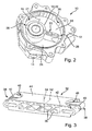
- FIG. 1 is denoted by the reference numeral 10, a vacuum pump, in which the housing 12 is shown without housing cover.
- the housing 12 has a suction port 14, which opens into an interior 16.
- this interior 16 is a generally designated 18 rotor in which a wing 20 is mounted orthogonal to the axis of rotation 21 slidably ..
- the wing 20 divides the working chamber 22 formed by the interior 18 in a suction chamber 24 and a pressure chamber 26.
- the wing 20 is located with its two ends 28 on a working space 22 surrounding inner peripheral surface 30 at.
- the wing 20 is how out FIG. 1 can be seen, formed by a wing body 32 and two essays 34.
- the FIG. 3 shows the wing body 32, wherein the FIG. 4 one of the essays 34 reflects.
- the wing body 32 is made of metal in the embodiment and is a die-cast part, but it may also be injection-molded.
- the article 34 is made of plastic and is injection molded.
- cavities 36 which are designed either continuously or as a blind hole.
- the wing body 32 each have a slot 40 which extends on the one hand in the direction of the longitudinal axis 42 of the wing 20, on the other hand orthogonal to the broad side surface 44.
- the longitudinal axis 42 of the wing 20 is located between the two broad side surfaces 44 and the contact line 68 is located between the longitudinal center plane 70 and the suction side 42 facing broad side surface 44th
- the two broad side surfaces 44 are provided in the region of the ends 38 with substantially semicircular recesses 46, in which leg 48 (see FIG. 4 ) of Attachment 34 can be inserted.
- the two legs 48 flank a web 50, which also extends in the direction of the longitudinal axis 42 of the wing 20 and has the shape of the slot 40. Both the slot 40 with web 50 and the recess 46 prevent the attachment 34 can be displaced in the direction of the axis 52.
- the legs 48 engaging around the end 38 prevent the attachment 34 from dodging in the direction of the axis 54. This means that the attachment 34 is fastened on the wing body 32 so as to be displaceable only in the direction of the longitudinal axis 42.
- FIG. 5 is a plan view of the wing body 32 with attached attachment 34 shown.
- the attachment 34 touches the inner peripheral surface 30, so that the suction chamber 24 are below and the pressure chamber 26 above the wing 20.
- the vane 20 rotates in the direction of the arrow 56 and, at its rear side facing the suction space 24, merges into the broad side surface 44 of the wing 20 at an angle different from the 90 °.
- the attachment 34 has a flattened portion 66, on which the pressure force 60 acts.
- This pressure force 60 is composed of the pressure force 58 and an additional pressure force 62, which arises because the contact line 68 has a distance A from the center plane 70 of the wing 20. Since the pressure force 60 actually acting on the wing 20 due to the displacement of the contact line 68 is greater than the pressure force 58 in a conventional wing, and also the negative pressure in the suction chamber 24th originating forces 74 are smaller than in a conventional wing, the contact pressure at the contact line 68 is substantially reduced, whereby the wear is reduced.
- the contact line 38 is located on a partially cylindrical portion 72 of the attachment 34.
- the partially cylindrical portion 72 is continuous with the same tangent in the flat portion 66 on.
Landscapes
- Engineering & Computer Science (AREA)
- Mechanical Engineering (AREA)
- General Engineering & Computer Science (AREA)
- Rotary Pumps (AREA)
- Applications Or Details Of Rotary Compressors (AREA)
- Compressors, Vaccum Pumps And Other Relevant Systems (AREA)
Description
- Die Erfindung betrifft eine Einflügelvakuumpumpe mit einem topfförmigen Gehäuse, einem exzentrisch im Gehäuse drehbar gelagerten Rotor, einem im Rotor orthogonal zur Drehachse verschieblich gelagerten Flügel und einem den Flügel aufnehmenden Arbeitsraum mit einer Innenumfangsfläche, an welcher die beiden einander gegenüberliegenden Dichtkanten des Flügels anliegen, wobei der Flügel den Arbeitsraum in einen Saugraum und einen Druckraum unterteilt.
- Vakuumpumpen mit einem derartigen Aufbau sind bekannt (
DE 100 46 697 A1 oderDE 3913989 A1 ). Sie dienen in der Regel dazu, für einen Unterdruckverbraucher, zum Beispiel in einem Kraftfahrzeug, einen Unterdruck bereit zu stellen, indem der Rotor in Drehung versetzt wird und über den Saugraum Luft aus einer Unterdruckleitung abgesaugt wird. Der Arbeitsraum dieser Flügelzellenpumpe ist so gestaltet, dass der Flügel mit seinen beiden einander gegenüberliegenden Enden an der Innenumfangsfläche entlang gleitet. Der Flügel trennt dabei den Saugraum, der mit dem Sauganschluss verbunden ist, vom Druckraum, der mit dem Druckanschluss verbunden ist. Um einen hohen Wirkungsgrad zu erzielen, muss der Flügel permanent an der Innenumfangsfläche anliegen, da der Saugraum ansonsten belüftet wird. - Eine bekannte Lösung schlägt dabei vor, den Flügel zweiteilig aufzubauen und zwischen die beiden Flügelteile eine Feder einzusetzen, die die beiden Flügelteile nach außen in Richtung der Umfangsfläche drängt. Dadurch wird gewährleistet, dass die Dichtkanten des Flügels permanent an der Innenumfangsfläche anliegen. Als nachteilig wird aber angesehen, dass dieser Flügel aufgrund des Anpressdrucks einem erheblichen Verschleiß unterliegt, wodurch nicht nur der Wirkungsgrad sinkt, sondern auch Wartungsintervalle verkürzt werden.
- Aus der
DE 43 32 540 A1 ist eine Flügelzellenpumpe bekannt geworden, bei der im Rotor mehrere Flügel exzentrisch angeordnet sind. Die Flügel werden an ihrer Flügelspitze und am Flügelgrund mit dem im Druckraum herrschenden Druck beaufschlagt. Aus derDE-PS 364 107 ist eine Schmiervorrichtung für schnell laufende Drehkörper bekannt, bei der der den Schmierfilm verteilende Flügel an seiner Vorderseite angefast ist. - Der Erfindung liegt daher die Aufgabe zugrunde, eine Einflügelvakuumpumpe bereit zu stellen, die einen besseren Wirkungsgrad aufweist.
- Diese Aufgabe wird mit einer Einflügelvakuumpumpe der eingangs genannten Art erfindungsgemäß dadurch gelöst, dass das der Innenumfangsfläche zugewandte Ende des Flügels auf der dem Druckraum zugewandten Seite einen abgeflachten Abschnitt aufweist, der von teilzylindrischen Flächen begrenzt ist.
- Üblicherweise sind die Enden des Flügels zylinderförmig abgerundet und liegen über eine mittige Berührungs- oder Mantellinie des Zylinders an der Innenumfangsfläche des Arbeitsraumes an. Bei der Einflügelvakuumpumpe gemäß der Erfindung ist das Ende des Flügels auf der Druckseite teilweise abgeflacht, wodurch die auf den Flügel einwirkenden Druckkräfte in ihrer Richtung verändert werden. Durch den abgeflachten Abschnitt wird der Radialanteil der Druckkraft erhöht, der der Fliehkraft des Flügels entgegenwirkt. Die Fliehkraft des Flügels, die den Flügel an die Umfangsfläche des Arbeitsraumes anpresst, wird also durch den ihr entgegenwirkenden Druckkraft aus dem Druckraum verringert. Der Flügel wird also weniger stark an die Umfangsfläche angepresst.
- Erfindungsgemäß ist vorgesehen, dass die den Abschnitt begrenzenden bzw. an den Abschnitt angrenzenden Flächen teilzylindrisch sind. Hierdurch wird der Vorteil erzielt, dass die Berührungslinie relativ leicht an der Oberfläche der Flügelspitze entlang wandern kann. Da der Anstellwinkel des Flügels während einer kompletten Umdrehung des Rotors sich permanent ändert, wandert auch die Berührungslinie der Flügelspitze geringfügig, wobei die zylinderförmige Ausgestaltung der Flügelspitze eine gleichmäßige Abnutzung gewährleistet.
- Bei einem bevorzugten Ausführungsbeispiel ist der abgeflachte Abschnitt eben ausgebildet. Derart ausgebildete Flügelenden sind relativ einfach herstellbar, da dieser abgeflachte Abschnitt zum Beispiel durch einen Fräsvorgang angebracht bzw, hergestellt werden kann.
- Mit Vorzug weist der Abschnitt einen von 0° abweichenden Winkel zur Längsfläche des Flügels auf. Außerdem liegt der Flügel außermittig an der Innenumfangsfläche an. Die Berührungslinie besitzt also einen Abstand zur Mittelebene des Flügels, wodurch der Vorteil erzielt wird, dass der abgeflachte Abschnitt größer gestaltet werden kann. Hierdurch kann die Tangentialkomponente der Druckkraft weiter verringert werden.
- Einen harmonischen Verlauf und somit eine einfache Herstellung der Flügelspitze wird dadurch erreicht, dass die Flächen an der Flügelspitze stetig in den abgeflachten Abschnitt übergehen. Dabei können die Flächen und der Abschnitt an den Übergangsstellen gleiche Tangenten aufweisen. Die Bearbeitungswerkzeuge können die Flügelspitze in einem Arbeitsgang herstellen bzw. kann bei einer spritzgegossenen Flügelspitze die Spritzgussform einfach und preiswert hergestellt werden.
- Mit Vorzug weist der Flügel einen Flügelkörper und zwei endständige Aufsätze auf. An diesen Aufsätzen ist der abgeflachte Abschnitt angeformt und diese Aufsätze liegen an der Innenumfangsfläche des Arbeitsraumes an. Dies hat den wesentlichen Vorteil, dass abgenutzte Flügel durch Austausch der Aufsätze gewartet werden können, wobei die Aufsätze bevorzugt aus Kunststoff bestehen können, wohingegen der Flügelkörper zum Beispiel aus Metall besteht. Dabei ist der Flügelkörper ein Druckguss- oder Spritzgusselement und die Aufsätze sind spritzgegossen.
- Zur Befestigung der Aufsätze weist der Flügelkörper an seinen die Aufsätze aufnehmenden Enden jeweils einen Schlitz auf, der orthogonal zur Längsbreitseite des Flügelkörpers verläuft. Der Aufsatz weist einen von zwei parallelen Schenkeln gebildeten U- oder C-förmigen Querschnitt auf. Somit können die Aufsätze verschiebesicher auf die Enden des Flügelkörpers aufgesteckt werden und sind lediglich noch in Richtung der Flügellängsachse beweglich. Hierdurch können sie sich aufgrund ihrer Fliehkraft an die Innenumfangsfläche des Arbeitsraums anlegen und den Saugraum gegenüber den Druckraum abdichten.
- Bei einem Ausführungsbeispiel flankieren die Schenkel einen Steg, wobei die Schenkel selbst an ihrem freien Ende halbkreisförmig ausgebildet sind und in eine entsprechende halbkreisförmige Aufnehmung an den Enden des Flügelkörpers eingreifen. Sowohl der Steg als auch Aufnahmen für die Schenkel verhindern, dass die Aufsätze undefinierte Bewegungen während des Betriebs der Pumpe vollziehen. Insbesondere wird ein Flattern oder Rattern verhindert, außerdem werden Geräuschentwicklungen unterbunden. Mit Vorzug sind die Aufsätze unter geringer Vorspannung auf die Enden des Flügelkörpers aufgeschoben.
- Ein weiteres Merkmal wird darin gesehen, dass der Aufsatz um 180° gedreht auf den Flügelkörper aufsteckbar ist. Dies bedeutet, dass die Enden des Flügelkörpers sowie die Aufnahmen so gestaltet sind, dass sie ein Drehen der Aufsätze zulassen.
- Weitere Vorteile, Merkmale und Einzelheiten der Erfindung ergeben sich aus den Unteransprüchen sowie der nachfolgenden Beschreibung, in der unter Bezugnahme auf die Zeichnung ein besonders bevorzugtes Ausführungsbeispiel im Einzelnen beschrieben ist. Dabei können die in der Zeichnung dargestellten sowie in der Beschreibung und in den Ansprüchen erwähnten Merkmale jeweils einzeln für sich oder in beliebiger Kombination erfindungswesentlich sein.
-
- Figur 1
- eine Explosionsdarstellung der Vakuumpumpe;
- Figur 2
- eine perspektivische Darstellung der Einflügelvakuumpumpe mit eingesetztem Rotor und Flügel;
- Figur 3
- eine perspektivische Darstellung eines Flügelkörpers;
- Figur 4
- eine perspektivische Darstellung eines Aufsatzes; und
- Figur 5
- eine Draufsicht auf ein Ende des Flügels, die Druckkräfteverteilung zeigend.
- In der
Figur 1 ist mit dem Bezugszeichen 10 eine Vakuumpumpe bezeichnet, bei welcher das Gehäuse 12 ohne Gehäusedeckel dargestellt ist. Das Gehäuse 12 besitzt einen Sauganschluss 14, der in einen Innenraum 16 ausmündet. In diesem Innenraum 16 befindet sich ein insgesamt mit 18 bezeichneter Rotor, in welchem ein Flügel 20 orthogonal zur Drehachse 21 verschieblich gelagert ist.. - Wie aus der
Figur 2 ersichtlich, unterteilt der Flügel 20 den vom Innenraum 18 gebildeten Arbeitsraum 22 in einen Saugraum 24 und einen Druckraum 26. Dabei liegt der Flügel 20 mit seinen beiden Enden 28 an einer den Arbeitsraum 22 umgebenden Innenumfangsfläche 30 an. - Der Flügel 20 wird, wie aus
Figur 1 ersichtlich, von einem Flügelkörper 32 und zwei Aufsätzen 34 gebildet. DieFigur 3 zeigt den Flügelkörper 32, wobei dieFigur 4 einen der Aufsätze 34 wiedergibt. Der Flügelkörper 32 besteht beim Ausführungsbeispiel aus Metall und ist ein Druckgussteil, wobei er aber auch spritzgegossen sein kann. Aus tribologischen Gründen besteht der Aufsatz 34 aus Kunststoff und ist spritzgegossen. Zur Gewichtsreduzierung und Verringerung von Trägheitsmomenten ist der Flügelkörper 32 mit Hohlräumen 36 versehen, die entweder durchgehend oder als sacklochartig ausgeführt sind. An seinen beiden Enden 38 weist der Flügelkörper 32 jeweils einen Schlitz 40 auf, der sich zum einen in Richtung der Längsachse 42 des Flügels 20, zum anderen orthogonal zur Breitseitenfläche 44 erstreckt. Die Längsachse 42 des Flügels 20 befindet sich zwischen den beiden Breitseitenflächen 44 und die Berührungslinie 68 liegt zwischen der Längsmittelebene 70 und der dem Saugraum 42 zugewandten Breitseitenfläche 44. - Außerdem sind die beiden Breitseitenflächen 44 im Bereich der Enden 38 mit im Wesentlichen halbkreisförmigen Ausnehmungen 46 versehen, in welche Schenkel 48 (siehe
Figur 4 ) des Aufsatzes 34 eingesteckt werden können. Die beiden Schenkel 48 flankieren einen Steg 50, der sich ebenfalls in Richtung der Längsachse 42 des Flügels 20 erstreckt und die Form des Schlitzes 40 besitzt. Sowohl der Schlitz 40 mit Steg 50 als auch die Ausnehmung 46 verhindern, dass der Aufsatz 34 in Richtung der Achse 52 verlagert werden kann. Die das Ende 38 umgreifenden Schenkel 48 verhindern, dass der Aufsatz 34 in Richtung der Achse 54 ausweicht. Dies bedeutet, dass der Aufsatz 34 lediglich in Richtung der Längsachse 42 verschieblich am Flügelkörper 32 befestigt ist. - In der
Figur 5 ist eine Draufsicht auf den Flügelkörper 32 mit aufgesetztem Aufsatz 34 dargestellt. Dabei berührt der Aufsatz 34 die Innenumfangsfläche 30, sodass sich der Saugraum 24 unterhalb und der Druckraum 26 oberhalb des Flügels 20 befinden. Der Flügel 20 dreht sich in Richtung des Pfeils 56 und geht an seiner dem Sauraum 24 zugewandten Rückseite in einem vom 90° verschiedenen Winkel in die Breitseitenfläche 44 des Flügels 20 über. - Würde der Flügel 20 ein abgerundetes Ende 28 aufweisen, dann würde zum Beispiel eine axiale Druckkraft 58, die vom Druck im Druckraum 26 erzeugt wird, auf das Ende 28 einwirken. Diese Druckkraft 58 wirkt entgegen der Fliehkraft des Flügels 20, die mit dem Pfeil 64 angedeutet ist.
- Wie aus den
Figuren 4 und 5 ersichtlich, besitzt der Aufsatz 34 einen abgeflachten Abschnitt 66, auf welchen die Druckkraft 60 einwirkt. Diese Druckkraft 60 setzt sich zusammen aus der Druckkraft 58 und einer zusätzlichen Druckkraft 62, die dadurch entsteht, dass die Berührungslinie 68 einen Abstand A zur Mittelebene 70 des Flügels 20 aufweist. Da die tatsächlich am Flügel 20 angreifende Druckkraft 60 aufgrund der Verlagerung der Berührungslinie 68 größer ist als die Druckkraft 58 bei einem herkömmlichen Flügel, und zudem die vom Unterdruck im Saugraum 24 herrührenden Kräfte 74 kleiner sind als bei einem herkömmlichen Flügel, ist der Anpressdruck an der Berührungslinie 68 wesentlich verringert, wodurch der Verschleiß gemindert wird. - Außerdem ist ersichtlich, dass sich die Berührungslinie 38 auf einem teilzylinderförmigen Abschnitt 72 des Aufsatzes 34 befindet. Der teilzylinderförmige Abschnitt 72 geht stetig mit gleicher Tangente in den ebenen Abschnitt 66 über. Hierdurch wird der Vorteil erzielt, dass sich auf der Druckseite des Flügels 20 befindendes Schmieröl gleichmäßig über den Abschnitt 66 und dann gleichmäßig über den Abschnitt 72 verteilt, so dass die Berührungslinie 68 über ihre gesamte Länge benetzt wird.
Claims (13)
- Einflügelvakuumpumpe mit einem topfförmigen Gehäuse (12), einem exzentrisch im Gehäuse (12) drehbar gelagerten Rotor (18), einem im Rotor (18) orthogonal zur Drehachse (21) verschieblich gelagerten Flügel (20) und einem den Flügel (20) aufnehmenden Arbeitsraum (22) mit einer Innenumfangsfläche (30), an welcher die beiden einander gegenüberliegenden Dichtkanten (68) des Flügels (20) anliegen, wobei der Flügel (20) den Arbeitsraum(22) in einen Saugraum (24) und einen Druckraum (26) unterteilt, wobei das der Innenumfangsfläche (30) zugewandte Ende (28) des Flügels (20) auf der dem Druckraum (26) zugewandten Seite einen abgeflachten Abschnitt (66) aufweist, dadurch gekennzeichnet, dass die den Abschnitt (66) begrenzenden Flächen teilzylindrisch sind.
- Einflügelvakuumpumpe nach Anspruch 1, dadurch gekennzeichnet, dass der abgeflachte Abschnitt (66) eben ist.
- Einflügelvakuumpumpe nach einem der vorhergehenden Ansprüche, dadurch gekennzeichnet, dass der Abschnitt (66) einen von 0° abweichenden Winkel zur Längsfläche des Flügels (20) aufweist.
- Einflügelvakuumpumpe nach einem der vorhergehenden Ansprüche, dadurch gekennzeichnet, dass der Flügel (20) außermittig an der Innenumfangsfläche (30) anliegt.
- Einflügelvakuumpumpe nach einem der vorhergehenden Ansprüche dadurch gekennzeichnet, dass die Berührungslinie (68) des Flügels (20) einen Abstand (A) zur Mittelebene (70) des Flügels (20) aufweist.
- Einflügelvakuumpumpe nach einem der vorhergehenden Ansprüche, dadurch gekennzeichnet, dass die Flächen stetig in den Abschnitt (66) übergehen.
- Einflügelvakuumpumpe nach einem der vorhergehenden Ansprüche, dadurch gekennzeichnet, dass die Flächen und der Abschnitt (66) an den Übergangsstellen gleiche Tangenten aufweisen.
- Einflügelvakuumpumpe nach einem der vorhergehenden Ansprüche, dadurch gekennzeichnet, dass der Flügel (20) einen Flügelkörper (32) und zwei endständige Aufsätze (34) aufweist.
- Einflügelvakuumpumpe nach Anspruch 8, dadurch gekennzeichnet, dass der Flügelkörper (32) an seinen die Aufsätze (34) aufnehmenden Enden (38) jeweils einen Schlitz (40) aufweist, der orthogonal zur Längsbreitseite (44) des Flügelkörpers (32) verläuft.
- Einflügelvakuumpumpe nach Anspruch 8 oder 9, dadurch gekennzeichnet, dass der Aufsatz (34) einen von zwei parallelen Schenkeln (48) gebildeten U-förmigen Querschnitt aufweist.
- Einflügelvakuumpumpe nach Anspruch 10, dadurch gekennzeichnet, dass die Schenkel (48) einen Steg (50) flankieren.
- Einflügelvakuumpumpe nach Anspruch 9 und 11, dadurch gekennzeichnet, dass bei montiertem Flügel (20) der Steg (50) in einen Schlitz (40) eingreift.
- Einflügelvakuumpumpe nach einem der Ansprüche 8 bis 12, dadurch gekennzeichnet, dass der Aufsatz (34) um 180° gedreht auf den Flügelkörper (32) aufsteckbar ist.
Applications Claiming Priority (2)
| Application Number | Priority Date | Filing Date | Title |
|---|---|---|---|
| DE102004034921A DE102004034921B9 (de) | 2004-07-09 | 2004-07-09 | Einflügelvakuumpumpe |
| PCT/EP2005/004210 WO2006005381A1 (de) | 2004-07-09 | 2005-04-26 | Einflügelvakuumpumpe |
Publications (2)
| Publication Number | Publication Date |
|---|---|
| EP1766237A1 EP1766237A1 (de) | 2007-03-28 |
| EP1766237B1 true EP1766237B1 (de) | 2008-02-20 |
Family
ID=34964118
Family Applications (1)
| Application Number | Title | Priority Date | Filing Date |
|---|---|---|---|
| EP05731506A Expired - Lifetime EP1766237B1 (de) | 2004-07-09 | 2005-04-26 | Einflügelvakuumpumpe |
Country Status (6)
| Country | Link |
|---|---|
| EP (1) | EP1766237B1 (de) |
| KR (1) | KR101234491B1 (de) |
| CN (1) | CN100465448C (de) |
| CA (1) | CA2575778C (de) |
| DE (3) | DE102004064029B4 (de) |
| WO (1) | WO2006005381A1 (de) |
Families Citing this family (12)
| Publication number | Priority date | Publication date | Assignee | Title |
|---|---|---|---|---|
| DE102005015721B3 (de) * | 2005-03-31 | 2006-12-21 | Joma-Hydromechanic Gmbh | Vakuumpumpe |
| DE102006016243A1 (de) * | 2006-03-31 | 2007-10-04 | Joma-Hydromechanic Gmbh | Rotorpumpe und Flügel für eine Rotorpumpe |
| WO2009004657A1 (en) * | 2007-07-03 | 2009-01-08 | O.M.P. Officine Mazzocco Pagnoni S.R.L. | Vacuum pump for a motor vehicle engine |
| DE102008002763A1 (de) * | 2008-02-01 | 2009-08-06 | Zf Lenksysteme Gmbh | Flügelzellenpumpe |
| DE102008019440A1 (de) | 2008-04-17 | 2009-10-22 | FRÖTEK Kunststofftechnik GmbH | Flügel einer Flügelzellenpumpe oder eines Flügelzellenkompressors |
| KR100919253B1 (ko) * | 2008-07-03 | 2009-09-30 | 한세구 | 쌍 원통 펌프 |
| DE102009037277B4 (de) * | 2009-08-12 | 2016-02-04 | Schwäbische Hüttenwerke Automotive GmbH | Regelbare Vakuumpumpe |
| EP2299055B1 (de) | 2009-09-14 | 2014-11-12 | Pierburg Pump Technology GmbH | Flügelzellen-Vakuumpumpe für Kraftfahrzeuge |
| CN103850937B (zh) * | 2012-11-30 | 2016-08-24 | 上海华培动力科技有限公司 | 一种辅助车用制动系统的负压装置 |
| DE102015213098B4 (de) * | 2015-07-13 | 2017-05-04 | Joma-Polytec Gmbh | Flügel für eine Flügelzellenpumpe und Flügelzellenpumpe |
| CN105090035A (zh) * | 2015-07-24 | 2015-11-25 | 裕克施乐塑料制品(太仓)有限公司 | 一种带油槽的真空泵叶片及真空泵 |
| CN113048059A (zh) * | 2021-04-06 | 2021-06-29 | 湖南腾智机电有限责任公司 | 一种机械真空泵的组合式旋片 |
Family Cites Families (15)
| Publication number | Priority date | Publication date | Assignee | Title |
|---|---|---|---|---|
| DE364107C (de) * | 1922-11-25 | Walter Schindler | Schmiervorrichtung fuer schnellaufende Drehkoerper | |
| DE198127C (de) * | 1906-02-09 | 1908-05-06 | Abdichtung des Kolbens von Kraftmaschinen mit umlaufendem, in der Kolbentrommel verschiebbarem Kolben mittels Keilwirkung | |
| DE2047624A1 (de) * | 1970-09-28 | 1972-05-18 | Fa. Wilhelm Reich, 7900 Ulm | Flügelzellenpumpe |
| US4163635A (en) * | 1975-06-24 | 1979-08-07 | Nippon Piston Ring Kabushiki Kaisha | Vane type rotary fluid pumps or compressors |
| DE2945488A1 (de) * | 1979-11-10 | 1981-05-21 | Barmag Barmer Maschf | Verbrennungskraftmaschine mit einer oelpumpe und einer als fluegelzellenpumpe ausgebildeten vakuumpumpe |
| US4957420A (en) * | 1988-04-27 | 1990-09-18 | Nippon Piston Ring Co., Ltd. | Vane pump with guide means for regulating movement of vane |
| IT1229927B (it) * | 1988-10-14 | 1991-09-16 | Cipelletti Alberto Cae | Pompa a palette. |
| JP2818207B2 (ja) * | 1989-08-04 | 1998-10-30 | 株式会社日立製作所 | 回転機およびその回転機を用いた冷凍装置 |
| DE4332540A1 (de) * | 1993-09-24 | 1995-03-30 | Bosch Gmbh Robert | Flügelzellenpumpe |
| WO2000036303A1 (fr) * | 1998-12-14 | 2000-06-22 | Mitsubishi Denki Kabushiki Kaisha | Pompe a vide a ailettes pour automobiles |
| DE50100666D1 (de) * | 2000-03-15 | 2003-10-30 | Joma Hydromechanic Gmbh | Verdrängerpumpe |
| DE10046697A1 (de) * | 2000-09-21 | 2002-04-11 | Bosch Gmbh Robert | Flügel aus Kunststoff für eine Flügelzellen-Vakuumpumpe |
| KR100426867B1 (ko) * | 2001-08-09 | 2004-04-13 | 맹혁재 | 압축기 |
| KR100408152B1 (ko) * | 2001-08-14 | 2003-12-01 | 주식회사 우성진공 | 로터리 베인형 진공펌프의 실린더구조 |
| DE10307040A1 (de) * | 2003-02-20 | 2004-09-16 | Luk Automobiltechnik Gmbh & Co. Kg | Vakuumpumpe |
-
2004
- 2004-07-09 DE DE102004064029A patent/DE102004064029B4/de not_active Expired - Lifetime
- 2004-07-09 DE DE102004034921A patent/DE102004034921B9/de not_active Expired - Lifetime
-
2005
- 2005-04-26 WO PCT/EP2005/004210 patent/WO2006005381A1/de not_active Ceased
- 2005-04-26 CA CA2575778A patent/CA2575778C/en not_active Expired - Fee Related
- 2005-04-26 CN CNB2005800271534A patent/CN100465448C/zh not_active Expired - Fee Related
- 2005-04-26 DE DE502005002932T patent/DE502005002932D1/de not_active Expired - Lifetime
- 2005-04-26 EP EP05731506A patent/EP1766237B1/de not_active Expired - Lifetime
- 2005-04-26 KR KR1020077003040A patent/KR101234491B1/ko not_active Expired - Fee Related
Also Published As
| Publication number | Publication date |
|---|---|
| EP1766237A1 (de) | 2007-03-28 |
| DE502005002932D1 (de) | 2008-04-03 |
| DE102004034921B3 (de) | 2005-12-29 |
| DE102004034921B9 (de) | 2006-04-27 |
| WO2006005381A1 (de) | 2006-01-19 |
| KR101234491B1 (ko) | 2013-02-18 |
| CA2575778A1 (en) | 2006-01-19 |
| DE102004064029B4 (de) | 2008-04-10 |
| KR20070034091A (ko) | 2007-03-27 |
| CN101002023A (zh) | 2007-07-18 |
| DE102004064029A1 (de) | 2007-04-12 |
| CN100465448C (zh) | 2009-03-04 |
| CA2575778C (en) | 2012-11-20 |
Similar Documents
| Publication | Publication Date | Title |
|---|---|---|
| EP1448894B1 (de) | Selbstansaugende hybridpumpe | |
| EP1766237B1 (de) | Einflügelvakuumpumpe | |
| EP1327778A2 (de) | Flügelzellenpumpe | |
| DE1901748C3 (de) | Hydraulische Rotationsschlauchpumpe | |
| DE3434501A1 (de) | Fluegelzellenpumpe | |
| EP1766239B1 (de) | Einflügelvakuumpumpe | |
| EP1797327B1 (de) | Drehkolbenpumpe mit einem pumpengehäuse und zwei zweiflügeligen drehkolben | |
| DE102009055945B4 (de) | Flügelzellenpumpe | |
| DE102010051316A1 (de) | Vakuumpumpe | |
| EP1766240B1 (de) | Einflügelvakuumpumpe | |
| EP1825146A1 (de) | Pumpe | |
| DE102008045440B4 (de) | Drehkolben einer Drehkolbenpumpe und Drehkolbenpumpe | |
| DE102012217484A1 (de) | Innenzahnradpumpe, insbesondere für eine hydraulische Fahrzeugbremsanlage | |
| EP1766238B1 (de) | Einflügelvakuumpumpe | |
| DE4107720C2 (de) | Flügelzellenpumpe | |
| DE102015209833B4 (de) | Zahnradmaschine | |
| DE102012222271A1 (de) | Hydraulischer Nockenwellenversteller mit einem einen spannungsoptimierten Flügel aufweisenden Rotor | |
| EP2002084B1 (de) | Rotorpumpe und flügel für eine rotorpumpe | |
| WO2007140758A1 (de) | Flügelzellenpumpe | |
| EP1805396B1 (de) | Rotorpumpe mit einem Flügel | |
| EP3118411B1 (de) | Flügel für eine flügelzellenpumpe und flügelzellenpumpe | |
| EP1766241B1 (de) | Einflügelvakuumpumpe | |
| DE102015203683A1 (de) | Rotationskolbenpumpe | |
| WO2009019101A1 (de) | Verdrängerpumpe | |
| EP1934481A1 (de) | Rotorpumpe |
Legal Events
| Date | Code | Title | Description |
|---|---|---|---|
| PUAI | Public reference made under article 153(3) epc to a published international application that has entered the european phase |
Free format text: ORIGINAL CODE: 0009012 |
|
| 17P | Request for examination filed |
Effective date: 20060512 |
|
| AK | Designated contracting states |
Kind code of ref document: A1 Designated state(s): DE FR GB |
|
| DAX | Request for extension of the european patent (deleted) | ||
| RBV | Designated contracting states (corrected) |
Designated state(s): DE FR GB |
|
| GRAP | Despatch of communication of intention to grant a patent |
Free format text: ORIGINAL CODE: EPIDOSNIGR1 |
|
| DAX | Request for extension of the european patent (deleted) | ||
| GRAS | Grant fee paid |
Free format text: ORIGINAL CODE: EPIDOSNIGR3 |
|
| GRAA | (expected) grant |
Free format text: ORIGINAL CODE: 0009210 |
|
| AK | Designated contracting states |
Kind code of ref document: B1 Designated state(s): DE FR GB |
|
| DAX | Request for extension of the european patent (deleted) | ||
| REG | Reference to a national code |
Ref country code: GB Ref legal event code: FG4D Free format text: NOT ENGLISH |
|
| REF | Corresponds to: |
Ref document number: 502005002932 Country of ref document: DE Date of ref document: 20080403 Kind code of ref document: P |
|
| GBT | Gb: translation of ep patent filed (gb section 77(6)(a)/1977) |
Effective date: 20080501 |
|
| ET | Fr: translation filed | ||
| PLBE | No opposition filed within time limit |
Free format text: ORIGINAL CODE: 0009261 |
|
| STAA | Information on the status of an ep patent application or granted ep patent |
Free format text: STATUS: NO OPPOSITION FILED WITHIN TIME LIMIT |
|
| 26N | No opposition filed |
Effective date: 20081121 |
|
| PGFP | Annual fee paid to national office [announced via postgrant information from national office to epo] |
Ref country code: GB Payment date: 20140402 Year of fee payment: 10 |
|
| PGFP | Annual fee paid to national office [announced via postgrant information from national office to epo] |
Ref country code: FR Payment date: 20140416 Year of fee payment: 10 |
|
| GBPC | Gb: european patent ceased through non-payment of renewal fee |
Effective date: 20150426 |
|
| PG25 | Lapsed in a contracting state [announced via postgrant information from national office to epo] |
Ref country code: GB Free format text: LAPSE BECAUSE OF NON-PAYMENT OF DUE FEES Effective date: 20150426 |
|
| REG | Reference to a national code |
Ref country code: FR Ref legal event code: ST Effective date: 20151231 |
|
| PG25 | Lapsed in a contracting state [announced via postgrant information from national office to epo] |
Ref country code: FR Free format text: LAPSE BECAUSE OF NON-PAYMENT OF DUE FEES Effective date: 20150430 |
|
| P01 | Opt-out of the competence of the unified patent court (upc) registered |
Effective date: 20230621 |
|
| PGFP | Annual fee paid to national office [announced via postgrant information from national office to epo] |
Ref country code: DE Payment date: 20240612 Year of fee payment: 20 |
|
| REG | Reference to a national code |
Ref country code: DE Ref legal event code: R071 Ref document number: 502005002932 Country of ref document: DE |