EP1766461B1 - Dispositif flexoelectro-optique a cristaux liquides - Google Patents
Dispositif flexoelectro-optique a cristaux liquides Download PDFInfo
- Publication number
- EP1766461B1 EP1766461B1 EP05757410A EP05757410A EP1766461B1 EP 1766461 B1 EP1766461 B1 EP 1766461B1 EP 05757410 A EP05757410 A EP 05757410A EP 05757410 A EP05757410 A EP 05757410A EP 1766461 B1 EP1766461 B1 EP 1766461B1
- Authority
- EP
- European Patent Office
- Prior art keywords
- light
- cell
- liquid crystal
- electric field
- crystal material
- Prior art date
- Legal status (The legal status is an assumption and is not a legal conclusion. Google has not performed a legal analysis and makes no representation as to the accuracy of the status listed.)
- Expired - Lifetime
Links
Images





Classifications
-
- G—PHYSICS
- G02—OPTICS
- G02F—OPTICAL DEVICES OR ARRANGEMENTS FOR THE CONTROL OF LIGHT BY MODIFICATION OF THE OPTICAL PROPERTIES OF THE MEDIA OF THE ELEMENTS INVOLVED THEREIN; NON-LINEAR OPTICS; FREQUENCY-CHANGING OF LIGHT; OPTICAL LOGIC ELEMENTS; OPTICAL ANALOGUE/DIGITAL CONVERTERS
- G02F1/00—Devices or arrangements for the control of the intensity, colour, phase, polarisation or direction of light arriving from an independent light source, e.g. switching, gating or modulating; Non-linear optics
- G02F1/01—Devices or arrangements for the control of the intensity, colour, phase, polarisation or direction of light arriving from an independent light source, e.g. switching, gating or modulating; Non-linear optics for the control of the intensity, phase, polarisation or colour
- G02F1/13—Devices or arrangements for the control of the intensity, colour, phase, polarisation or direction of light arriving from an independent light source, e.g. switching, gating or modulating; Non-linear optics for the control of the intensity, phase, polarisation or colour based on liquid crystals, e.g. single liquid crystal display cells
- G02F1/137—Devices or arrangements for the control of the intensity, colour, phase, polarisation or direction of light arriving from an independent light source, e.g. switching, gating or modulating; Non-linear optics for the control of the intensity, phase, polarisation or colour based on liquid crystals, e.g. single liquid crystal display cells characterised by the electro-optical or magneto-optical effect, e.g. field-induced phase transition, orientation effect, guest-host interaction or dynamic scattering
- G02F1/139—Devices or arrangements for the control of the intensity, colour, phase, polarisation or direction of light arriving from an independent light source, e.g. switching, gating or modulating; Non-linear optics for the control of the intensity, phase, polarisation or colour based on liquid crystals, e.g. single liquid crystal display cells characterised by the electro-optical or magneto-optical effect, e.g. field-induced phase transition, orientation effect, guest-host interaction or dynamic scattering based on orientation effects in which the liquid crystal remains transparent
- G02F1/1393—Devices or arrangements for the control of the intensity, colour, phase, polarisation or direction of light arriving from an independent light source, e.g. switching, gating or modulating; Non-linear optics for the control of the intensity, phase, polarisation or colour based on liquid crystals, e.g. single liquid crystal display cells characterised by the electro-optical or magneto-optical effect, e.g. field-induced phase transition, orientation effect, guest-host interaction or dynamic scattering based on orientation effects in which the liquid crystal remains transparent the birefringence of the liquid crystal being electrically controlled, e.g. ECB-, DAP-, HAN-, PI-LC cells
-
- G—PHYSICS
- G02—OPTICS
- G02F—OPTICAL DEVICES OR ARRANGEMENTS FOR THE CONTROL OF LIGHT BY MODIFICATION OF THE OPTICAL PROPERTIES OF THE MEDIA OF THE ELEMENTS INVOLVED THEREIN; NON-LINEAR OPTICS; FREQUENCY-CHANGING OF LIGHT; OPTICAL LOGIC ELEMENTS; OPTICAL ANALOGUE/DIGITAL CONVERTERS
- G02F1/00—Devices or arrangements for the control of the intensity, colour, phase, polarisation or direction of light arriving from an independent light source, e.g. switching, gating or modulating; Non-linear optics
- G02F1/01—Devices or arrangements for the control of the intensity, colour, phase, polarisation or direction of light arriving from an independent light source, e.g. switching, gating or modulating; Non-linear optics for the control of the intensity, phase, polarisation or colour
- G02F1/13—Devices or arrangements for the control of the intensity, colour, phase, polarisation or direction of light arriving from an independent light source, e.g. switching, gating or modulating; Non-linear optics for the control of the intensity, phase, polarisation or colour based on liquid crystals, e.g. single liquid crystal display cells
- G02F1/137—Devices or arrangements for the control of the intensity, colour, phase, polarisation or direction of light arriving from an independent light source, e.g. switching, gating or modulating; Non-linear optics for the control of the intensity, phase, polarisation or colour based on liquid crystals, e.g. single liquid crystal display cells characterised by the electro-optical or magneto-optical effect, e.g. field-induced phase transition, orientation effect, guest-host interaction or dynamic scattering
-
- G—PHYSICS
- G02—OPTICS
- G02F—OPTICAL DEVICES OR ARRANGEMENTS FOR THE CONTROL OF LIGHT BY MODIFICATION OF THE OPTICAL PROPERTIES OF THE MEDIA OF THE ELEMENTS INVOLVED THEREIN; NON-LINEAR OPTICS; FREQUENCY-CHANGING OF LIGHT; OPTICAL LOGIC ELEMENTS; OPTICAL ANALOGUE/DIGITAL CONVERTERS
- G02F1/00—Devices or arrangements for the control of the intensity, colour, phase, polarisation or direction of light arriving from an independent light source, e.g. switching, gating or modulating; Non-linear optics
- G02F1/01—Devices or arrangements for the control of the intensity, colour, phase, polarisation or direction of light arriving from an independent light source, e.g. switching, gating or modulating; Non-linear optics for the control of the intensity, phase, polarisation or colour
- G02F1/0136—Devices or arrangements for the control of the intensity, colour, phase, polarisation or direction of light arriving from an independent light source, e.g. switching, gating or modulating; Non-linear optics for the control of the intensity, phase, polarisation or colour for the control of polarisation, e.g. state of polarisation [SOP] control, polarisation scrambling, TE-TM mode conversion or separation
-
- G—PHYSICS
- G02—OPTICS
- G02F—OPTICAL DEVICES OR ARRANGEMENTS FOR THE CONTROL OF LIGHT BY MODIFICATION OF THE OPTICAL PROPERTIES OF THE MEDIA OF THE ELEMENTS INVOLVED THEREIN; NON-LINEAR OPTICS; FREQUENCY-CHANGING OF LIGHT; OPTICAL LOGIC ELEMENTS; OPTICAL ANALOGUE/DIGITAL CONVERTERS
- G02F1/00—Devices or arrangements for the control of the intensity, colour, phase, polarisation or direction of light arriving from an independent light source, e.g. switching, gating or modulating; Non-linear optics
- G02F1/01—Devices or arrangements for the control of the intensity, colour, phase, polarisation or direction of light arriving from an independent light source, e.g. switching, gating or modulating; Non-linear optics for the control of the intensity, phase, polarisation or colour
- G02F1/13—Devices or arrangements for the control of the intensity, colour, phase, polarisation or direction of light arriving from an independent light source, e.g. switching, gating or modulating; Non-linear optics for the control of the intensity, phase, polarisation or colour based on liquid crystals, e.g. single liquid crystal display cells
- G02F1/137—Devices or arrangements for the control of the intensity, colour, phase, polarisation or direction of light arriving from an independent light source, e.g. switching, gating or modulating; Non-linear optics for the control of the intensity, phase, polarisation or colour based on liquid crystals, e.g. single liquid crystal display cells characterised by the electro-optical or magneto-optical effect, e.g. field-induced phase transition, orientation effect, guest-host interaction or dynamic scattering
- G02F1/139—Devices or arrangements for the control of the intensity, colour, phase, polarisation or direction of light arriving from an independent light source, e.g. switching, gating or modulating; Non-linear optics for the control of the intensity, phase, polarisation or colour based on liquid crystals, e.g. single liquid crystal display cells characterised by the electro-optical or magneto-optical effect, e.g. field-induced phase transition, orientation effect, guest-host interaction or dynamic scattering based on orientation effects in which the liquid crystal remains transparent
-
- G—PHYSICS
- G02—OPTICS
- G02F—OPTICAL DEVICES OR ARRANGEMENTS FOR THE CONTROL OF LIGHT BY MODIFICATION OF THE OPTICAL PROPERTIES OF THE MEDIA OF THE ELEMENTS INVOLVED THEREIN; NON-LINEAR OPTICS; FREQUENCY-CHANGING OF LIGHT; OPTICAL LOGIC ELEMENTS; OPTICAL ANALOGUE/DIGITAL CONVERTERS
- G02F1/00—Devices or arrangements for the control of the intensity, colour, phase, polarisation or direction of light arriving from an independent light source, e.g. switching, gating or modulating; Non-linear optics
- G02F1/01—Devices or arrangements for the control of the intensity, colour, phase, polarisation or direction of light arriving from an independent light source, e.g. switching, gating or modulating; Non-linear optics for the control of the intensity, phase, polarisation or colour
- G02F1/13—Devices or arrangements for the control of the intensity, colour, phase, polarisation or direction of light arriving from an independent light source, e.g. switching, gating or modulating; Non-linear optics for the control of the intensity, phase, polarisation or colour based on liquid crystals, e.g. single liquid crystal display cells
- G02F1/137—Devices or arrangements for the control of the intensity, colour, phase, polarisation or direction of light arriving from an independent light source, e.g. switching, gating or modulating; Non-linear optics for the control of the intensity, phase, polarisation or colour based on liquid crystals, e.g. single liquid crystal display cells characterised by the electro-optical or magneto-optical effect, e.g. field-induced phase transition, orientation effect, guest-host interaction or dynamic scattering
- G02F1/13775—Polymer-stabilized liquid crystal layers
Definitions
- the present invention relates to liquid crystal devices, notably to liquid crystal devices which function as polarization state controllers useful in telecommunications and other applications, and to methods of using the devices.
- Liquid crystal materials have been exploited very successfully for use in display applications, but their potential in telecommunications devices for optical fibre systems has only recently become the focus of extensive research 1,2,3,4,5,6,13 .
- Thermotropic liquid crystals have advantages over conventional electro-optic telecoms materials such as lithium niobate in that they have high birefringence, high optical transparency, low power consumption, non-mechanical operation, and are cheap and simple to manufacture.
- the flexoelectro-optic effect 8,9 remains unexplored from a telecommunications standpoint, despite being a very fast switching mechanism with linear electric field response and temperature independence over the nematic range in certain materials. This may be because switching of the optic axis purely within the plane of the cell requires careful control of the state of polarization of the light entering the device in order to produce a consistent effect, which is undesirable in a fibre-optic system.
- EP 0 281 341 describes a liquid crystal device in which the LC molecules have a helical axis parallel to the plates of the device.
- a suitable electric field applied perpendicular to the plates causes planes of the directors (n) to rotate about the field direction to an acute angle ⁇ with respect to the helix axis, thereby inducing alternating bands of splay and bend in the material.
- Such configurations which have polar symmetry, give rise to the flexoelectric effect in which the polarisation of the molecules tends to be parallel to the applied field, and the magnitude of the field is linearly related to tan ⁇ .
- the ability to rotate the directors means that the optical properties of the material can be changed.
- US 2004/0012836 discloses electrooptic devices according to the preamble of claim 1 which include left handed and right handed cholesteric phase LC layers. Electrodes or magnetic coils are used to apply electric or magnetic fields perpendicular to the helical axes of the LC layers. The fields lengthen the helical pitch of the LC layers thereby shifting the reflectance of the LC layers to longer wavelengths. Spectral reflectance of both left and right hand polarised light is controlled by the electrooptic devices.
- US 2002/0076161 discloses a technique for electrically mounting a surface-normal optical device or material on a waveguide-type optical device while the characteristics of the mounted device are effectively used.
- the waveguide-type optical device comprises a substrate on which optical waveguides or fibres are provided and a trench is formed; a pair of electrodes which is assigned to each optical waveguide or fibre is formed from the surface of the substrate to wall surfaces of the trench; and a material or device which is filled or inserted into the trench, and which has an electro-optic effect, thermo-optic effect, light emitting function, light receiving function, or light modulating function.
- Another type of device comprises a thin and surface-normal active optical device driven by an applied voltage, which is substantially vertically inserted into the trench and is fixed in the trench; and a support member attached to the inserted device.
- the invention overcomes some of the problems of prior art devices by aligning the chiral nematic in a Grandjean (planar) texture, with the molecules lying in the plane of the glass walls, and the helical axis top-to-bottom in the cell. Applying the electric field in the plane of the cell (therefore still perpendicular to the helical axis), allows flexo-electric deformation to occur, enabling randomly polarised input light (for example from a fibre) to be converted to any desired output polarization.
- the pitch length of the chiral nematic helix is substantially shorter than the wavelength of incident light on the device so as to reduce or minimise rotational dispersion effects.
- the birefringence of the liquid crystal molecules as experienced by incident light can be expressed as bulk birefringence of the layer.
- this bulk birefringence tends to zero because of the 'full-circle' precession of the molecular directors within the helical structure.
- the device may be made substantially insensitive to temperature, because thermal variations of the pitch length will be insignificant compared to the operating wavelength. Operating the cell at a wavelength well away from the reflection band of the chiral nematic, for example in the 1550 nm telecoms window, ensures the light will experience minimal optical activity.
- flexoelectric coupling distorts the helix such that bulk birefringence is induced which can be used to control the polarization state of incident light.
- An in-plane electric field deflects the optic axis from lying along the direction of propagation to having some component in the polarization plane of the light.
- n ⁇ is the local nematic director unit vector
- e s and e b are the flexoelectric coefficients for splay and bend respectively.
- a combination of splay and bend can be achieved by a deformation of the helices that the director forms, so that the molecules lie in a Bouligand cut plane 8 . This is illustrated in Fig. 1 .
- the figure of merit for a flexoelectric material is therefore e / K , the ratio of the average flexoelectric coefficients to the average elastic constants, or flexo-elastic ratio.
- the central idea of the device proposed here is to rotate the geometry of the chiral nematic and the field direction within the cell, such that the application of a field now deflects the optic axis according to equation (1), but with the field in the plane of the cell, such that the optic axis moves from lying in the direction of propagation (zero birefringence) to lying at the flexoelectric tilt angle, and therefore having some component perpendicular to the direction of propagation, inducing a birefringence.
- This allows the cell to be aligned in the much more reliable Grandjean (standing helix) texture, rather than the ULH.
- the optical activity of a typical short pitch chiral nematic will be minimal, so the switched device will act as a straightforward fractional waveplate.
- the proposed cell geometry is illustrated in Fig.2 . It should be noted that although electrodes are shown on either side of the cell, the field in Fig. 2 is directed in the y direction into the page.
- the optic axis of the switched cell will have a component that remains in the direction of propagation (unless the tilt angle is 90°) the cell will also act as a walk-off plate due to double refraction, but the lateral translation of the beam should be minimal in a 10 ⁇ m thick cell.
- ⁇ d ⁇ 16 ⁇ n ⁇ 2 - n ⁇ 2 n ⁇ 2 - n ⁇ 2 ⁇ P 3 ⁇ 2 ⁇ P 2 - ⁇ 2
- ⁇ is the rotation angle
- P is the helical pitch
- d is the cell thickness
- n ⁇ and n ⁇ are the microscopic refractive indices parallel and perpendicular to the director respectively.
- a pitch of 500 nm and 1550 nm light this gives a rotation of approximately 0.2° in a 10 ⁇ m thick cell.
- Optical rotation can therefore be ignored, and the linearly polarised light can be considered to experience a refractive index which varies sinusoidally from n ⁇ to n ⁇ ,with the pitch of the helix, on progression through the cell, regardless of initial polarization direction.
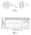
- the source of the electrically induced birefringence can be illustrated by considering the cross-section of the helix in the plane perpendicular to the direction of propagation ( Fig.3 ). Without an applied field, the rotation of the undeflected director traces out a full circle, under an applied field, the directors which lie with their axes perpendicular to the field are tilted out of the plane, reducing their component in the x direction. The directors that lie with their long axis parallel to the field meanwhile are simply rotated about their long axis, resulting in no change to the value of the indicatrix acting on the light for this direction of polarization.
- I I 0 sin 2 2 ⁇ ⁇ ⁇ sin 2 ⁇ ⁇ nd ⁇ ⁇ ⁇
- I / I 0 the fraction of incident intensity transmitted
- ⁇ the angle between the optic axis of the material and the polarizer
- ⁇ the wavelength of the incident light.
- Fig. 5 shows the anticipated frequency doubled response caused by the metronomic action of the optic axis in the bipolar field, going through the optically neutral vertical position twice per cycle at 0 V/ ⁇ m. It also shows a very small predicted response (8% total modulation) due to the small induced birefringence. It is this response the device ought to produce, although Fig.5 is idealised as it takes no account of the material response time.
- the device of the present invention can be used as a fast, endlessly rotatable waveplate for polarization mode dispersion compensation, notably in optical fibre systems.
- the device may function as any desired wave plate, for example as a quarter-wave plate or a half-wave plate in any direction.
- Applications include optical routers and drop muliplexers.
- the device of the present invention is insensitive to input light polarization and, because the pitch may be adjusted, can be optimized for any desired input wavelength.
- An optical router preferably has at least four electrodes, but any desired number may be employed, for example, six, eight, or ten, depending on the number of outputs required.
- the light output carriers may comprise optical fibres for connection to different devices or components.
- the light source may comprise an optical fibre coupled to a light emitter of suitable wavelength range, notably the telecommunications range from about 1530 nm to about 1563 nm.
- the FFO-9-OCB was mixed with the high twisting power chiral dopant BDH1281 (Merck NB-C) in proportions of 2% w/w and 3% for the first and second mixtures respectively.
- the third mixture consisted of 4-heptyl-alkyloxy-4'-cyanobiphenyl (7OCB), whose structure and flexoelectro-optic properties are well known 15 , and 3%(w/w) BDH1281, and was intended as a control mixture.
- Each of these mixtures were heated into the isotropic phase for a period of 24 hours in order to allow complete mixing, and were capillary-filled into the test cells in the isotropic phase.
- the mixtures were each phase characterized using polarizing microscopy and their reflection band in the N* phase measured using a UV-Visible spectrophotometer. This can be used to estimate the pitch length of the material, taking an approximate average refractive index of 1.6, and was found to give pitches of 485 nm, 300 nm, and 410 nm respectively for the mixtures as ordered above.
- test cells were manufactured by Pi Photonics Ltd for development of a homeotropically aligned nematic rotating waveplate. With this purpose, they were designed with 4 electrodes converging on a 50 ⁇ m diameter active area, such that by varying the voltage on all four electrodes, the field in the centre of the active region could be applied in any direction in the plane of the cell, and the optic axis rotated to the desired azimuth.
- the electrode layout of the cell can be seen in Figure 7 .
- the field is applied solely between the two central electrodes, and the probe beam is directed in the narrow (50 ⁇ m) portion of the channel between these, which appears boxed in the figure. This allows maximum confidence in the uniformity of the field.
- the electrodes are deposited gold, 10 ⁇ m thick, and also act as spacers onto which to glue the lid of the cell and define its thickness.
- the cell is spin-coated with a 1% solution in water of PVA which is then evaporated to deposit an alignment layer promoting planar orientation of the nematic director.
- the layer cannot be rubbed however due to the presence of the electrodes, so although the liquid crystal molecules are made to lie flat in the cell, there is no preferential direction for their orientation within the plane of the cell.
- a lid consisting of a 2 mm 2 cleaved section of microscope cover slip 100 ⁇ m thick is placed onto the cell, having been coated with an alignment of unidirectional rubbed PTFE. This is found to provide a more reliable alignment and superior texture than PVA.
- the lid is then fixed to the cell utilising capillary action to draw the UV curing glue over the electrodes without filling the channels, and exposing to set.
- the chiral nematic can itself be capillary filled through the channels to fill the cell, and then the cell sealed with a second application of glue around the edges of the lid.
- a polarizing microscope is then used to verify the presence of the required Grandjean texture when the cell is brought into the chiral nematic range.
- the filled and sealed cell is then placed into a probe station which uses micrometer screws to clamp contacts onto the four electrodes, and to manoeuvre the position of the cell in the probe beam.
- the probe station has connections to an amplified signal generator output which allows pulses of varying shape and width, and amplitude up to 400 Vpp, to be applied across the cell. It is also equipped with a heating element and thermometer allowing the cell to be maintained at a specific temperature.
- the probe beam is a 1550 nm fibre launched DFB laser.
- the cell is placed between crossed polarizers and microscope objective lenses, such that the emerging beam is polarized, focused directly through the relevant portion of the cell, re-collimated through the second orthogonal polarizer and focused into a power meter.
- the output from the power meter can then be viewed alongside the electronic pulse applied to the cell on a digital phosphor oscilloscope. This arrangement can be seen in Figure 8 .
- the output power of the laser is adjusted to give approximately 100 ⁇ W total power transmission to the detector with zero field applied to the cell and the second polarizer uncrossed.
- the power transmission at zero field with the polarizers crossed is also checked and found to be below 5 ⁇ W for all polarizer angles, confirming the lack of optical activity and birefringence in the Grandjean texture for the test wavelength. This is provided that there are no birefringent "oily streak" disclinations in the area of the cell sampled by the beam.
- the induced birefringence then can be inferred from the fraction of light transmitted during the pulse.
- the applied voltage took the form of a bipolar square pulse of 2 ms duration and 5 Hz repetition rate for all measurements, and the response trace used was averaged over 16 pulses.
- the repetition rate was kept deliberately low, as the application of a continuous bipolar square wave at the equivalent frequency resulted in instabilities in the N* texture, the development and movement of birefringent disclinations, which altered the cell's optical response.
- the Grandjean texture remained very stable, and the cell could be left for several hours without any significant change in the shape or size of the response.
- the response is fast ( ⁇ 100 ⁇ s), and is independent of the field direction, although it can be seen from the dip in transmission as the field changes value that the optic axis follows the field as expected from flexoelectro-optic theory, but the transmission is dependent only on the magnitude of the optic axis tilt, not its direction.
- the flexoelectro-optic axis tilt is given by equation 4, where ⁇ is the induced tilt angle, e/K is the flexo-elastic ratio and P is the helical pitch of the material.
- tan ⁇ 2 ⁇ ⁇ P ⁇ e K ⁇ E
- the tan function is approximately linear for the range of tilt angles expected, so the transmission of the system will depend on how the effective refractive indices in the polarization plane of the light change for a given tilt angle, which ultimately rests on the shape of the refractive indicatrix.
- a preliminary analysis of the expected transmission for a given tilt angle was performed using Jones matrix representation of the projection of the refractive indicatrix ellipsoid in the plane of polarisation. This projection was calculated for rotations of the ellipsoid from flexoelectro-optic theory, for estimated infra-red refractive indices and an average pitch length of 500 ⁇ m, the result being shown in Figure 11 .
- Figure 13 shows the dependence of the maximum intensity transmitted through crossed polarisers of the device on the angle of the applied field to the polariser.
- the expected sin 2 (2 ⁇ ) response is observed, in accordance with equations 3 and 4.
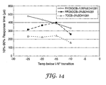
- the response times of the mixtures are shown for application and removal of an applied field at 3 V/ ⁇ at a range of temperatures below the I-N* transition in Figures 14 and 15 respectively.
- the response times can be seen to increase with increasing pitch length, and show a slight increase on cooling for all mixtures, as expected.
- the relaxation times upon removal of a field are generally faster than the response to the application of a field, which is most unusual in liquid crystal effects and to which no explanation can be applied as yet.
- the response times can be seen to be fast-comfortably sub-millisecond, which is encouraging for possible development of a fast response polarization control device for telecommunications wavelengths.
- the flexoelectro-optic effect operates with a short-pitch chiral nematic material aligned in the Grandjean texture, and has the ability to induce a birefringence in the material at telecommunications wavelengths where otherwise the conformation would be optically neutral.
- the response time of this effect is fast ( ⁇ 100 ⁇ s), in line with expectation from the conventional ULH based flexoelectro-optic effect, but the magnitude of the response, especially in 7OCB, is much greater than expected ( ⁇ >2 ⁇ /3).
- a PMD compensator must be able to take the randomly fluctuating state of polarization (SOP) that is output from a long communication fibre due to the temporary birefringence induced in the fibre by vibrations and temperature changes etc, and convert it with minimal loss into the desired polarization state.
- SOP state of polarization
- This is made possible by a series of three rotating waveplates of n/2, n, and n/2 retardance 11 .
- Liquid crystals have been utilised to manufacture such devices previously using simple nematic 5,6,12 and faster electroclinic 13 switching mechanisms, but it is desirable to improve either speed or overall retardance in a reliable cell structure in order to offer the most effective solution. It is thought that the Grandjean flexoelectro-optic mechanism demonstrated here may provide these improvements.
- Three developments are desirable to optimise this novel effect in a commercial device:
- bimesogenic materials used in these mixtures are referred to by their abbreviations, which correspond to the following chemicals: ⁇ -(2',4-difluorobiphenyl-4'-yloxy)- ⁇ -(4-cyanobiphenyl-4'-yloxy)undecane (FFO11OCB); ⁇ -(2',4-difluorobiphenyl-4'-yloxy)- ⁇ -(2',4-difluorobiphenyl-4'-yloxy)nonane (FFO9OFF); ⁇ -(2',4-difluorobiphenyl-4'-yloxy)- ⁇ -(2',4-difluorobiphenyl-4'-yloxy)undecane (FFO11OFF); ⁇ -(2',4-difluorobiphenyl-4'-ester)- ⁇ -(2',4-difluorobiphenyl-4'-ester)nonan
- the cells were constructed as before, with the exception that both the cell and the lid, which consists of a 100 ⁇ m thick cover slip cleaved to fit the cell, were coated with an alignment layer to promote planar alignment of the liquid crystal at the cell surfaces.
- a linearly photopolymerizable photopolymer LPP (Rolic inc)
- Rolic inc linearly photopolymerizable photopolymer
- the lid was fixed to the cell by allowing UV curing glue to wet between the top surfaces of the bulk electrodes and lid via capillary action before curing.
- the cell gap was then measured using a Fabry-Perot interference technique.
- the cell could then be filled with a chiral nematic mixture, the desired Grandjean texture obtained and stabilized by UV exposure to cross-link the reactive mesogen.
- the cells were placed in the same experimental apparatus as before, and subjected to continuous AC square wave voltages.
- the degree to which the response drops at these transitions is dependent on the extent to which dielectric helix unwinding produces a "baseline" birefringence which is constant over the field transition points, as discussed earlier.
- This baseline reveals itself in the high frequency (>2 kHz) traces, in which the flexoelectro-optic movement of the optic axis is too slow to follow the field oscillations. In this situation, the optic axis oscillates only slightly about the helix axis, and the observed birefringence is roughly constant over the a.c. waveform.
- Fig 17 The differing effects of the flexoelectro-optic and dielectric deformation on the chiral nematic helix structure resulting from the continuous square wave are illustrated in Fig 17 .
- This also shows how both deformations result in a similar birefringence, requiring the alteration of driving frequency to separate their effects.
- the effect of the deformation is viewed along (upper figure) and perpendicular (lower figure) to the helical axis to illustrate the source of the resulting birefringence. Note in the flexoelectric example the differing electric field direction for the two views, necessary for illustrative purposes.
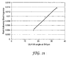
- the flexoelectro-optic tilt angles for each material were measured at 6.8 V/ ⁇ m in the ULH textured cells. If the field following (flexoelectro-optic) component of the induced birefringence, which is simply the amplitude of the modulation in the "a" trace for each of Figures 18 to 20 , is plotted against the flexoelectro-optic tilt angle in the ULH ( Figure 21 ), a good correlation is found, supporting the conclusion that the same flexoelectro-optic deformation is responsible for this portion of the effect. The trend shown in this figure can be seen to tend to zero birefringence for tilt angles of approximately 8 degrees or less.
- Table I shows the averaged 10-90% and 90-10% response times observed in both the Grandjean textured in-plane field cell, and the ULH textured flexoelectro-optic cells. All times are measured at T c -10°, for a switch from 0 V to 4 V/ ⁇ m and back in the Grandjean case and from -4 to +4 V/ ⁇ m and back in the ULH case.
Landscapes
- Physics & Mathematics (AREA)
- Nonlinear Science (AREA)
- General Physics & Mathematics (AREA)
- Optics & Photonics (AREA)
- Chemical & Material Sciences (AREA)
- Crystallography & Structural Chemistry (AREA)
- Liquid Crystal (AREA)
- Liquid Crystal Substances (AREA)
Claims (28)
- Dispositif avec état de polarisation contrôlé de lumière de sortie, le dispositif comprenant :une cellule et une source de lumière agencées pour diriger une lumière polarisée à travers la cellule le long d'une direction de propagation de lumière ;ladite cellule comprenant des première et seconde parois de cellule renfermant une couche d'un matériau cristallin liquide nématique chiral dont l'axe hélicoïdal est orienté de façon sensiblement parallèle à ladite direction de propagation de lumière à travers la cellule en l'absence d'un champ électrique ;la cellule comprenant en outre des électrodes agencées pour appliquer un champ électrique sensiblement perpendiculaire à l'orientation dudit axe hélicoïdal en l'absence d'un champ électrique ;caractérisé en ce que le matériau cristallin liquide possède un pas hélicoïdal sensiblement plus court que la longueur d'onde de la lumière de la source de lumière.
- Dispositif selon la revendication 1, dans lequel le matériau cristallin liquide possède un pas hélicoïdal inférieur à 1 µm.
- Dispositif selon la revendication 2, dans lequel le pas hélicoïdal est dans la plage de 200 à 800 nm.
- Dispositif selon l'une quelconque des revendications précédentes, dans lequel lesdites électrodes comprennent au moins quatre électrodes agencées autour d'une région de la couche de cristal liquide, chaque électrode étant adressable sélectivement pour appliquer un champ électrique sur ladite région, moyennant quoi ledit champ électrique peut être appliqué dans l'une quelconque parmi une pluralité de directions sélectionnables sensiblement parallèles aux surfaces intérieures des parois de cellules.
- Dispositif selon la revendication 1, dans lequel ladite source de lumière est agencée pour diriger la lumière sur ladite première paroi de cellule dans une direction sensiblement normale par rapport aux surfaces intérieures des parois de cellule.
- Dispositif selon la revendication 1, dans lequel ladite source de lumière est agencée pour diriger la lumière sur un espace entre le bord des parois de cellule, de façon sensiblement parallèle aux surfaces intérieures des parois de cellule.
- Dispositif selon l'une quelconque des revendications précédentes, dans lequel ladite source de lumière comprend une fibre optique couplée à un émetteur de lumière.
- Dispositif selon la revendication 7, dans lequel l'émetteur de lumière est adapté pour émettre une lumière possédant des longueurs d'onde dans la plage de 200 à 2000 nm.
- Dispositif selon la revendication 8, dans lequel l'émetteur de lumière est adapté pour émettre une lumière possédant des longueurs d'onde dans la plage de 1400 à 1600 nm.
- Dispositif selon la revendication 9, dans lequel l'émetteur de lumière est adapté pour émettre une lumière possédant des longueurs d'onde dans la plage de télécommunication d'environ 1530 à 1563 nm.
- Dispositif selon l'une quelconque des revendications précédentes, dans lequel ladite source de lumière comprend un émetteur de micro-ondes.
- Dispositif selon l'une quelconque des revendications précédentes, comprenant en outre un réseau polymère à l'intérieur du matériau cristallin liquide, pour stabiliser une texture du matériau cristallin liquide.
- Dispositif selon la revendication 12, dans lequel ledit réseau polymère comprend de 3 à 6 % en poids de la couche de cristal liquide et un polymère.
- Dispositif selon la revendication 12 ou la revendication 13, dans lequel ledit réseau polymère comprend un matériau mésogène polymérisé.
- Dispositif selon l'une quelconque des revendications 12 à 14, dans lequel ledit polymère est réticulé.
- Dispositif selon la revendication 1, comprenant en outre :une seconde cellule comprenant des première et seconde parois de cellule renfermant une couche d'un matériau cristallin liquide nématique chiral ayant son axe hélicoïdal sensiblement parallèle à la direction de propagation de lumière à travers la seconde cellule en l'absence d'un champ électrique ;la seconde cellule possédant des électrodes agencées pour appliquer un champ électrique sensiblement perpendiculaire à l'orientation dudit axe hélicoïdal en l'absence d'un champ électrique ;dans lequel les cellules sont agencées l'une pardessus l'autre avec toutes les parois de cellule sensiblement parallèles les unes aux autres de sorte que la lumière se propageant à travers la première cellule se propagera par la suite à travers la seconde cellule.
- Procédé de commande du dispositif selon la revendication 16, comprenant l'étape consistant à appliquer des formes d'onde sensiblement identiques sur les électrodes desdites cellules, les formes d'onde étant déphasées d'un quart de cycle les unes par rapport aux autres, et la forme des formes d'onde étant telle que la somme de la biréfringence provoquée dans chacune des cellules est sensiblement constante.
- Procédé selon la revendication 17, dans lequel les axes optiques des couches de matériau cristallin liquide desdites cellules sont tournés dans la même direction ou à l'encontre les uns des autres.
- Utilisation d'une cellule dans un dispositif selon la revendication 1 pour contrôler l'état de polarisation de la lumière visible polarisée transmise par la cellule, la cellule comprenant des première et seconde parois de cellule renfermant une couche d'un matériau cristallin liquide nématique chiral dont l'axe hélicoïdal est orienté de façon sensiblement parallèle à la direction de propagation de lumière à travers la cellule en l'absence d'un champ électrique, et des électrodes agencées pour appliquer un champ électrique sensiblement perpendiculaire à l'orientation dudit axe hélicoïdal en l'absence d'un champ électrique ; caractérisée en ce que le pas hélicoïdal du matériau cristallin liquide est sensiblement plus court que la longueur d'onde de la lumière visible.
- Routeur optique comprenant :a) une cellule comprenant des première et seconde parois de cellule renfermant une couche d'un matériau cristallin liquide nématique chiral d'anisotropie diélectrique positive ou négative dont l'axe hélicoïdal est orienté de façon sensiblement normale par rapport aux surfaces intérieures des parois de cellule et parallèle à la direction de propagation de lumière à travers la cellule en l'absence d'un champ électrique, et une pluralité d'électrodes agencées autour d'une région d'entrée de lumière de la couche de cristal liquide, chaque électrode étant adressable sélectivement pour appliquer un champ électrique sur ladite région d'entrée de lumière, moyennant quoi ledit champ électrique peut être appliqué dans l'une quelconque parmi une pluralité de directions sélectionnables sensiblement parallèles aux surfaces intérieures des parois de cellule, afin de contrôler l'état et/ou la direction de polarisation de la lumière transmise ;b) une source de lumière agencée pour diriger la lumière polarisée à travers ladite région d'entrée de lumière par l'intermédiaire de ladite première paroi de cellule le long de ladite direction de propagation de lumière ; etc) une pluralité de porteurs de sortie de lumière dont chacun est agencé et adapté pour recevoir de la lumière provenant de ladite région d'entrée de lumière par l'intermédiaire de ladite seconde paroi de cellule lorsque ladite lumière est d'un état spécifié et/ou d'une direction de polarisation spécifiée, ledit état spécifié et/ou ladite direction de polarisation spécifiée étant différents pour chaque porteur de sortie de lumière ; dans lequeld) le pas hélicoïdal du matériau cristallin liquide est sensiblement plus court que la longueur d'onde de la lumière provenant de la source de lumière.
- Routeur optique comprenant :a) une cellule comprenant des première et seconde parois de cellule renfermant une couche d'un matériau cristallin liquide nématique chiral d'anisotropie diélectrique positive ou négative dont l'axe hélicoïdal est orienté de façon sensiblement parallèle aux surfaces intérieures des parois de cellule et parallèle à la direction de propagation de lumière à travers la cellule, en l'absence d'un champ électrique, et une pluralité d'électrodes agencées autour d'une région d'entrée de lumière de la couche de cristal liquide, chaque électrode étant adressable sélectivement pour appliquer un champ électrique sur ladite région d'entrée de lumière, moyennant quoi ledit champ électrique peut être appliqué dans l'une quelconque parmi une pluralité de directions sélectionnables sensiblement perpendiculaires audit axe hélicoïdal, afin de contrôler l'état et/ou la direction de polarisation de la lumière transmise ;b) une source de lumière agencée pour diriger la lumière polarisée à travers ladite région d'entrée de lumière dans l'espace entre le côté des parois de cellule le long de ladite direction de propagation de lumière ; etc) une pluralité de porteurs de sortie de lumière dont chacun est agencé et adapté pour recevoir de la lumière provenant de ladite région d'entrée de lumière par l'intermédiaire dudit espace de cellule lorsque ladite lumière est d'un état spécifié et/ou d'une direction de polarisation spécifiée, ledit état spécifié et/ou ladite direction de polarisation spécifiée étant différents pour chaque porteur de sortie de lumière ; dans lequeld) le pas hélicoïdal du matériau cristallin liquide est sensiblement plus court que la longueur d'onde de la lumière provenant de la source de lumière.
- Routeur optique selon la revendication 20 ou la revendication 21, dans lequel le pas hélicoïdal représente 10 à 50 % de la longueur d'onde de la lumière provenant de la source d'entrée de lumière.
- Routeur optique selon l'une quelconque des revendications 20 à 22, dans lequel la lumière provenant de la source d'entrée de lumière possède une longueur d'onde dans la plage de télécommunication d'environ 1530 à 1563 nm.
- Dispositif ou routeur optique selon l'une quelconque des revendications précédentes, dans lequel le matériau cristallin liquide est ou contient un matériau nématique chiral bimésogène d'anisotropie diélectrique positive.
- Dispositif ou routeur optique selon la revendication 24, dans lequel ledit bimésogène est un α-(2',4-difluorobiphényl-4'-yloxy)-ω-(4-cyanobiphényl-4'-yloxy)nonane.
- Procédé de contrôle ou modification de l'état de polarisation d'une lumière se propageant à travers une couche d'un cristal liquide nématique chiral d'anisotropie diélectrique positive possédant un axe hélicoïdal et étant coincée entre des parois de cellule translucides sensiblement planes, la direction de propagation de lumière étant sensiblement parallèle à l'orientation dudit axe hélicoïdal en l'absence d'un champ électrique, le procédé comprenant l'étape consistant à appliquer un champ électrique sensiblement perpendiculaire à l'axe hélicoïdal afin de déformer la structure hélicoïdale du cristal liquide par couplage flexoélectrique des molécules du matériau cristallin liquide au champ appliqué, changeant ainsi la biréfringence volumique du cristal liquide ;
dans lequel la lumière possède une longueur d'onde dans la plage d'infrarouge proche, de micro-onde ou visible, caractérisé en ce que le pas de la structure hélicoïdale est sensiblement inférieur à ladite longueur d'onde, de sorte que la biréfringence volumique du cristal liquide soit sensiblement nulle en l'absence d'un champ électrique. - Procédé selon la revendication 26, dans lequel l'axe hélicoïdal est sensiblement normal par rapport au plan des parois de cellule.
- Dispositif d'affichage comprenant un pixel agencé entre des polarisateurs croisés afin d'effectuer un contrôle d'intensité à partir du procédé de contrôle de polarisation selon la revendication 26.
Applications Claiming Priority (2)
| Application Number | Priority Date | Filing Date | Title |
|---|---|---|---|
| GBGB0414882.1A GB0414882D0 (en) | 2004-07-02 | 2004-07-02 | Liquid crystal device |
| PCT/GB2005/002630 WO2006003441A1 (fr) | 2004-07-02 | 2005-07-04 | Dispositif flexoelectro-optique a cristaux liquides |
Publications (2)
| Publication Number | Publication Date |
|---|---|
| EP1766461A1 EP1766461A1 (fr) | 2007-03-28 |
| EP1766461B1 true EP1766461B1 (fr) | 2008-09-17 |
Family
ID=32843483
Family Applications (1)
| Application Number | Title | Priority Date | Filing Date |
|---|---|---|---|
| EP05757410A Expired - Lifetime EP1766461B1 (fr) | 2004-07-02 | 2005-07-04 | Dispositif flexoelectro-optique a cristaux liquides |
Country Status (9)
| Country | Link |
|---|---|
| US (1) | US8330931B2 (fr) |
| EP (1) | EP1766461B1 (fr) |
| JP (1) | JP5190262B2 (fr) |
| KR (1) | KR101211869B1 (fr) |
| CN (1) | CN100489598C (fr) |
| AT (1) | ATE408855T1 (fr) |
| DE (1) | DE602005009831D1 (fr) |
| GB (1) | GB0414882D0 (fr) |
| WO (1) | WO2006003441A1 (fr) |
Cited By (1)
| Publication number | Priority date | Publication date | Assignee | Title |
|---|---|---|---|---|
| WO2010139995A1 (fr) | 2009-06-02 | 2010-12-09 | Cambridge Enterprise Limited | Dispositif à cristaux liquides comprenant un matériau à cristaux liquides nématiques chiraux ayant un agencement hélicoïdal |
Families Citing this family (17)
| Publication number | Priority date | Publication date | Assignee | Title |
|---|---|---|---|---|
| GB0820872D0 (en) | 2008-11-14 | 2008-12-24 | Cambridge Entpr Ltd | Optical beam steering |
| GB0906377D0 (en) * | 2009-04-14 | 2009-05-20 | Cambridge Entpr Ltd | Phase modulation devices for optical applications |
| KR101688593B1 (ko) * | 2009-12-28 | 2016-12-23 | 엘지디스플레이 주식회사 | 횡전계 모드 반사투과형 액정표시장치 |
| TWI510850B (zh) * | 2010-05-18 | 2015-12-01 | Univ Hong Kong Science & Techn | A liquid crystal display element having a fast response and a continuous gray scale |
| KR101333614B1 (ko) * | 2010-06-25 | 2013-11-27 | 엘지디스플레이 주식회사 | 액정표시장치 |
| TW201217860A (en) * | 2010-10-25 | 2012-05-01 | Ind Tech Res Inst | Cholesteric liquid crystal device |
| GB201113324D0 (en) | 2011-08-02 | 2011-09-14 | Cambridge Entpr Ltd | Laser system and method for operating laser system |
| EP2855631B1 (fr) * | 2012-05-25 | 2017-09-20 | Merck Patent GmbH | Milieux mésogènes et afficheur à cristaux liquides |
| GB201304926D0 (en) * | 2013-03-18 | 2013-05-01 | Isis Innovation | Liquid crystal state switching |
| JP2018501514A (ja) * | 2014-12-19 | 2018-01-18 | メルク パテント ゲゼルシャフト ミット ベシュレンクテル ハフツングMerck Patent Gesellschaft mit beschraenkter Haftung | 光変調素子 |
| CN108700776B (zh) * | 2015-12-25 | 2021-10-26 | 日产化学工业株式会社 | 液晶表示元件、液晶光学元件及液晶结构体稳定化膜用组合物 |
| CN105652550B (zh) * | 2016-04-07 | 2019-03-01 | 京东方科技集团股份有限公司 | 液晶混合物、光截止部件及其制备方法和显示装置 |
| CN110741290B (zh) * | 2017-07-12 | 2022-03-11 | 富士胶片株式会社 | 液晶组合物、反射层的制造方法、反射层、固化物及光学各向异性体 |
| US10619099B2 (en) * | 2017-08-25 | 2020-04-14 | Ppg Industries Ohio, Inc. | Dielectric devices and methods of fabrication |
| KR102182135B1 (ko) | 2019-03-27 | 2020-11-23 | 전북대학교산학협력단 | 바이메조게닉 액정 도핑을 통한 네마틱 변전효과를 이용한 휨 및 압력 감지 센서 |
| US12382733B2 (en) * | 2020-08-31 | 2025-08-05 | Massachusetts Institute Of Technology | Flexo-electric broadband photo-detectors and electrical energy generators |
| US12265505B2 (en) | 2023-01-27 | 2025-04-01 | The Toronto-Dominion Bank | Systems and methods for automated reporting |
Family Cites Families (9)
| Publication number | Priority date | Publication date | Assignee | Title |
|---|---|---|---|---|
| US4917475A (en) * | 1987-03-06 | 1990-04-17 | At&T Bell Laboratories | Flexoelectric liquid crystal device |
| GB2329481A (en) * | 1997-09-19 | 1999-03-24 | Sharp Kk | Supertwist nematic liquid crystal |
| KR100320102B1 (ko) | 1998-11-21 | 2002-04-22 | 김원대 | 수직배향된나선변형강유전성액정표시장치 |
| GB2356629B (en) * | 1999-10-04 | 2004-09-22 | Merck Patent Gmbh | Bimesogenic Compounds and Flexoelectric Devices |
| US6766082B2 (en) * | 2000-10-18 | 2004-07-20 | Nippon Telegraph And Telephone Corporation | Waveguide-type optical device and manufacturing method therefor |
| US6735009B2 (en) * | 2002-07-16 | 2004-05-11 | Motorola, Inc. | Electroptic device |
| US6937308B2 (en) * | 2002-07-26 | 2005-08-30 | Eastman Kodak Company | In-plane switching liquid crystal display with compensation film |
| GB0220381D0 (en) | 2002-09-02 | 2002-10-09 | Pi Photonics Ltd | Liquid crystal device construction |
| ATE314446T1 (de) * | 2002-10-08 | 2006-01-15 | Merck Patent Gmbh | Flüssigkristallines medium und flüssigkristallanzeige |
-
2004
- 2004-07-02 GB GBGB0414882.1A patent/GB0414882D0/en not_active Ceased
-
2005
- 2005-07-04 WO PCT/GB2005/002630 patent/WO2006003441A1/fr not_active Ceased
- 2005-07-04 DE DE602005009831T patent/DE602005009831D1/de not_active Expired - Lifetime
- 2005-07-04 EP EP05757410A patent/EP1766461B1/fr not_active Expired - Lifetime
- 2005-07-04 JP JP2007518712A patent/JP5190262B2/ja not_active Expired - Fee Related
- 2005-07-04 CN CNB200580029632XA patent/CN100489598C/zh not_active Expired - Fee Related
- 2005-07-04 KR KR1020077002754A patent/KR101211869B1/ko not_active Expired - Fee Related
- 2005-07-04 US US11/631,130 patent/US8330931B2/en not_active Expired - Fee Related
- 2005-07-04 AT AT05757410T patent/ATE408855T1/de not_active IP Right Cessation
Cited By (1)
| Publication number | Priority date | Publication date | Assignee | Title |
|---|---|---|---|---|
| WO2010139995A1 (fr) | 2009-06-02 | 2010-12-09 | Cambridge Enterprise Limited | Dispositif à cristaux liquides comprenant un matériau à cristaux liquides nématiques chiraux ayant un agencement hélicoïdal |
Also Published As
| Publication number | Publication date |
|---|---|
| CN100489598C (zh) | 2009-05-20 |
| JP5190262B2 (ja) | 2013-04-24 |
| CN101023391A (zh) | 2007-08-22 |
| US8330931B2 (en) | 2012-12-11 |
| ATE408855T1 (de) | 2008-10-15 |
| WO2006003441A1 (fr) | 2006-01-12 |
| KR20070059057A (ko) | 2007-06-11 |
| EP1766461A1 (fr) | 2007-03-28 |
| US20090167970A1 (en) | 2009-07-02 |
| KR101211869B1 (ko) | 2012-12-12 |
| GB0414882D0 (en) | 2004-08-04 |
| DE602005009831D1 (de) | 2008-10-30 |
| JP2008504586A (ja) | 2008-02-14 |
Similar Documents
| Publication | Publication Date | Title |
|---|---|---|
| US8330931B2 (en) | Flexoelectro-optic liquid crystal device | |
| KR100251514B1 (ko) | 콜레스테롤성 액정 장치 | |
| Škarabot et al. | Birefringence and tilt angle in the antiferroelectric, ferroelectric, and intermediate phases of chiral smectic liquid crystals | |
| Presnyakov et al. | Electrically tunable polymer stabilized liquid-crystal lens | |
| Broughton et al. | Optimized flexoelectric response in a chiral liquid-crystal phase device | |
| US7652731B2 (en) | Polymer enhanced cholesteric electro-optical devices | |
| JP2582723B2 (ja) | ねじれ強誘電性液晶光学装置及びグレースケール変調方法 | |
| Gupta et al. | Ferroelectric liquid crystals: futuristic mesogens for photonic applications | |
| Liang et al. | Dual-frequency addressed variable optical attenuator with submillisecond response time | |
| RU2366989C2 (ru) | Способ управления поляризацией света и быстродействующий управляемый оптический элемент с применением холестерического жидкого кристалла (варианты) | |
| Yoon et al. | Homogeneous and homeotropic alignment of bent-core uniaxial and biaxial nematic liquid crystals | |
| Guo et al. | Voltage sensor with wide frequency range using deformed helix ferroelectric liquid crystal | |
| Ali et al. | On‐Demand Polarization Controllable Liquid Crystal Laser | |
| US9400412B2 (en) | Nanosecond liquid crystalline optical modulator | |
| Xu et al. | 11.4 L: Late‐news paper: very high pretilt alignment and its application in Pi‐cell LCDS | |
| D'ALESSANDRO et al. | Realisation and characterisation of a ferroelectric liquid crystal bistable optical switch | |
| US7604850B2 (en) | Biaxial liquid crystal electro-optic devices | |
| Gros et al. | Ferroelectric liquid crystal optical waveguide switches using the double-refraction effect | |
| Scalia et al. | Integrated electro-optic switch based on a ferroelectric liquid crystal waveguide | |
| Semenova et al. | Liquid crystal based optical switches | |
| Chigrinov | Liquid crystal devices for photonics applications | |
| Broughton et al. | Liquid crystal based continuous phase retarder: from optically neutral to a quarter waveplate in 200 microseconds | |
| Amosova et al. | Ways of increasing the response rate of electrically controlled optical devices based on nematic liquid crystals | |
| Nose et al. | Application of a liquid crystal microlens to an optical fiber switch | |
| Wang et al. | Transmissive flexoelectro-optic liquid crystal optical phase modulator with 2π modulation |
Legal Events
| Date | Code | Title | Description |
|---|---|---|---|
| PUAI | Public reference made under article 153(3) epc to a published international application that has entered the european phase |
Free format text: ORIGINAL CODE: 0009012 |
|
| 17P | Request for examination filed |
Effective date: 20070126 |
|
| AK | Designated contracting states |
Kind code of ref document: A1 Designated state(s): AT BE BG CH CY CZ DE DK EE ES FI FR GB GR HU IE IS IT LI LT LU LV MC NL PL PT RO SE SI SK TR |
|
| 17Q | First examination report despatched |
Effective date: 20070814 |
|
| DAX | Request for extension of the european patent (deleted) | ||
| GRAP | Despatch of communication of intention to grant a patent |
Free format text: ORIGINAL CODE: EPIDOSNIGR1 |
|
| GRAS | Grant fee paid |
Free format text: ORIGINAL CODE: EPIDOSNIGR3 |
|
| GRAA | (expected) grant |
Free format text: ORIGINAL CODE: 0009210 |
|
| AK | Designated contracting states |
Kind code of ref document: B1 Designated state(s): AT BE BG CH CY CZ DE DK EE ES FI FR GB GR HU IE IS IT LI LT LU LV MC NL PL PT RO SE SI SK TR |
|
| REG | Reference to a national code |
Ref country code: GB Ref legal event code: FG4D |
|
| REG | Reference to a national code |
Ref country code: CH Ref legal event code: EP |
|
| REG | Reference to a national code |
Ref country code: IE Ref legal event code: FG4D |
|
| REF | Corresponds to: |
Ref document number: 602005009831 Country of ref document: DE Date of ref document: 20081030 Kind code of ref document: P |
|
| PG25 | Lapsed in a contracting state [announced via postgrant information from national office to epo] |
Ref country code: LT Free format text: LAPSE BECAUSE OF FAILURE TO SUBMIT A TRANSLATION OF THE DESCRIPTION OR TO PAY THE FEE WITHIN THE PRESCRIBED TIME-LIMIT Effective date: 20080917 |
|
| PG25 | Lapsed in a contracting state [announced via postgrant information from national office to epo] |
Ref country code: LV Free format text: LAPSE BECAUSE OF FAILURE TO SUBMIT A TRANSLATION OF THE DESCRIPTION OR TO PAY THE FEE WITHIN THE PRESCRIBED TIME-LIMIT Effective date: 20080917 Ref country code: SI Free format text: LAPSE BECAUSE OF FAILURE TO SUBMIT A TRANSLATION OF THE DESCRIPTION OR TO PAY THE FEE WITHIN THE PRESCRIBED TIME-LIMIT Effective date: 20080917 Ref country code: AT Free format text: LAPSE BECAUSE OF FAILURE TO SUBMIT A TRANSLATION OF THE DESCRIPTION OR TO PAY THE FEE WITHIN THE PRESCRIBED TIME-LIMIT Effective date: 20080917 Ref country code: FI Free format text: LAPSE BECAUSE OF FAILURE TO SUBMIT A TRANSLATION OF THE DESCRIPTION OR TO PAY THE FEE WITHIN THE PRESCRIBED TIME-LIMIT Effective date: 20080917 |
|
| PG25 | Lapsed in a contracting state [announced via postgrant information from national office to epo] |
Ref country code: BE Free format text: LAPSE BECAUSE OF FAILURE TO SUBMIT A TRANSLATION OF THE DESCRIPTION OR TO PAY THE FEE WITHIN THE PRESCRIBED TIME-LIMIT Effective date: 20080917 |
|
| PG25 | Lapsed in a contracting state [announced via postgrant information from national office to epo] |
Ref country code: ES Free format text: LAPSE BECAUSE OF FAILURE TO SUBMIT A TRANSLATION OF THE DESCRIPTION OR TO PAY THE FEE WITHIN THE PRESCRIBED TIME-LIMIT Effective date: 20081228 Ref country code: BG Free format text: LAPSE BECAUSE OF FAILURE TO SUBMIT A TRANSLATION OF THE DESCRIPTION OR TO PAY THE FEE WITHIN THE PRESCRIBED TIME-LIMIT Effective date: 20081217 |
|
| PG25 | Lapsed in a contracting state [announced via postgrant information from national office to epo] |
Ref country code: PT Free format text: LAPSE BECAUSE OF FAILURE TO SUBMIT A TRANSLATION OF THE DESCRIPTION OR TO PAY THE FEE WITHIN THE PRESCRIBED TIME-LIMIT Effective date: 20090217 Ref country code: IS Free format text: LAPSE BECAUSE OF FAILURE TO SUBMIT A TRANSLATION OF THE DESCRIPTION OR TO PAY THE FEE WITHIN THE PRESCRIBED TIME-LIMIT Effective date: 20090117 Ref country code: RO Free format text: LAPSE BECAUSE OF FAILURE TO SUBMIT A TRANSLATION OF THE DESCRIPTION OR TO PAY THE FEE WITHIN THE PRESCRIBED TIME-LIMIT Effective date: 20080917 Ref country code: CZ Free format text: LAPSE BECAUSE OF FAILURE TO SUBMIT A TRANSLATION OF THE DESCRIPTION OR TO PAY THE FEE WITHIN THE PRESCRIBED TIME-LIMIT Effective date: 20080917 Ref country code: SK Free format text: LAPSE BECAUSE OF FAILURE TO SUBMIT A TRANSLATION OF THE DESCRIPTION OR TO PAY THE FEE WITHIN THE PRESCRIBED TIME-LIMIT Effective date: 20080917 |
|
| PLBE | No opposition filed within time limit |
Free format text: ORIGINAL CODE: 0009261 |
|
| STAA | Information on the status of an ep patent application or granted ep patent |
Free format text: STATUS: NO OPPOSITION FILED WITHIN TIME LIMIT |
|
| PG25 | Lapsed in a contracting state [announced via postgrant information from national office to epo] |
Ref country code: EE Free format text: LAPSE BECAUSE OF FAILURE TO SUBMIT A TRANSLATION OF THE DESCRIPTION OR TO PAY THE FEE WITHIN THE PRESCRIBED TIME-LIMIT Effective date: 20080917 Ref country code: DK Free format text: LAPSE BECAUSE OF FAILURE TO SUBMIT A TRANSLATION OF THE DESCRIPTION OR TO PAY THE FEE WITHIN THE PRESCRIBED TIME-LIMIT Effective date: 20080917 |
|
| 26N | No opposition filed |
Effective date: 20090618 |
|
| PG25 | Lapsed in a contracting state [announced via postgrant information from national office to epo] |
Ref country code: IT Free format text: LAPSE BECAUSE OF FAILURE TO SUBMIT A TRANSLATION OF THE DESCRIPTION OR TO PAY THE FEE WITHIN THE PRESCRIBED TIME-LIMIT Effective date: 20080917 |
|
| PG25 | Lapsed in a contracting state [announced via postgrant information from national office to epo] |
Ref country code: SE Free format text: LAPSE BECAUSE OF FAILURE TO SUBMIT A TRANSLATION OF THE DESCRIPTION OR TO PAY THE FEE WITHIN THE PRESCRIBED TIME-LIMIT Effective date: 20081217 |
|
| PG25 | Lapsed in a contracting state [announced via postgrant information from national office to epo] |
Ref country code: MC Free format text: LAPSE BECAUSE OF NON-PAYMENT OF DUE FEES Effective date: 20090731 |
|
| REG | Reference to a national code |
Ref country code: CH Ref legal event code: PL |
|
| REG | Reference to a national code |
Ref country code: IE Ref legal event code: MM4A |
|
| PG25 | Lapsed in a contracting state [announced via postgrant information from national office to epo] |
Ref country code: CH Free format text: LAPSE BECAUSE OF NON-PAYMENT OF DUE FEES Effective date: 20090731 Ref country code: LI Free format text: LAPSE BECAUSE OF NON-PAYMENT OF DUE FEES Effective date: 20090731 |
|
| PG25 | Lapsed in a contracting state [announced via postgrant information from national office to epo] |
Ref country code: PL Free format text: LAPSE BECAUSE OF FAILURE TO SUBMIT A TRANSLATION OF THE DESCRIPTION OR TO PAY THE FEE WITHIN THE PRESCRIBED TIME-LIMIT Effective date: 20080917 |
|
| PG25 | Lapsed in a contracting state [announced via postgrant information from national office to epo] |
Ref country code: IE Free format text: LAPSE BECAUSE OF NON-PAYMENT OF DUE FEES Effective date: 20090704 |
|
| PG25 | Lapsed in a contracting state [announced via postgrant information from national office to epo] |
Ref country code: GR Free format text: LAPSE BECAUSE OF FAILURE TO SUBMIT A TRANSLATION OF THE DESCRIPTION OR TO PAY THE FEE WITHIN THE PRESCRIBED TIME-LIMIT Effective date: 20081218 |
|
| PG25 | Lapsed in a contracting state [announced via postgrant information from national office to epo] |
Ref country code: LU Free format text: LAPSE BECAUSE OF NON-PAYMENT OF DUE FEES Effective date: 20090704 |
|
| PG25 | Lapsed in a contracting state [announced via postgrant information from national office to epo] |
Ref country code: HU Free format text: LAPSE BECAUSE OF FAILURE TO SUBMIT A TRANSLATION OF THE DESCRIPTION OR TO PAY THE FEE WITHIN THE PRESCRIBED TIME-LIMIT Effective date: 20090318 |
|
| PG25 | Lapsed in a contracting state [announced via postgrant information from national office to epo] |
Ref country code: TR Free format text: LAPSE BECAUSE OF FAILURE TO SUBMIT A TRANSLATION OF THE DESCRIPTION OR TO PAY THE FEE WITHIN THE PRESCRIBED TIME-LIMIT Effective date: 20080917 |
|
| PG25 | Lapsed in a contracting state [announced via postgrant information from national office to epo] |
Ref country code: CY Free format text: LAPSE BECAUSE OF FAILURE TO SUBMIT A TRANSLATION OF THE DESCRIPTION OR TO PAY THE FEE WITHIN THE PRESCRIBED TIME-LIMIT Effective date: 20080917 |
|
| PGFP | Annual fee paid to national office [announced via postgrant information from national office to epo] |
Ref country code: GB Payment date: 20120719 Year of fee payment: 8 |
|
| PGFP | Annual fee paid to national office [announced via postgrant information from national office to epo] |
Ref country code: FR Payment date: 20120820 Year of fee payment: 8 Ref country code: DE Payment date: 20120720 Year of fee payment: 8 |
|
| PGFP | Annual fee paid to national office [announced via postgrant information from national office to epo] |
Ref country code: NL Payment date: 20120730 Year of fee payment: 8 |
|
| REG | Reference to a national code |
Ref country code: NL Ref legal event code: V1 Effective date: 20140201 |
|
| GBPC | Gb: european patent ceased through non-payment of renewal fee |
Effective date: 20130704 |
|
| REG | Reference to a national code |
Ref country code: DE Ref legal event code: R119 Ref document number: 602005009831 Country of ref document: DE Effective date: 20140201 |
|
| REG | Reference to a national code |
Ref country code: FR Ref legal event code: ST Effective date: 20140331 |
|
| PG25 | Lapsed in a contracting state [announced via postgrant information from national office to epo] |
Ref country code: NL Free format text: LAPSE BECAUSE OF NON-PAYMENT OF DUE FEES Effective date: 20140201 Ref country code: GB Free format text: LAPSE BECAUSE OF NON-PAYMENT OF DUE FEES Effective date: 20130704 Ref country code: DE Free format text: LAPSE BECAUSE OF NON-PAYMENT OF DUE FEES Effective date: 20140201 |
|
| PG25 | Lapsed in a contracting state [announced via postgrant information from national office to epo] |
Ref country code: FR Free format text: LAPSE BECAUSE OF NON-PAYMENT OF DUE FEES Effective date: 20130731 |