EP1766477B1 - Procédé et appareil pour le séchage des plaques d'impression flexographiques - Google Patents
Procédé et appareil pour le séchage des plaques d'impression flexographiques Download PDFInfo
- Publication number
- EP1766477B1 EP1766477B1 EP05752681A EP05752681A EP1766477B1 EP 1766477 B1 EP1766477 B1 EP 1766477B1 EP 05752681 A EP05752681 A EP 05752681A EP 05752681 A EP05752681 A EP 05752681A EP 1766477 B1 EP1766477 B1 EP 1766477B1
- Authority
- EP
- European Patent Office
- Prior art keywords
- plates
- lamps
- air
- flow
- visible light
- Prior art date
- Legal status (The legal status is an assumption and is not a legal conclusion. Google has not performed a legal analysis and makes no representation as to the accuracy of the status listed.)
- Expired - Lifetime
Links
Images


Classifications
-
- G—PHYSICS
- G03—PHOTOGRAPHY; CINEMATOGRAPHY; ANALOGOUS TECHNIQUES USING WAVES OTHER THAN OPTICAL WAVES; ELECTROGRAPHY; HOLOGRAPHY
- G03F—PHOTOMECHANICAL PRODUCTION OF TEXTURED OR PATTERNED SURFACES, e.g. FOR PRINTING, FOR PROCESSING OF SEMICONDUCTOR DEVICES; MATERIALS THEREFOR; ORIGINALS THEREFOR; APPARATUS SPECIALLY ADAPTED THEREFOR
- G03F7/00—Photomechanical, e.g. photolithographic, production of textured or patterned surfaces, e.g. printing surfaces; Materials therefor, e.g. comprising photoresists; Apparatus specially adapted therefor
- G03F7/26—Processing photosensitive materials; Apparatus therefor
- G03F7/40—Treatment after imagewise removal, e.g. baking
-
- B—PERFORMING OPERATIONS; TRANSPORTING
- B41—PRINTING; LINING MACHINES; TYPEWRITERS; STAMPS
- B41C—PROCESSES FOR THE MANUFACTURE OR REPRODUCTION OF PRINTING SURFACES
- B41C1/00—Forme preparation
-
- B—PERFORMING OPERATIONS; TRANSPORTING
- B41—PRINTING; LINING MACHINES; TYPEWRITERS; STAMPS
- B41N—PRINTING PLATES OR FOILS; MATERIALS FOR SURFACES USED IN PRINTING MACHINES FOR PRINTING, INKING, DAMPING, OR THE LIKE; PREPARING SUCH SURFACES FOR USE AND CONSERVING THEM
- B41N3/00—Preparing for use and conserving printing surfaces
- B41N3/006—Cleaning, washing, rinsing or reclaiming of printing formes other than intaglio formes
Definitions
- the present invention relates to a method and apparatus for the drying of the printing plates for flexography.
- flexography is a printing technique using flexible printing plates preferably made of a photopolimeric material like rubber or plastic. The inked plates with a slightly raised image are rotated on a cylinder which transfers the image to the substrate. Flexography is a high-speed print process, can print on many types of absorbent and non-absorbent materials, and can print continuous patterns (such as for giftwrap and wallpaper).
- Flexography printing may also be used for envelopes, labels, and newspapers. It is frequently used for printing on plastic, foil, acetate film, brown paper, and other materials used in packaging.
- One of the steps for the preparation of printing plates for flexography is the plate drying, to allow the solvent, penetrated inside the plate in the previous phases for eliminating the non-etched parts of the plate, to evaporate.
- the state of the art for the printing plate drying step is to create a flow of hot air, at a velocity of about 1-1.5 m/s, above the plates, in a plate chamber, to allow the solvent going out of the plate to evaporate due to the plate heating.
- the temperature of the air is controlled to not go beyond a threshold of 60° C, to avoid permanent deformation of the plates.
- the total time needed for completing the drying step depends on the plate thickness, and is around one hour for every millimeter of plate thickness. As in the practice the normal plate thickness available on the market ranges from 1.14 to 7,00 mm, the total time needed for completing the drying step is 1 to 7 hours. Additional air drying overnight (sixteen hours or even more) is common. This long time is therefore a problem.
- the drying step must ensure a complete evaporation of the solvent before the exposure of the plate to UVC and UVA rays in the following step for preparing the printing plate, otherwise that exposure to UVC rays creates the effect of forming a sort of layer (film) on the surface of the plate, hindering a following evaporation of the solvent.
- Another known technique for drying the printing plates for flexography is to irradiate the plates by infrared rays, typically using an infrared owen, as described for example in US-4478931 , or US-4806506 , or US 2004/0081908 .
- This kind of technique creates similar (or even worse) problems as the hot air flow described above.
- the infrared rays tend to remain on the surface of the plate and not penetrate the inside, with the effect of heating much more the surface than the inside of the plate. This creates difficulties in the control of the temperature on the surface of the plate.
- the main purpose of the present invention to provide a method and apparatus for the drying step of the printing plates for flexography, which reduces drastically the total time needed, basically by heating the inside of the plate at a temperature equal to or higher than that of the surface, to allow the solvent to migrate more rapidly, and also rendering the solvent recovering much easier and cheaper.
- the basic idea of the present invention is to heat the printing plates by irradiation of visible light, preferably in the range of 400-650 nm wavelength.
- the visible light penetrates the plate which is transparent at these wavelengths, and is reflected by the base of the plate.
- the light is refracted inside the plate, heating it inside as well as on the surface.
- the solvent particles change to the gaseous state and migrate toward the surface rapidly.
- the migration velocity is such that the plate thickness does not affect the total time needed for drying.
- a total time of 15/30 min is sufficient for taking all the solvent away, independently from the plate thickness, and also keeping into account that the temperature is controlled not to go beyond the threshold of 60°C, thus ensuring the stability of the material making up the plate.
- the typical plate thickness is 3 to 7 mm, therefore the saving of time and energy is extremely high.
- a particular subject of the present invention is a method for drying printing plates for flexography, so as to let a solvent present inside the plates to evaporate, characterized in that it comprises the step of heating the printing plates by irradiation of visible light wavelengths.
- Another subject of the present invention is an apparatus for drying printing plates for flexography, so as to let a solvent present inside the plates to evaporate, characterized in that it comprises:
- the apparatus also comprises means for eliminating an unwanted parasitic emission of infrared rays.
- the method for drying printing plates for flexography subject of the invention comprises the step of heating the printing plates by irradiation of visible light wavelengths.
- the irradiation of visible light wavelengths is in the range of 400-650 nm wavelengths.
- the range of wavelengths in which the effect of migration of the solvent to the outside of the plate is more efficient and quick is just that one, while above about 650 nm, the migration effect decreases, and the corresponding irradiation energy becomes more and more useless as the wavelength increases, and should be eliminated.
- the method also comprises the step of letting a flow of air pass over the plates, for taking the solvent vapour emanating from the plates away.
- the method also provides for bringing the flow of air passing over the plates to an air purification system to recover the solvent, so as to reduce pollution as much as possible.
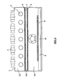
- a first embodiment of an apparatus for drying the printing plates comprises the following elements, from the bottom of the figures: an extractable box comprising a base element 9 for carrying the printing plates 8; above the printing plates, preferably two interspaced sheets of tempered glass, 5 and 6; above the glass sheets, a lighting system 1, described in details below, inside a tank for air depression 2.
- Suitable fan systems 3 and 10 are also provided for the air circulation, as described below.
- the apparatus is divided in three layers, L1, L2 and L3.
- the lower layer L1 forms a chamber for hosting the printing plates to be dried.
- An hollow space above the plates 8 is created possibly having the glass sheet 6 as a cap: an air flow is created by air inlet 11 and air outlet where a fan system 10 is located.
- the arrow shows the air flow direction.
- a light flow of low velocity room temperature air is created, preferably in the range of 0.1 to 0.5 m/s, for taking the solvent vapour emanating from the plates away.
- the air is someway heated by the hot temperature developed over the plates, around 60°C. Due to the low velocity of the air, the temperature gradient inside the plate chamber is also low, and this is an advantage for the better uniformity of temperature inside the chamber.
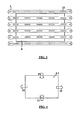
- a preferred scheme of air flow in the chamber L1 is as shown in fig. 4 , with two air inlets 11 at opposite sides with respect to two air outlets 10. This allows a further reduction of temperature gradient inside the chamber.
- An air purification system is connected to the air outlets 10, and can be dimensioned according to the average air flow in the chamber L1. With a drying time of 20 min, a total air flow of 10 m 3 is enough.
- the air purification system can be of any known type, preferably of the refrigeratory type. This because the solvent includes a volatile component (aliphatic alchool) that can also be completely recovered through a system like this.
- a volatile component aliphatic alchool
- the whole of the solvent can be recovered this way, by air condensation.
- a quantity of about 50 cc of solvent is recovered for each millimeter of plate thickness.
- the upper layer L3 forms a chamber for hosting the lighting system 1.
- the glass sheet 5 is the floor of the chamber, while the cap is a tank 2 for air depression.
- the lighting system 1 must be suitable to the purpose of creating a uniform irradiation of visible light wavelengths towards the plates located in the lower layer L1, as all the points of the plate surface must receive the same quantity of light rays, namely the same energy and temperature.
- the difference in the level of irradiation in the different points of the plate surface 8 has to remain within a range of 6-7 %.
- An embodiment of the lighting system 1 is shown in fig. 3 . It comprises a number of parallel normal quartz lamps 1, having a particular geometry depending on the distance from the plates, for irradiation of of visible light wavelengths, with a preferred emission in the range of red wavelengths (400 - 780 nm), so as to generate heating. An unavoidable parasitic emission in the range of infrared wavelengths is also present, to be eliminated as described below.
- Each lamp irradiates with an intensity decreasing more or less linearly with the angle of irradiation; putting the lamps at a relative distance equal to that with respect to the plates, in the different points of the plates the total irradiation is given by the sum of the contributions of two contiguous lamps with a mutual compensation, so giving a uniform level of irradiation in the different points.
- Each lamp has a series of lighting sectors 12 with an individual length equal to the distance between them and equal to the distance between the different lamps, so as to form a complete two-dimensional grid of lighting sectors.
- this common distance is 40 mm.
- the dimensions of the grid of lighting sectors of the lamps exceeds that of the plate surface 8 to be lighted by a value equal to the common distance.
- the dimensions of the grid of lighting sectors will be 1400 x 2080 mm.
- the power supply voltage of the quartz lamps depends on the total length of the lighting sectors of the lamp. Therefore the lamps are so designed as to be supplied by normal existing power supply voltage, for example a three-phase 400 V. In some installations with a considerable total length to be lighted, it is possible to put two or more lamps connected in series, so as each lamp can be still powered by available voltage.
- a cooling system for the lamps is obtained.
- a clean room-temperature air which does not need any purification action, enters the chamber L3 from air inlets 4, makes a cooling action passing through the lamps, and is taken away from the air outlet 3, by a suitable fan system on the cap 2.
- the intermediate layer L2 in between the two glass sheets 5 and 6 is created to eliminate the effects of the parasitic infrared emission by the lighting system 1, and transparent to the wanted visible light wavelengths, which pass through and reach the lower layer L1.
- the sheet 5 nearer to the lamps reflects a part of infrared emission back towards the lamps; a remaining part of infrared wavelengths is refracted towards the other sheet 6 and reflected back. This remaining part reflects and bounces in the interspace 7 between the two sheets: the relating energy is dissipated by generating heating which is taken away by a suitable air flow. This is a clean room-temperature air which does not need any purification action.
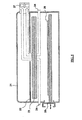
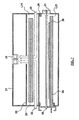
- a second embodiment of the apparatus for drying the printing plates is shown in figures 5 and 6 in a first variant, and in figures 7 and 8 in a second variant.
- a lighting system having normal incandescent lamps 23, preferably of linear filament shape disposed parallel over a printing plate 26 to be dried, so as to generate heating.
- An unavoidable parasitic emission in the range of infrared wavelengths is also present, to be possibly eliminated as described below.
- the plate is put on a base element 25 preferably in an extractable box.
- a reflector 22 is present above the lamps 23, so as to concentrate the most of the irradiation on the direction of the plate 26, and to ensure a uniform lighting level in all the points of the surface to be lighted.
- the reflector 22 can be made of a surface of smoothed aluminium, to get the maximum reflection efficiency.
- the apparatus comprises a body 21, enclosing all the elements in one layer only.
- a number of openings 24 is obtained in the walls of the body, as well as a number of openings or slots 28 is present in the reflector 22.
- a fan system 27 is present above the reflector 22, so as to create a flow of air (dotted arrows) through the openings 24 and 28. The air passes over the plate and takes the solvent vapour emanating from the heated plate away, and it takes also the heat from the plate away, keeping the plate at a temperature below 60°C, as needed.
- the flow of air needed is a strong one, with a typical value of about 350 m 3 per hour. This way the negative effect of the parasitic emission of infrared rays from the lamps is eliminated, as the flow of air cools mainly the surface of the plate, just where the most of the heating caused by the infrared rays is generated.
- This first variant is simple and cheap to reach the main purpose of the present invention.
- due to the huge flow of air needed in practice it is hard to realize a recovery system for the solvent vapour emanating from the plate.
- the apparatus comprises two layers L11 and L21, divided by one tempered glass sheet 29.
- the lamps 23 and the reflector 22 In the upper layer L11 above the glass sheet 29 there are the lamps 23 and the reflector 22.
- the printing plate 26 and the base element 25 In the lower layer L21 there are the printing plate 26 and the base element 25.
- a number of openings 32 is obtained in the walls of the upper part of the body, as well as a number of openings or slots 28 in the reflector 22.
- a fan system 33 is present above the reflector 22, so as to create a first flow of air (dotted arrows) through the openings 32 and 28. This first flow of air cools the lamps 23.
- the parasitic emission of infrared rays from the lamps is eliminated by reflection or absorption of the tempered glass sheet 29 in which a suitable IR filter is present.
- the relating heating effect is taken away by the first flow of air.
- a number of openings 30 is obtained in the walls of the lower part of the body in the lower layer L21, and a fan system 31 is present aside and just above the plate, so as to create a second flow of air through the openings 30, passing over the plate and to the purpose of both cooling the plate, keeping it a a temperature below 60°C, and taking the solvent vapour emanating from the heated plate away.
- the second flow of air is a light flow of low velocity room temperature air, making it possible to implement a recovery system for the solvent vapour emanating from the plate, for example of the kind described above.
- Typical values for the two flows of air are about 350 m 3 per hour for the first flow, and 20 m 3 per hour for the second flow.
- the tests have been performed using printing plates for flexography having different thickness, for example 1,74 mm and 7 mm. For each thickness a squared sample has been taken of 10 cm x 10 cm wide.
- the sample has been exposed to UVA rays for the polymerization step. Then it has been weighted with a very precise balance and thereafter processed with solvent for the normal time needed depending on the thickness and type of the plate. Then it has been weighted again, and dried with the incandescent lamps of the second embodiment, having a spectral emission as shown in fig. 9 .
- the sample has been weighted every 5 th minute, till when it has reached the starting weight again (that it had before the processing with the solvent)
- Fig 9 shows the trend of the power (in mW) with the wavelength (in nm) of the incandescent lamps.
- Fig. 10 shows the trend, with the wavelength (in nm) of the incandescent lamps, of the absorption per cent A% for different types of printing plates having different color (the type of dotted or full lines identifies the color of the plate, respectively red, green, yellow, blu).
- the absorption per cent for the given wavelength in the plate the better the effect of migration of the solvent to the outside of the plate. It is evident that the best result for the absorption process is obtained in the range of 400-650 nm.
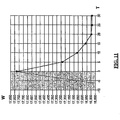
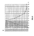
- Figures 11 and 12 show, for a plate sample of respectively 1,74 mm and 7 mm thickness, the trend with the time T of the weight W of the sample in the solvent absorption step (left side) and in the drying step (right side).
- the weight of the solvent absorbed by the plate is 1 g, while in the second case ( fig. 12 ) is 2 g.
- the time necessary for the drying step does not depend on the plate thickness and is very short as compared with the drying time needed with the methods known in the art.
- the lighting system of the second embodiment of the apparatus for drying the printing plates shows a much lower level of emission of parasitic infrared rays than the first one, so the presence of the tempered glass sheet may not be necessary in the most of the practical applications.
Landscapes
- Engineering & Computer Science (AREA)
- Manufacturing & Machinery (AREA)
- Physics & Mathematics (AREA)
- General Physics & Mathematics (AREA)
- Drying Of Solid Materials (AREA)
Claims (40)
- Procédé pour le séchage de plaques d'impression flexographiques, de sorte à laisser s'évaporer un solvant présent à l'intérieur des plaques, caractérisé en ce qu'il comprend l'étape consistant à chauffer les plaques d'impression par irradiation de longueurs d'onde de lumière visible.
- Procédé selon la revendication 1, caractérisé en ce que ladite irradiation de longueurs d'onde de lumière visible se situe dans la plage de longueurs d'onde allant de 400 à 650 nm.
- Procédé selon la revendication 1, caractérisé en ce qu'il comprend également l'étape consistant à laisser un flux d'air passer sur les plaques pour tenir à distance la vapeur de solvant émanant des plaques et pour refroidir les plaques.
- Procédé selon la revendication 3, caractérisé en ce que le flux d'air s'écoule à une faible vitesse, de préférence dans la plage allant de 0,1 à 0,3 m/s et est à température ambiante.
- Procédé selon la revendication 3, caractérisé en ce que ledit air passant sur les plaques est amené dans un système de purification d'air pour récupérer le solvant.
- Procédé selon la revendication 1, caractérisé en ce que ladite irradiation de longueurs d'onde de lumière visible est rendue uniforme sur les plaques.
- Procédé selon la revendication 1, caractérisé en ce que ladite irradiation de longueurs d'onde de lumière visible est constituée d'un certain nombre de lampes placées sur les plaques d'impression.
- Procédé selon la revendication 7, caractérisé en ce que ledit nombre de lampes est des lampes à quartz ou des lampes à incandescence.
- Procédé selon la revendication 7, caractérisé en ce que ledit nombre de lampes est placé dans une couche séparée de la couche de plaque, par une couche intermédiaire transparente aux longueurs d'onde de lumière visible.
- Procédé selon la revendication 7, caractérisé en ce que ledit nombre de lampes sont refroidies par un flux d'air pur et à température ambiante.
- Procédé selon la revendication 9, caractérisé en ce que ladite couche intermédiaire peut éliminer une émission parasite de longueurs d'onde infrarouge par ledit nombre de lampes.
- Appareil pour le séchage de plaques d'impression flexographiques, de sorte à laisser s'évaporer un solvant présent à l'intérieur des plaques, caractérisé en ce qu'il comprend :- un élément de base (9, 25) pour porter les plaques d'impression (8, 26) ;- un système d'éclairage (1, 23) au-dessus des plaques d'impression pour chauffer les plaques d'impression par irradiation de longueurs d'onde de lumière visible.
- Appareil selon la revendication 12, caractérisé en ce que ladite irradiation de longueurs d'onde de lumière visible se situe dans la plage de longueurs d'onde allant de 400 à 650 nm.
- Appareil selon la revendication 12, caractérisé en ce que ledit système d'éclairage (1, 23) crée une irradiation uniforme de longueurs d'onde de lumière visible sur les plaques, même au niveau des frontières de l'élément de base.
- Appareil selon la revendication 12, caractérisé en ce que ledit système d'éclairage (1, 23) comprend un certain nombre de lampes à quartz (1).
- Appareil selon la revendication 15, caractérisé en ce que ledit nombre de lampes à quartz (1) sont disposées en parallèle, à une distance relative égale à celle par rapport aux plaques.
- Appareil selon la revendication 16, caractérisé en ce que chacune desdites lampes à quartz comprend une série de secteurs d'éclairage (12) avec une longueur individuelle égale à la distance entre eux et égale à la distance entre les différentes lampes, de sorte à former une grille bidimensionnelle complète de secteurs d'éclairage.
- Appareil selon la revendication 17, caractérisé en ce que les dimensions de la grille de secteurs d'éclairage dépassent celles de la surface de plaque (8) d'une valeur égale à ladite distance.
- Appareil selon la revendication 15, caractérisé en ce qu'il comprend en outre une première couche intermédiaire (L2) entre l'élément de base (9) et les lampes à quartz (1), pour éliminer les effets de l'émission infrarouge parasite par lesdites lampes à quartz (1), et transparente aux longueurs d'onde de lumière visible.
- Appareil selon la revendication 19, caractérisé en ce qu'il comprend en outre un premier moyen (10, 11) pour créer un flux d'air sur les plaques, pour tenir à distance la vapeur de solvant émanant des plaques et pour refroidir les plaques.
- Appareil selon la revendication 20, caractérisé en ce que ledit flux d'air s'écoule à une faible vitesse et est à température ambiante, de préférence dans la plage allant de 0,1 à 0,3 m/s.
- Appareil selon la revendication 21, caractérisé en ce qu'il comprend en outre un système de purification d'air recevant ledit flux d'air de faible vitesse et à température ambiante, pour récupérer ledit solvant.
- Appareil selon la revendication 22, caractérisé en ce que ledit système de purification d'air est du type réfrigérant.
- Appareil selon la revendication 19, caractérisé en ce que ladite première couche intermédiaire (L2) comprend deux feuilles espacées en verre trempé (5, 6).
- Appareil selon la revendication 24, caractérisé en ce que ladite première couche intermédiaire (L2) comprend un premier système de refroidissement créant un flux d'air dans ledit espacement.
- Appareil selon la revendication 15, caractérisé en ce qu'il comprend un deuxième système de refroidissement (3, 4) pour lesdites lampes à quartz (1).
- Appareil selon la revendication 12, caractérisé en ce que ledit système d'éclairage (1, 23) comprend un certain nombre de lampes à incandescence (23).
- Appareil selon la revendication 27, caractérisé en ce que lesdites lampes à incandescence (23) ont la forme d'un filament linéaire disposé en parallèle sur lesdites plaques d'impression.
- Appareil selon la revendication 28, caractérisé en ce qu'il comprend en outre un réflecteur (22) au-dessus dudit nombre de lampes à incandescence.
- Appareil selon la revendication 29, caractérisé en ce que ledit réflecteur (22) est constitué d'une surface en aluminium lissé.
- Appareil selon la revendication 27, caractérisé en ce qu'il comprend en outre une seconde couche intermédiaire (29) entre l'élément de base (25) et les lampes à incandescence (23), pour éliminer les effets de l'émission infrarouge parasite par lesdites lampes à quartz (1), et transparente aux longueurs d'onde de lumière visible.
- Appareil selon la revendication 31, caractérisé en ce qu'il comprend en outre un deuxième moyen (30, 31) pour créer un flux d'air sur les plaques, pour tenir à distance la vapeur de solvant émanant des plaques et pour refroidir les plaques.
- Appareil selon la revendication 32, caractérisé en ce que ledit flux d'air s'écoule à une faible vitesse et est à température ambiante, de préférence dans la plage allant de 0,1 à 0,3 m/s.
- Appareil selon la revendication 33, caractérisé en ce qu'il comprend en outre un système de purification d'air recevant ledit flux d'air de faible vitesse et à température ambiante, pour récupérer ledit solvant.
- Appareil selon la revendication 31, caractérisé en ce que ladite seconde couche intermédiaire (29) comprend une feuille en verre trempé.
- Appareil selon la revendication 35, caractérisé en ce qu'il comprend un troisième système de refroidissement (32, 33) pour lesdites lampes à incandescence (23).
- Appareil selon la revendication 27, caractérisé en ce qu'il comprend en outre un troisième moyen (24, 27) pour créer un flux d'air sur les plaques, pour tenir à distance la vapeur de solvant émanant des plaques et pour refroidir les plaques.
- Appareil selon la revendication 37, caractérisé en ce que ledit troisième moyen (24, 27) pour créer un flux d'air sur les plaques peut éliminer les effets de l'émission infrarouge parasite par lesdites lampes à incandescence (23).
- Appareil selon la revendication 27, caractérisé en ce que lesdites lampes à incandescence (23) sont refroidies par ledit troisième moyen (24, 27) pour créer un flux d'air sur les plaques.
- Appareil selon la revendication 12, caractérisé en ce qu'il comprend en outre un moyen pour réguler la température des plaques d'impression de sorte à rester inférieure à 60 °C.
Priority Applications (1)
| Application Number | Priority Date | Filing Date | Title |
|---|---|---|---|
| EP05752681A EP1766477B1 (fr) | 2004-06-10 | 2005-06-08 | Procédé et appareil pour le séchage des plaques d'impression flexographiques |
Applications Claiming Priority (3)
| Application Number | Priority Date | Filing Date | Title |
|---|---|---|---|
| EP04102647A EP1605309A1 (fr) | 2004-06-10 | 2004-06-10 | Procédé et appareil pour le séchage des plaques d'impression flexographiques |
| PCT/EP2005/052650 WO2005121898A1 (fr) | 2004-06-10 | 2005-06-08 | Procede et dispositif de sechage de cliches de flexographie |
| EP05752681A EP1766477B1 (fr) | 2004-06-10 | 2005-06-08 | Procédé et appareil pour le séchage des plaques d'impression flexographiques |
Publications (2)
| Publication Number | Publication Date |
|---|---|
| EP1766477A1 EP1766477A1 (fr) | 2007-03-28 |
| EP1766477B1 true EP1766477B1 (fr) | 2008-05-14 |
Family
ID=34929190
Family Applications (2)
| Application Number | Title | Priority Date | Filing Date |
|---|---|---|---|
| EP04102647A Withdrawn EP1605309A1 (fr) | 2004-06-10 | 2004-06-10 | Procédé et appareil pour le séchage des plaques d'impression flexographiques |
| EP05752681A Expired - Lifetime EP1766477B1 (fr) | 2004-06-10 | 2005-06-08 | Procédé et appareil pour le séchage des plaques d'impression flexographiques |
Family Applications Before (1)
| Application Number | Title | Priority Date | Filing Date |
|---|---|---|---|
| EP04102647A Withdrawn EP1605309A1 (fr) | 2004-06-10 | 2004-06-10 | Procédé et appareil pour le séchage des plaques d'impression flexographiques |
Country Status (6)
| Country | Link |
|---|---|
| US (1) | US20060130688A1 (fr) |
| EP (2) | EP1605309A1 (fr) |
| AT (1) | ATE395633T1 (fr) |
| CA (1) | CA2569777A1 (fr) |
| DE (1) | DE602005006812D1 (fr) |
| WO (1) | WO2005121898A1 (fr) |
Families Citing this family (3)
| Publication number | Priority date | Publication date | Assignee | Title |
|---|---|---|---|---|
| DE102005013794A1 (de) * | 2005-03-24 | 2006-09-28 | Alstom Technology Ltd. | Leitschaufel für eine Strömungsrotationsmaschine |
| JP2017518534A (ja) | 2014-06-03 | 2017-07-06 | フリント グループ ジャーマニー ゲーエムベーハー | 速乾性フレキソ印刷構成部材 |
| EP4730041A1 (fr) * | 2024-10-21 | 2026-04-22 | Vianord Engineering Sasu | Procédé de séchage d'une plaque d'impression numérique pour flexographie |
Family Cites Families (5)
| Publication number | Priority date | Publication date | Assignee | Title |
|---|---|---|---|---|
| US4478931A (en) * | 1982-09-27 | 1984-10-23 | E. I. Du Pont De Nemours And Company | Precurled flexographic printing plate |
| CH671231A5 (fr) * | 1985-07-24 | 1989-08-15 | Basf Ag | |
| US5966836A (en) * | 1997-04-11 | 1999-10-19 | Howard W. DeMoore | Infrared heating apparatus and method for a printing press |
| AU2003299180A1 (en) * | 2002-10-04 | 2004-04-23 | Agfa-Gevaert | Method of marking a lithographic printing plate precursor |
| US6794107B2 (en) * | 2002-10-28 | 2004-09-21 | Kodak Polychrome Graphics Llc | Thermal generation of a mask for flexography |
-
2004
- 2004-06-10 EP EP04102647A patent/EP1605309A1/fr not_active Withdrawn
-
2005
- 2005-06-08 WO PCT/EP2005/052650 patent/WO2005121898A1/fr not_active Ceased
- 2005-06-08 AT AT05752681T patent/ATE395633T1/de not_active IP Right Cessation
- 2005-06-08 EP EP05752681A patent/EP1766477B1/fr not_active Expired - Lifetime
- 2005-06-08 CA CA002569777A patent/CA2569777A1/fr not_active Abandoned
- 2005-06-08 DE DE602005006812T patent/DE602005006812D1/de not_active Expired - Fee Related
- 2005-06-10 US US11/150,405 patent/US20060130688A1/en not_active Abandoned
Also Published As
| Publication number | Publication date |
|---|---|
| WO2005121898A1 (fr) | 2005-12-22 |
| ATE395633T1 (de) | 2008-05-15 |
| CA2569777A1 (fr) | 2005-12-22 |
| DE602005006812D1 (de) | 2008-06-26 |
| EP1766477A1 (fr) | 2007-03-28 |
| EP1605309A1 (fr) | 2005-12-14 |
| US20060130688A1 (en) | 2006-06-22 |
Similar Documents
| Publication | Publication Date | Title |
|---|---|---|
| US6807906B1 (en) | Zoned ultraviolet curing system for printing press | |
| KR101809303B1 (ko) | 자기적으로 유도된 시각 효과를 생성하는 장치, 시스템 및 방법 | |
| US8272729B2 (en) | Ink jet printer and a process of ink jet printing | |
| EP1766477B1 (fr) | Procédé et appareil pour le séchage des plaques d'impression flexographiques | |
| US7669530B2 (en) | UV curing assembly having sheet transfer unit with heat sink vacuum plate | |
| US4924599A (en) | UV curing apparatus | |
| JPH0245148A (ja) | 紫外線発生装置を設けた乾燥部 | |
| US5667850A (en) | Method of curing with ultraviolet radiation on substrates requiring low heat | |
| US20150336372A1 (en) | Screen Printing Device and Method | |
| US6984830B2 (en) | Apparatus for limited-heat curing of photosensitive coatings and inks | |
| DK1245385T3 (da) | Vådoffset-trykform med fototermisk foranderligt materiale, fremgangsmåde og indretning til frembringelse og/eller sletning af et trykbillede fra en vådoffset-trykform | |
| US3159464A (en) | Method of drying printed webs | |
| TWI857213B (zh) | 乾燥裝置 | |
| ATE42240T1 (de) | Laminierungsverfahren und -vorrichtung. | |
| JP2840521B2 (ja) | インキ画像乾燥装置を有する孔版印刷装置 | |
| CN223821288U (zh) | 一种高速印刷用多级同步烘干装置 | |
| CN208334905U (zh) | 一种太阳能曝光机uvled专用光源系统 | |
| US11781810B2 (en) | Drying device | |
| JPS6310817Y2 (fr) | ||
| JPH09127300A (ja) | 紫外線照射装置 | |
| Stowe | High-power UV lamps for industrial UV curing applications | |
| JPS5546739A (en) | Light source of contact photographic printer for e.p.m. | |
| US20210331491A1 (en) | Printing fluid dryer | |
| KR101699871B1 (ko) | 인쇄 장치 및 이를 이용한 인쇄 방법 | |
| CA1280086C (fr) | Dispositif pour le traitement de substances par les rayons uv |
Legal Events
| Date | Code | Title | Description |
|---|---|---|---|
| PUAI | Public reference made under article 153(3) epc to a published international application that has entered the european phase |
Free format text: ORIGINAL CODE: 0009012 |
|
| 17P | Request for examination filed |
Effective date: 20070108 |
|
| AK | Designated contracting states |
Kind code of ref document: A1 Designated state(s): AT BE BG CH CY CZ DE DK EE ES FI FR GB GR HU IE IS IT LI LT LU MC NL PL PT RO SE SI SK TR |
|
| DAX | Request for extension of the european patent (deleted) | ||
| GRAP | Despatch of communication of intention to grant a patent |
Free format text: ORIGINAL CODE: EPIDOSNIGR1 |
|
| GRAS | Grant fee paid |
Free format text: ORIGINAL CODE: EPIDOSNIGR3 |
|
| GRAA | (expected) grant |
Free format text: ORIGINAL CODE: 0009210 |
|
| AK | Designated contracting states |
Kind code of ref document: B1 Designated state(s): AT BE BG CH CY CZ DE DK EE ES FI FR GB GR HU IE IS IT LI LT LU MC NL PL PT RO SE SI SK TR |
|
| REG | Reference to a national code |
Ref country code: GB Ref legal event code: FG4D |
|
| REG | Reference to a national code |
Ref country code: CH Ref legal event code: EP |
|
| REG | Reference to a national code |
Ref country code: IE Ref legal event code: FG4D Free format text: LANGUAGE OF EP DOCUMENT: FRENCH |
|
| REF | Corresponds to: |
Ref document number: 602005006812 Country of ref document: DE Date of ref document: 20080626 Kind code of ref document: P |
|
| PG25 | Lapsed in a contracting state [announced via postgrant information from national office to epo] |
Ref country code: SI Free format text: LAPSE BECAUSE OF FAILURE TO SUBMIT A TRANSLATION OF THE DESCRIPTION OR TO PAY THE FEE WITHIN THE PRESCRIBED TIME-LIMIT Effective date: 20080514 |
|
| PG25 | Lapsed in a contracting state [announced via postgrant information from national office to epo] |
Ref country code: FI Free format text: LAPSE BECAUSE OF FAILURE TO SUBMIT A TRANSLATION OF THE DESCRIPTION OR TO PAY THE FEE WITHIN THE PRESCRIBED TIME-LIMIT Effective date: 20080514 Ref country code: ES Free format text: LAPSE BECAUSE OF FAILURE TO SUBMIT A TRANSLATION OF THE DESCRIPTION OR TO PAY THE FEE WITHIN THE PRESCRIBED TIME-LIMIT Effective date: 20080825 |
|
| NLV1 | Nl: lapsed or annulled due to failure to fulfill the requirements of art. 29p and 29m of the patents act | ||
| PG25 | Lapsed in a contracting state [announced via postgrant information from national office to epo] |
Ref country code: AT Free format text: LAPSE BECAUSE OF FAILURE TO SUBMIT A TRANSLATION OF THE DESCRIPTION OR TO PAY THE FEE WITHIN THE PRESCRIBED TIME-LIMIT Effective date: 20080514 Ref country code: PL Free format text: LAPSE BECAUSE OF FAILURE TO SUBMIT A TRANSLATION OF THE DESCRIPTION OR TO PAY THE FEE WITHIN THE PRESCRIBED TIME-LIMIT Effective date: 20080514 Ref country code: NL Free format text: LAPSE BECAUSE OF FAILURE TO SUBMIT A TRANSLATION OF THE DESCRIPTION OR TO PAY THE FEE WITHIN THE PRESCRIBED TIME-LIMIT Effective date: 20080514 |
|
| PG25 | Lapsed in a contracting state [announced via postgrant information from national office to epo] |
Ref country code: IS Free format text: LAPSE BECAUSE OF FAILURE TO SUBMIT A TRANSLATION OF THE DESCRIPTION OR TO PAY THE FEE WITHIN THE PRESCRIBED TIME-LIMIT Effective date: 20080914 |
|
| PG25 | Lapsed in a contracting state [announced via postgrant information from national office to epo] |
Ref country code: SE Free format text: LAPSE BECAUSE OF FAILURE TO SUBMIT A TRANSLATION OF THE DESCRIPTION OR TO PAY THE FEE WITHIN THE PRESCRIBED TIME-LIMIT Effective date: 20080814 Ref country code: LT Free format text: LAPSE BECAUSE OF FAILURE TO SUBMIT A TRANSLATION OF THE DESCRIPTION OR TO PAY THE FEE WITHIN THE PRESCRIBED TIME-LIMIT Effective date: 20080514 Ref country code: DK Free format text: LAPSE BECAUSE OF FAILURE TO SUBMIT A TRANSLATION OF THE DESCRIPTION OR TO PAY THE FEE WITHIN THE PRESCRIBED TIME-LIMIT Effective date: 20080514 Ref country code: MC Free format text: LAPSE BECAUSE OF NON-PAYMENT OF DUE FEES Effective date: 20080630 Ref country code: CZ Free format text: LAPSE BECAUSE OF FAILURE TO SUBMIT A TRANSLATION OF THE DESCRIPTION OR TO PAY THE FEE WITHIN THE PRESCRIBED TIME-LIMIT Effective date: 20080514 |
|
| PG25 | Lapsed in a contracting state [announced via postgrant information from national office to epo] |
Ref country code: SK Free format text: LAPSE BECAUSE OF FAILURE TO SUBMIT A TRANSLATION OF THE DESCRIPTION OR TO PAY THE FEE WITHIN THE PRESCRIBED TIME-LIMIT Effective date: 20080514 Ref country code: BE Free format text: LAPSE BECAUSE OF FAILURE TO SUBMIT A TRANSLATION OF THE DESCRIPTION OR TO PAY THE FEE WITHIN THE PRESCRIBED TIME-LIMIT Effective date: 20080514 Ref country code: RO Free format text: LAPSE BECAUSE OF FAILURE TO SUBMIT A TRANSLATION OF THE DESCRIPTION OR TO PAY THE FEE WITHIN THE PRESCRIBED TIME-LIMIT Effective date: 20080514 Ref country code: PT Free format text: LAPSE BECAUSE OF FAILURE TO SUBMIT A TRANSLATION OF THE DESCRIPTION OR TO PAY THE FEE WITHIN THE PRESCRIBED TIME-LIMIT Effective date: 20081014 |
|
| PLBE | No opposition filed within time limit |
Free format text: ORIGINAL CODE: 0009261 |
|
| STAA | Information on the status of an ep patent application or granted ep patent |
Free format text: STATUS: NO OPPOSITION FILED WITHIN TIME LIMIT |
|
| 26N | No opposition filed |
Effective date: 20090217 |
|
| PG25 | Lapsed in a contracting state [announced via postgrant information from national office to epo] |
Ref country code: BG Free format text: LAPSE BECAUSE OF FAILURE TO SUBMIT A TRANSLATION OF THE DESCRIPTION OR TO PAY THE FEE WITHIN THE PRESCRIBED TIME-LIMIT Effective date: 20080814 Ref country code: EE Free format text: LAPSE BECAUSE OF FAILURE TO SUBMIT A TRANSLATION OF THE DESCRIPTION OR TO PAY THE FEE WITHIN THE PRESCRIBED TIME-LIMIT Effective date: 20080514 Ref country code: IE Free format text: LAPSE BECAUSE OF NON-PAYMENT OF DUE FEES Effective date: 20080608 Ref country code: DE Free format text: LAPSE BECAUSE OF NON-PAYMENT OF DUE FEES Effective date: 20090101 |
|
| PG25 | Lapsed in a contracting state [announced via postgrant information from national office to epo] |
Ref country code: IT Free format text: LAPSE BECAUSE OF FAILURE TO SUBMIT A TRANSLATION OF THE DESCRIPTION OR TO PAY THE FEE WITHIN THE PRESCRIBED TIME-LIMIT Effective date: 20080514 |
|
| REG | Reference to a national code |
Ref country code: CH Ref legal event code: PL |
|
| GBPC | Gb: european patent ceased through non-payment of renewal fee |
Effective date: 20090608 |
|
| PG25 | Lapsed in a contracting state [announced via postgrant information from national office to epo] |
Ref country code: CH Free format text: LAPSE BECAUSE OF NON-PAYMENT OF DUE FEES Effective date: 20090630 Ref country code: LI Free format text: LAPSE BECAUSE OF NON-PAYMENT OF DUE FEES Effective date: 20090630 |
|
| PG25 | Lapsed in a contracting state [announced via postgrant information from national office to epo] |
Ref country code: GB Free format text: LAPSE BECAUSE OF NON-PAYMENT OF DUE FEES Effective date: 20090608 |
|
| PG25 | Lapsed in a contracting state [announced via postgrant information from national office to epo] |
Ref country code: LU Free format text: LAPSE BECAUSE OF NON-PAYMENT OF DUE FEES Effective date: 20080608 Ref country code: HU Free format text: LAPSE BECAUSE OF FAILURE TO SUBMIT A TRANSLATION OF THE DESCRIPTION OR TO PAY THE FEE WITHIN THE PRESCRIBED TIME-LIMIT Effective date: 20081115 Ref country code: CY Free format text: LAPSE BECAUSE OF FAILURE TO SUBMIT A TRANSLATION OF THE DESCRIPTION OR TO PAY THE FEE WITHIN THE PRESCRIBED TIME-LIMIT Effective date: 20080514 |
|
| PG25 | Lapsed in a contracting state [announced via postgrant information from national office to epo] |
Ref country code: TR Free format text: LAPSE BECAUSE OF FAILURE TO SUBMIT A TRANSLATION OF THE DESCRIPTION OR TO PAY THE FEE WITHIN THE PRESCRIBED TIME-LIMIT Effective date: 20080514 |
|
| PG25 | Lapsed in a contracting state [announced via postgrant information from national office to epo] |
Ref country code: GR Free format text: LAPSE BECAUSE OF FAILURE TO SUBMIT A TRANSLATION OF THE DESCRIPTION OR TO PAY THE FEE WITHIN THE PRESCRIBED TIME-LIMIT Effective date: 20080815 |
|
| REG | Reference to a national code |
Ref country code: FR Ref legal event code: ST Effective date: 20110722 |
|
| PG25 | Lapsed in a contracting state [announced via postgrant information from national office to epo] |
Ref country code: FR Free format text: LAPSE BECAUSE OF NON-PAYMENT OF DUE FEES Effective date: 20080715 |