EP1766633B1 - Centrale nucleaire et methode - Google Patents
Centrale nucleaire et methode Download PDFInfo
- Publication number
- EP1766633B1 EP1766633B1 EP05738372.1A EP05738372A EP1766633B1 EP 1766633 B1 EP1766633 B1 EP 1766633B1 EP 05738372 A EP05738372 A EP 05738372A EP 1766633 B1 EP1766633 B1 EP 1766633B1
- Authority
- EP
- European Patent Office
- Prior art keywords
- ionised
- flow path
- radioisotopes
- isotopes
- deposition
- Prior art date
- Legal status (The legal status is an assumption and is not a legal conclusion. Google has not performed a legal analysis and makes no representation as to the accuracy of the status listed.)
- Expired - Lifetime
Links
Images


Classifications
-
- G—PHYSICS
- G21—NUCLEAR PHYSICS; NUCLEAR ENGINEERING
- G21C—NUCLEAR REACTORS
- G21C1/00—Reactor types
- G21C1/04—Thermal reactors ; Epithermal reactors
- G21C1/06—Heterogeneous reactors, i.e. in which fuel and moderator are separated
- G21C1/07—Pebble-bed reactors; Reactors with granular fuel
-
- G—PHYSICS
- G21—NUCLEAR PHYSICS; NUCLEAR ENGINEERING
- G21C—NUCLEAR REACTORS
- G21C3/00—Reactor fuel elements and their assemblies; Selection of substances for use as reactor fuel elements
- G21C3/30—Assemblies of a number of fuel elements in the form of a rigid unit
- G21C3/32—Bundles of parallel pin-, rod-, or tube-shaped fuel elements
- G21C3/3206—Means associated with the fuel bundle for filtering the coolant, e.g. nozzles, grids
-
- G—PHYSICS
- G21—NUCLEAR PHYSICS; NUCLEAR ENGINEERING
- G21C—NUCLEAR REACTORS
- G21C19/00—Arrangements for treating, for handling, or for facilitating the handling of, fuel or other materials which are used within the reactor, e.g. within its pressure vessel
- G21C19/28—Arrangements for introducing fluent material into the reactor core; Arrangements for removing fluent material from the reactor core
- G21C19/30—Arrangements for introducing fluent material into the reactor core; Arrangements for removing fluent material from the reactor core with continuous purification of circulating fluent material, e.g. by extraction of fission products deterioration or corrosion products, impurities, e.g. by cold traps
- G21C19/307—Arrangements for introducing fluent material into the reactor core; Arrangements for removing fluent material from the reactor core with continuous purification of circulating fluent material, e.g. by extraction of fission products deterioration or corrosion products, impurities, e.g. by cold traps specially adapted for liquids
-
- G—PHYSICS
- G21—NUCLEAR PHYSICS; NUCLEAR ENGINEERING
- G21C—NUCLEAR REACTORS
- G21C3/00—Reactor fuel elements and their assemblies; Selection of substances for use as reactor fuel elements
-
- G—PHYSICS
- G21—NUCLEAR PHYSICS; NUCLEAR ENGINEERING
- G21C—NUCLEAR REACTORS
- G21C3/00—Reactor fuel elements and their assemblies; Selection of substances for use as reactor fuel elements
- G21C3/30—Assemblies of a number of fuel elements in the form of a rigid unit
- G21C3/32—Bundles of parallel pin-, rod-, or tube-shaped fuel elements
-
- Y—GENERAL TAGGING OF NEW TECHNOLOGICAL DEVELOPMENTS; GENERAL TAGGING OF CROSS-SECTIONAL TECHNOLOGIES SPANNING OVER SEVERAL SECTIONS OF THE IPC; TECHNICAL SUBJECTS COVERED BY FORMER USPC CROSS-REFERENCE ART COLLECTIONS [XRACs] AND DIGESTS
- Y02—TECHNOLOGIES OR APPLICATIONS FOR MITIGATION OR ADAPTATION AGAINST CLIMATE CHANGE
- Y02E—REDUCTION OF GREENHOUSE GAS [GHG] EMISSIONS, RELATED TO ENERGY GENERATION, TRANSMISSION OR DISTRIBUTION
- Y02E30/00—Energy generation of nuclear origin
- Y02E30/30—Nuclear fission reactors
Definitions
- THIS INVENTION relates to a nuclear plant.
- the invention extends to a method of removing particles from a fluid stream.
- JPH11337697 discloses a set-up for deflecting ionised isotopes. This set-up comprises a flow path and pairs of opposing electromagnets that are angularly off-set.
- reference numeral 10 refers generally to part of a nuclear plant.
- the nuclear plant 10 includes a reactor vessel 12 and a fluid circuit, generally indicated by reference numeral 14, including flow path defining means 16, defining a flow path for circulating a reactor coolant fluid from and to the reactor vessel 12.
- the plant 10 will include other components such as coolant fluid circulation means for circulating coolant fluid to and from the reactor vessel.
- details of these components are not required for an understanding of the invention and they are accordingly not shown in the drawings.
- the flow path defining means 16 includes an inner circular cylindrical pipe 18, defining a flow path 19, and an outer circular cylindrical pipe 20, concentric and coaxial with the inner pipe 18.
- An annular cavity 22 is defined between the inner pipe 18 and the outer pipe 20 and a thermal insulating material 24 is interposed between the inner and outer pipes 18, 20 in the annular cavity 22.
- An outermost tubular cylindrical pressure boundary wall 26 is arranged around the inner and outer pipes 18, 20, to be concentric and coaxial therewith.
- Hot coolant gas from the reactor vessel 12 is conveyed, in use, in the direction of the arrow 28 (or in an opposite direction to the arrow 28) through the coolant fluid circuit 14 to drive a power turbine or steam generator or other power conversion device (not shown) and is cooled and compressed prior to being returned to the reactor vessel 12 via the fluid circuit 14.
- the hot coolant gas emanating from the reactor vessel 12 typically contains contaminants including, for example, ionised isotopes and radioisotopes, as well as other ions.
- the nuclear plant 10 includes a magnetic deflection arrangement 30 for applying a magnetic field across the flow path 19 and generating a magnetic field in the flow path 19.
- the magnetic deflection arrangement 30 includes magnets arranged between the pressure boundary wall 26 and the outer pipe 20 at positions along the length of the flow path 19.
- the magnets are permanent magnets (of a ceramic material incorporating rare earth metal(s)). It is to be appreciated, however, that the magnets may instead be electromagnets.
- the nuclear plant 10 may include particle ionisation means 31 ( Figure 1 ), including an ioniser such as a neutron or electromagnetic radiation source eg. X-ray or UV emitter, disposed in the flow path 19 upstream of the magnetic deflection arrangement 30, i.e. between an outlet of the reactor vessel 12 and the magnetic deflection arrangement 30.
- the ionisation means 31 increases the number of charged particles in the fluid stream at the position along the length of the flow path 19 at which the magnetic deflection arrangement 30 is provided, by ionisation of the particles conveyed in the fluid stream prior to their conveyance through that part of the flow path defining means 16 at which the magnetic deflection arrangement 30 is provided.
- the magnetic deflection arrangement 30 includes three pairs 32, 34, 36 of ring segment magnets 38 arranged adjacent to an outer wall 39 of the outer pipe 20 at longitudinally spaced positions.
- the magnets 38 of each pair 32, 34, 36 are located at diametrically positions and are arranged such that poles 40 of opposite polarity of the magnets 38 of any pair 32, 34, 36 face inwardly and outwardly, respectively.
- each pair of magnets 32, 34, 36 comprises a magnet 38 having an outwardly-directed north pole and an inwardly-directed south pole, and an opposed magnet 38 having an outwardly-directed south pole and an inwardly directed north pole.
- the poles 40 of the magnets 38 of each pair 32, 34, 36 are angularly off-set from the poles 40 of the magnets 38 of each other pair 32, 34, 36.
- the poles 40 of the magnets 38 of the pairs 32 and 34, and 34 and 36, respectively are off-set by about 45 degrees.
- the poles 40 of the magnets 38 of the pair 36 are off-set by about 90 degrees relative to those in the pair 32.
- the Inventors are of the view that magnetic fields of approximately constant magnetic flux will be obtained over the cross-section of the pipe 18 at each pair 32, 34, 36 of opposing magnets.
- the poles 40 of the magnets 38 of the pairs 32, 34, 36 may be angularly off-set by other magnitudes of angle.
- the magnetic deflection arrangement 30 includes a toroidal magnet 41 arranged around the outer pipe 20.
- the magnetic deflection arrangement further includes two pairs 42, 44 of magnets 38, similar to the pairs of magnets 32, 34, 36 of Figure 2 , the pairs 42, 44 and magnet 40 being longitudinally spaced along the outer pipe 20, between the pressure boundary wall 26 and the outer pipe 20.
- the magnetic deflection arrangement 30 generates a magnetic field in the flow path 19 such that a particle having a charge, such as an ion in the coolant fluid stream, and moving with a velocity through the magnetic field will experience a force (a Lorentz force) and be deflected from its path of travel towards an internal surface of the inner pipe 18.
- FIG. 4 of the drawings shows part of the flow path defining means 16 of the fluid circuit 14 in longitudinal cross-section and, unless otherwise indicated, the same reference numerals used above are used to designate similar parts.
- An internal surface of the inner pipe 18, defining the flow path 19, has a deposition lining 50 provided thereon.
- the deposition lining 50 defines a particle deposition bed 52 which provides a collection zone into which charged particles, eg. ionised isotopes, can be deflected and embedded (ie. collected and retained) thereby to be removed from the coolant fluid stream.
- the deposition lining 50 comprises a plurality of layers of materials which resist particle diffusion therethrough.
- the lining 50 may include a radially innermost layer 54 of graphite, defining a charged particle landing zone and providing a decelerator for the charged particles.
- the layer 54 may, however, instead be comprised of any other suitable soft temperature-resistant material.
- An intermediate layer 56 of chromium is sandwiched between the graphite layer 54 and an outer layer 58 of silicon carbide.
- the chromium layer 56 provides a trap for silver atoms/ions, which exhibit an affinity for chromium.
- platinum or an alloy resistant to radiation damage such as a Specialty Chromium Alloy, may be used.
- the material of the layer 56 typically attracts captured charged particles through the layer 54 of graphite, or other soft material, into the layer 56.
- the silicon carbide provides an outer barrier layer 58 for inhibiting diffusion of ionised isotopes and other ions through the wall of the inner pipe 18.
- the outer layer 58 may be comprised of SiN, SiFC or diamond.
- That part of the inner pipe 18 having the deposition lining 50 provided thereon may be comprised by a tubular circular cylindrical base element providing a pipe segment which is removably inserted into the fluid circuit 14 to form part of the flow path defining means 16.
- the pipe segment/base element may thus be removed during shutdown or reactor maintenance, typically when the deposition lining 50 is saturated with embedded charged particles, and replaced with another like pipe segment/base element having a fresh deposition lining 50 for particle collection. Saturation of the deposition lining 50 may be determined, for example, on a pre-calculated fixed term basis (i.e. after expiration of a predetermined number of hours of reactor operation) or by active measurement of a saturation level of the deposition lining 50.
- the removed pipe segment/base element will typically be stored on a long term basis.
- the intermediate layer 56 is of a fluid material, such as, for example, mercury or liquid sodium.
- the nuclear plant 10 then typically will include means (not shown) for removing the fluid material of the layer 56 from the deposition lining 50 and providing substitute fluid material therefor or returning the fluid material to the deposition lining 50.
- the nuclear plant 10 will typically include fluid material circulation means (not shown), defining a fluid material flow path, for circulating the fluid material, via secondary particle removal means (not shown), from and to the deposition Hning 50.
- the secondary particle removal means will serve to remove particles collected in the fluid material of the layer 56 from the fluid material during circulation thereof, so that fluid material returned to the deposition lining 50 is purged of particle contaminants.
- the secondary particle removal means may be provided, for example, by a particle collection zone, defined along the length of the fluid material flow path, and particle deflection means (typically a magnet arrangement) arranged in particle deflecting relationship with the fluid material flow path to deflect particles from the fluid material into the particle collection zone.
- the secondary particle removal means may be provided by a biofilter, for removing particles from the fluid deposition material by use of living organisms, typically bacteria, which, for example, may consume the contaminant particles.
- a charged particle collection zone is defined by a series of longitudinally spaced magnetic traps 60, provided on an internal surface of the flow path defining means 16.
- the inner pipe 18 is omitted from that part of the fluid circuit 14 in which the particle collection zone is provided.
- each magnetic trap 60 is provided by a channel-section ring formation 62, having magnetic internal walls 64.
- the ring formations 62 are arranged in side-by-side longitudinally spaced relationship against an internal surface 66 of the outer pipe 20 so as to extend circumferentially around the outer pipe 20 and define longitudinally spaced peripheral channels 68, each providing an endless passage, along the flow path defining means 16.
- the channels 68 are lipped. A magnetic field is generated within each channel 68 by the magnetic internal walls 64 thereof such that a charged particle deflected into a channel 68, by the magnetic field applied across the flow path 19, will be displaced along the endless passage under the influence of the magnetic field of the channel 68 and will thereby be trapped in the relevant channel 38.
- the flow path defining means will typically have an internal diameter of between about 1 metre and about 1,5 metres.
- the deposition bed 52, or, alternatively, the arrangement of channels 68 will extend for a length of between about 2 times to about 5 times the internal diameter, ie. in the present arrangement extending for about 4 metres, along the length of the flow path defining means, and will be positioned as close as possible to an outlet from the reactor vessel 12.
- coolant fluid leaving the reactor vessel 12 is fed through the fluid circuit 16 along the flow path 19.
- the magnetic field arising from the magnetic deflection arrangement 30 interacts with the charged particle products, of nuclear fission reactions in the reactor vessel, which are contained in the coolant fluid stream and the particles are deflected radially outwardly thereby, in the direction of coolant fluid flow 28, toward the internal surface of the flow path defining means 16.
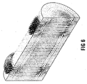
- Figures 6 and 7 of the drawings illustrate the magnetic field and the coercive force field, respectively, for the magnetic deflection arrangement 30 of Figure 3 of the drawings.
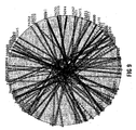
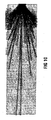
- Figures 8 to 10 illustrate the paths of travel of deflected charged particles in the coolant fluid stream.
- Figures 8 to 10 are for illustrative purposes only, the particles for which deflection pathways are illustrated being simulated particles having masses greater than the atomic masses of known existing elements. It will be appreciated that the magnitude of the force experienced by any particular charged particle, and hence its degree of deflection, will be dependant on the velocity with which the particle moves through the magnetic field applied across the flow path 19 as well as particle properties, such as the particle's mass, charge/degree of ionisation and magnetic moment.
- the particles deflected toward the internal surface of the inner pipe 18 are propelled into the deposition lining 50.
- the particles land on the inner graphite layer 54 where they are decelerated. Some particles are embedded within the graphite layer 54, whilst others pass through the layer 54 into the underlying layer 56 of chromium.
- silver ions have an affinity for the chromium layer 56. Those particles which diffuse through the intermediate chromium layer 56 are finally embedded in the outer silicon carbide layer 58 and diffusion of the charged particles through the inner pipe 18 is thus inhibited.
- the ionised isotopes and other ions are collected and retained in the particle deposition bed 52 comprised by the deposition lining 50 so that the coolant fluid downstream of the deposition bed 52 is purged of these ion or isotope contaminants.
- the wall of the flow path defining means is of a particle diffusion-resistant material and provides the deposition bed without an internal deposition lining being provided.
- a deflected charged particle is propelled into one of the series of longitudinally spaced magnetic traps 60 on an internal surface of the flow path defining means 16.
- the particle is displaced in a spiral motion along the endless passage provided by the channel 68, under the influence of the magnetic field generated within the channel 68 by the magnetic internal walls 64 thereof.
- the fluid stream is thus similarly purged of ionised isotopes and other charged particle contaminants.
- the Applicant believes that the nuclear plant 10 and method of the invention will provide an effective means of removing harmful radioactive contaminants from a coolant fluid of a nuclear power plant. This in turn, it is believed, will render maintenance of the fluid circuit components downstream of the particle collection zone/particle deposition bed 52/magnetic trap arrangement 60 in the nuclear plant 10 a safer activity.
- the method/apparatus of the invention will alleviate build-up of particles in the power conversion unit and other downstream components and reduce the need for maintenance thereof.
- the magnetic deflecting arrangement 30 includes electromagnets, it is believed that pulsating the magnetic field will improve the efficiency of removing the charged particles from the coolant fluid. Further, it is believed that by providing angularly off-set pairs of magnets in the magnetic deflecting arrangement 30, the charged particle removal efficiency is improved.
Landscapes
- Physics & Mathematics (AREA)
- Engineering & Computer Science (AREA)
- Plasma & Fusion (AREA)
- General Engineering & Computer Science (AREA)
- High Energy & Nuclear Physics (AREA)
- Water Treatment By Electricity Or Magnetism (AREA)
- Devices And Processes Conducted In The Presence Of Fluids And Solid Particles (AREA)
- Fluidized-Bed Combustion And Resonant Combustion (AREA)
- Structure Of Emergency Protection For Nuclear Reactors (AREA)
Claims (20)
- Moyen d'élimination de particules comprenant des isotopes ionisés et/ou des radio-isotopes ionisés d'un courant de gaz réfrigérant de réacteur nucléaire d'une centrale nucléaire (10), le moyen comprenantune centrale nucléaire (10) qui inclut un caisson de réacteur nucléaire (12) ainsi qu'un circuit de fluide (14) qui comprend un moyen de définition de chemin d'écoulement (16) ayant une surface interne qui définit un chemin d'écoulement (19) le long duquel le courant de gaz réfrigérant peut être dirigé et mis à circuler depuis et vers le caisson de réacteur nucléaire (12), les isotopes ionisés et/ou radio-isotopes ionisés étant des produits de réactions de fission nucléaire dans le caisson de réacteur nucléaire (12),une zone de collecte de particules comprenant un lit de déposition (52) disposé sur la surface interne du moyen de définition de chemin d'écoulement, lequel lit de déposition (52) inclut un matériau résistant à la diffusion d'isotopes ionisés et/ou de radio-isotopes ionisés (54, 56, 58) dans lequel les isotopes ionisés et/ou radio-isotopes ionisés peuvent être, et sont, en utilisation, noyés, etun agencement de déflection de particules magnétique (30) qui comprend au moins deux paires d'aimants (38), les aimants (38) de chaque paire étant localisés adjacents au moyen de définition de chemin d'écoulement (16) à des positions diamétralement opposées de telle sorte que les aimants (38) de chaque paire aient des pôles diamétralement opposés disposés vers l'intérieur (40) de polarité opposée et des pôles disposés vers l'extérieur de polarité opposée, et les paires étant agencées de façon à avoir des pôles angulairement décalés (40) de polarité identique, angulairement décalés à un angle supérieur à 0 et égal ou plus petit que 45°, les aimants (38) de chaque paire étant ainsi capables de générer, dans le chemin d'écoulement (19), un champ magnétique à travers une section en coupe transversale à une direction d'écoulement du courant de gaz réfrigérant pour défléchir ainsi les isotopes ionisés et/ou radio-isotopes ionisés du courant de gaz réfrigérant du réacteur dans le chemin d'écoulement (19) dans une direction radialement vers l'extérieur par rapport à la direction d'écoulement dans le chemin d'écoulement (19) dans ou vers le matériau de déposition de la zone de collecte de particules de façon à noyer dans le matériau de déposition les isotopes ionisés et/ou radio-isotopes ionisés qui sont ainsi défléchis.
- Moyen selon la revendication 1, dans lequel l'agencement de déflexion magnétique (30) est adapté pour générer un champ magnétique de flux magnétique généralement constant à travers l'aire en coupe transversale à une direction d'écoulement du courant de fluide.
- Moyen selon la revendication 1, dans lequel les pôles (40) de polarité identique des paires d'aimants opposés (38) sont décalés de 45 degrés.
- Moyen selon l'une quelconque des revendications 1 à 3 incluse, dans lequel l'agencement de déflexion magnétique (30) inclut au moins un aimant toroïdal (41) agencé autour du moyen de définition de chemin d'écoulement (16).
- Moyen selon l'une quelconque des revendications 1 à 4 incluse, dans lequel l'agencement de déflexion magnétique inclut au moins un aimant permanent.
- Moyen selon l'une quelconque des revendications 1 à 4 incluse, dans lequel l'agencement de déflexion magnétique inclut au moins un électroaimant.
- Moyen selon la revendication 1, dans lequel au moins une partie d'une paroi (64) du moyen de définition de chemin d'écoulement (16) fournit le ou chaque lit de déposition de particules (52).
- Moyen selon la revendication 1, dans lequel le ou chaque lit de déposition de particules (52) est fourni par une doublure de déposition (50) sur une surface interne (66) du moyen de définition de chemin d'écoulement (16).
- Moyen selon l'une quelconque des revendications 1, 7 ou 8, dans lequel le lit de déposition (52) comprend une pluralité de couches de matériau résistant à la diffusion d'isotopes et/ou de radio-isotopes ionisés.
- Moyen selon la revendication 9, dans lequel au moins une couche du lit de déposition (52) est composée d'un matériau fluide.
- Moyen selon la revendication 10, qui inclut un moyen de circulation de matériau fluide permettant de faire circuler le matériau fluide de telle sorte que le matériau fluide puisse être éliminé de et remplacé dans le lit de déposition (52).
- Moyen selon la revendication 11, dans lequel le moyen de circulation de fluide inclut un moyen d'élimination de particules secondaire permettant d'éliminer des isotopes ionisés et/ou radio-isotopes ionisés collectés dans le matériau fluide, après élimination du matériau fluide de et avant remplacement du matériau fluide dans le lit de déposition (52).
- Méthode d'élimination de particules comprenant des isotopes ionisés et/ou des radio-isotopes ionisés d'un gaz réfrigérant dans une centrale nucléaire (10) ayant un caisson de réacteur (12) et un circuit de fluide (14) qui inclut un moyen de définition de chemin d'écoulement (16) définissant un chemin d'écoulement (19) permettant de faire circuler le gaz réfrigérant depuis et vers le caisson de réacteur (12), les isotopes ionisés et/ou radio-isotopes ionisés étant des produits de réactions de fission nucléaire dans le caisson de réacteur nucléaire (12) et la méthode comprenant les étapes consistant à
diriger un courant du gaz réfrigérant et qui contient les particules chargées le long du chemin d'écoulement (19) ;
défléchir les isotopes ionisés et/ou radio-isotopes ionisés dans le chemin d'écoulement (19) en appliquant un champ magnétique à travers une section en coupe transversale à une direction d'écoulement du courant de gaz réfrigérant ; et
collecter les isotopes ionisés et/ou radio-isotopes ionisés qui sont ainsi défléchis dans une zone de collecte de particules comprenant un lit de déposition de particules défini sur une surface interne du moyen de définition de chemin d'écoulement et qui inclut un matériau résistant à la diffusion d'isotopes ionisés et/ou radio-isotopes ionisés (54, 56, 58) dans lequel les particules chargées qui sont ainsi défléchies sont noyées,
le champ magnétique étant appliqué au moyen d'un agencement de déflexion de particules magnétique (30) qui comprend au moins deux paires d'aimants (38), les aimants (38) de chaque paire étant localisés adjacents au moyen de définition de chemin d'écoulement (16) à des positions diamétralement opposées de telle sorte que les aimants (38) de chaque paire aient des pôles diamétralement opposés disposés vers l'intérieur (40) de polarité opposée et les paires étant agencées de façon à avoir des pôles angulairement décalés (40) de polarité identique, angulairement décalés à un angle supérieur à 0 et égal ou plus petit que 45°, les aimants (38) de chaque paire générant ainsi, dans le chemin d'écoulement (19), un champ magnétique à travers une section en coupe transversale à une direction d'écoulement du courant de gaz réfrigérant de telle sorte que la déflexion des isotopes ionisés et/ou radio-isotopes ionisés du courant de gaz réfrigérant du réacteur dans le chemin d'écoulement (19) soit dans une direction radialement vers l'extérieur par rapport à la direction d'écoulement dans le chemin d'écoulement (19) dans ou vers le matériau de déposition de la zone de collecte de particules, noyant ainsi dans le matériau de déposition les isotopes ionisés et/ou radio-isotopes ionisés qui sont ainsi défléchis. - Méthode selon la revendication 13, dans laquelle le lit de déposition (52) comprend une pluralité de couches de matériau résistant à la diffusion d'isotopes ionisés et/ou de radio-isotopes ionisés.
- Méthode selon la revendication 13, qui inclut, lorsque le matériau de déposition est un matériau fluide, les étapes consistant à éliminer et remplacer un matériau fluide dans lequel des isotopes ionisés et/ou radio-isotopes ionisés ont été collectés.
- Méthode selon la revendication 15, qui inclut l'étape consistant à faire circuler le matériau fluide à travers un moyen d'élimination de particules secondaire pour éliminer des isotopes ionisés et/ou radio-isotopes ionisés collectés dans le matériau fluide à partir du matériau fluide.
- Méthode selon l'une quelconque des revendications 13 à 16 incluse, dans laquelle l'application du champ magnétique à travers le chemin d'écoulement (19) inclut l'agencement d'au moins un aimant permanent dans une relation de déflexion magnétique avec le chemin d'écoulement (19).
- Méthode selon l'une quelconque des revendications 13 à 17 incluse, dans laquelle un champ magnétique de flux magnétique généralement constant à travers l'aire en coupe transversale à une direction d'écoulement du courant de gaz réfrigérant est généré.
- Méthode selon l'une quelconque des revendications 13 à 18 incluse, dans laquelle l'application du champ magnétique à travers le chemin d'écoulement (19) inclut l'agencement d'au moins un électroaimant dans une relation de déflexion magnétique avec le chemin d'écoulement.
- Méthode selon la revendication 19, dans laquelle l'application du champ magnétique inclut le fait de pulser le champ magnétique.
Applications Claiming Priority (2)
| Application Number | Priority Date | Filing Date | Title |
|---|---|---|---|
| ZA200403297 | 2004-05-30 | ||
| PCT/IB2005/051572 WO2005119698A1 (fr) | 2004-05-30 | 2005-05-13 | Centrale nucleaire |
Publications (2)
| Publication Number | Publication Date |
|---|---|
| EP1766633A1 EP1766633A1 (fr) | 2007-03-28 |
| EP1766633B1 true EP1766633B1 (fr) | 2016-04-13 |
Family
ID=34967296
Family Applications (1)
| Application Number | Title | Priority Date | Filing Date |
|---|---|---|---|
| EP05738372.1A Expired - Lifetime EP1766633B1 (fr) | 2004-05-30 | 2005-05-13 | Centrale nucleaire et methode |
Country Status (10)
| Country | Link |
|---|---|
| US (2) | US20100260310A1 (fr) |
| EP (1) | EP1766633B1 (fr) |
| JP (1) | JP5324090B2 (fr) |
| KR (1) | KR101254319B1 (fr) |
| CN (1) | CN101002285B (fr) |
| AR (1) | AR049109A1 (fr) |
| BR (1) | BRPI0511691B1 (fr) |
| CA (1) | CA2569306C (fr) |
| WO (1) | WO2005119698A1 (fr) |
| ZA (1) | ZA200610178B (fr) |
Families Citing this family (5)
| Publication number | Priority date | Publication date | Assignee | Title |
|---|---|---|---|---|
| US8726989B2 (en) * | 2010-07-14 | 2014-05-20 | Donald Nevin | Method for removing contaminants from wastewater in hydraulic fracturing process |
| US8746335B2 (en) * | 2010-07-14 | 2014-06-10 | Donald Nevin | Method for removing contaminants from wastewater in hydraulic fracturing process |
| CN106898454A (zh) * | 2017-03-03 | 2017-06-27 | 清华大学天津高端装备研究院 | 一种颗粒材料的磁力提升装置及核设施 |
| US20190336983A1 (en) * | 2018-05-01 | 2019-11-07 | Anthony Short | Tiered Magnet Modular Collar |
| CN112687419B (zh) * | 2020-12-18 | 2022-04-12 | 岭东核电有限公司 | 乏燃料除金属井及去除乏燃料上液态金属的方法 |
Citations (4)
| Publication number | Priority date | Publication date | Assignee | Title |
|---|---|---|---|---|
| US4505824A (en) * | 1981-11-02 | 1985-03-19 | Kazuhiko Akamine | Method and apparatus for purifying liquid using an electromagnetic filter |
| US4594215A (en) * | 1983-11-04 | 1986-06-10 | Westinghouse Electric Corp. | Augmented high gradient magnetic filter |
| JPH11337697A (ja) * | 1998-05-22 | 1999-12-10 | Nissin High Voltage Co Ltd | 磁場形ステアラー |
| JP2003326274A (ja) * | 2002-05-10 | 2003-11-18 | Senjirou Matsuyama | 磁気照射水装置の磁石の配置 |
Family Cites Families (22)
| Publication number | Priority date | Publication date | Assignee | Title |
|---|---|---|---|---|
| US3608718A (en) * | 1968-12-20 | 1971-09-28 | Bethlehem Steel Corp | Magnetic separator method and apparatus |
| US3772519A (en) * | 1970-03-25 | 1973-11-13 | Jersey Nuclear Avco Isotopes | Method of and apparatus for the separation of isotopes |
| SE338962B (fr) * | 1970-06-04 | 1971-09-27 | B Lehnert | |
| US3929433A (en) * | 1971-06-07 | 1975-12-30 | Ronald Ray Lucero | Process and apparatus for removing ions from fluids |
| US3887457A (en) * | 1973-05-21 | 1975-06-03 | Magnetic Eng Ass Inc | Magnetic separation method |
| US3992625A (en) | 1973-12-27 | 1976-11-16 | Jersey Nuclear-Avco Isotopes, Inc. | Method and apparatus for extracting ions from a partially ionized plasma using a magnetic field gradient |
| US4094762A (en) * | 1974-11-05 | 1978-06-13 | United Kingdom Atomic Energy Authority | Method for the storage of material |
| JPS521399A (en) | 1975-06-24 | 1977-01-07 | Toshiba Corp | The fixation treatment method of a radioactive gas and its device |
| US4107524A (en) * | 1975-12-04 | 1978-08-15 | Book David L | High atomic weight isotope separator |
| JPS53135877A (en) | 1977-04-30 | 1978-11-27 | Toshiba Corp | Fixing apparatus for harmful gas, radioactive gas or the like |
| JPS53136200A (en) | 1977-04-30 | 1978-11-28 | Toshiba Corp | Radioactive gas fixation treatment method and device |
| FR2396592A1 (fr) * | 1977-07-08 | 1979-02-02 | Commissariat Energie Atomique | Filtre magnetique a aimants permanents |
| JPS5474100A (en) | 1977-11-22 | 1979-06-13 | Toshiba Corp | Fixation processing system of waste gas |
| JPS5813876B2 (ja) | 1977-12-16 | 1983-03-16 | 株式会社東芝 | 放射性ガスまたは有害ガスの貯蔵方法および装置 |
| US4678627A (en) * | 1985-04-04 | 1987-07-07 | Westinghouse Electric Corp. | Debris-retaining trap for a fuel assembly |
| US4842812A (en) * | 1987-09-11 | 1989-06-27 | Westinghouse Electric Corp. | Reactor coolant crud control by particulate scavenging and filtration |
| JPH0458200A (ja) | 1990-06-28 | 1992-02-25 | Toshiba Corp | 放射性ガスの固定化装置 |
| JPH04340499A (ja) | 1991-05-17 | 1992-11-26 | Toshiba Corp | 放射性ガス固定化処理装置 |
| FR2707035B1 (fr) | 1993-06-25 | 1995-09-08 | Framatome Sa | |
| US5468456A (en) * | 1994-02-04 | 1995-11-21 | The University Of Chicago | Batch extracting process using magneticparticle held solvents |
| TW517249B (en) * | 2000-03-31 | 2003-01-11 | Toshiba Corp | Nuclear power plant system and method of operating the same |
| KR100431643B1 (ko) * | 2001-09-11 | 2004-05-17 | 한국과학기술원 | 원자력 발전소에서 방사성 부식생성물을 제거하는마그네틱 필터링 장치 및 방법 |
-
2005
- 2005-05-13 BR BRPI0511691-0A patent/BRPI0511691B1/pt active IP Right Grant
- 2005-05-13 KR KR1020077000076A patent/KR101254319B1/ko not_active Expired - Lifetime
- 2005-05-13 JP JP2007514229A patent/JP5324090B2/ja not_active Expired - Lifetime
- 2005-05-13 CA CA2569306A patent/CA2569306C/fr not_active Expired - Lifetime
- 2005-05-13 EP EP05738372.1A patent/EP1766633B1/fr not_active Expired - Lifetime
- 2005-05-13 WO PCT/IB2005/051572 patent/WO2005119698A1/fr not_active Ceased
- 2005-05-13 CN CN2005800197644A patent/CN101002285B/zh not_active Expired - Lifetime
- 2005-05-20 AR ARP050102093A patent/AR049109A1/es active IP Right Grant
-
2006
- 2006-11-29 US US11/605,929 patent/US20100260310A1/en not_active Abandoned
- 2006-12-05 ZA ZA200610178A patent/ZA200610178B/en unknown
-
2011
- 2011-07-27 US US13/191,627 patent/US8379789B2/en not_active Expired - Fee Related
Patent Citations (4)
| Publication number | Priority date | Publication date | Assignee | Title |
|---|---|---|---|---|
| US4505824A (en) * | 1981-11-02 | 1985-03-19 | Kazuhiko Akamine | Method and apparatus for purifying liquid using an electromagnetic filter |
| US4594215A (en) * | 1983-11-04 | 1986-06-10 | Westinghouse Electric Corp. | Augmented high gradient magnetic filter |
| JPH11337697A (ja) * | 1998-05-22 | 1999-12-10 | Nissin High Voltage Co Ltd | 磁場形ステアラー |
| JP2003326274A (ja) * | 2002-05-10 | 2003-11-18 | Senjirou Matsuyama | 磁気照射水装置の磁石の配置 |
Also Published As
| Publication number | Publication date |
|---|---|
| US20120027157A1 (en) | 2012-02-02 |
| CA2569306A1 (fr) | 2005-12-15 |
| EP1766633A1 (fr) | 2007-03-28 |
| KR20070046814A (ko) | 2007-05-03 |
| JP5324090B2 (ja) | 2013-10-23 |
| CN101002285A (zh) | 2007-07-18 |
| CN101002285B (zh) | 2011-04-27 |
| BRPI0511691A (pt) | 2008-01-29 |
| US8379789B2 (en) | 2013-02-19 |
| CA2569306C (fr) | 2014-03-25 |
| BRPI0511691B1 (pt) | 2017-06-27 |
| KR101254319B1 (ko) | 2013-04-23 |
| US20100260310A1 (en) | 2010-10-14 |
| ZA200610178B (en) | 2008-04-30 |
| JP2008501114A (ja) | 2008-01-17 |
| AR049109A1 (es) | 2006-06-28 |
| WO2005119698A1 (fr) | 2005-12-15 |
Similar Documents
| Publication | Publication Date | Title |
|---|---|---|
| US8379789B2 (en) | Nuclear plant | |
| CN111066095A (zh) | 全操作功率时的燃料通道同位素辐照 | |
| JP6802284B2 (ja) | 高速中性子炉において放射性同位元素を生成する方法および当該方法を利用した高速中性子炉 | |
| US4251372A (en) | Magnetic filter with permanent magnets | |
| JP7759481B2 (ja) | 永久磁石ダイバータを有する高エネルギプラズマ発生器 | |
| US7732189B2 (en) | Method of treating radioactive waste | |
| EP4191613B1 (fr) | Ensemble cible de convertisseur haute puissance, installation et procédé connexes pour produire un rayonnement de freinage pour les réactions photonucléaires | |
| Brzosko et al. | Comments on the feasibility of achieving scientific break-even with a plasma focus machine | |
| Kozlova et al. | Layout of the Super-FRS target hall | |
| JPS6327061B2 (fr) | ||
| JP2962669B2 (ja) | ナトリウム冷却型原子炉の腐食生成物除去装置 | |
| WO2026068021A1 (fr) | Système télécommandé pour déployer et récupérer des matériaux dans et à partir d'une centrale à fusion nucléaire | |
| Azhgirey et al. | Towards a shielding design for the momentum cleaning insertion of the LHC | |
| RU2577783C1 (ru) | Канал технологический совмещенный для промышленной ядерной установки | |
| Kim et al. | Design study of in-flight fragment separator for rare isotope science project in Korea | |
| JPS6140958B2 (fr) | ||
| KR20010001094A (ko) | 자성분립체의 채취장치 | |
| Suzuki et al. | Delayed neutrons emitted from a cooling water for 12 GeV proton synchrotron at KEK | |
| Potter | The CERN LEP project | |
| KR20160136790A (ko) | 집진장치 | |
| EP1617547A1 (fr) | Machine à fluide et procédé pour utiliser cette machine | |
| JPH02259499A (ja) | 荷電粒子装置 |
Legal Events
| Date | Code | Title | Description |
|---|---|---|---|
| PUAI | Public reference made under article 153(3) epc to a published international application that has entered the european phase |
Free format text: ORIGINAL CODE: 0009012 |
|
| 17P | Request for examination filed |
Effective date: 20061220 |
|
| AK | Designated contracting states |
Kind code of ref document: A1 Designated state(s): AT BE BG CH CY CZ DE DK EE ES FI FR GB GR HU IE IS IT LI LT LU MC NL PL PT RO SE SI SK TR |
|
| DAX | Request for extension of the european patent (deleted) | ||
| 17Q | First examination report despatched |
Effective date: 20080516 |
|
| REG | Reference to a national code |
Ref country code: DE Ref legal event code: R079 Ref document number: 602005048965 Country of ref document: DE Free format text: PREVIOUS MAIN CLASS: G21C0003320000 Ipc: G21C0019307000 |
|
| RIC1 | Information provided on ipc code assigned before grant |
Ipc: G21C 19/307 20060101AFI20151217BHEP Ipc: G21C 3/32 20060101ALI20151217BHEP |
|
| GRAP | Despatch of communication of intention to grant a patent |
Free format text: ORIGINAL CODE: EPIDOSNIGR1 |
|
| INTG | Intention to grant announced |
Effective date: 20160128 |
|
| RIN1 | Information on inventor provided before grant (corrected) |
Inventor name: KUCZYNSKI, LESZEK, ANDRZEJ Inventor name: VAN RAVENSWAAY, FRANCIS, PIETER |
|
| GRAS | Grant fee paid |
Free format text: ORIGINAL CODE: EPIDOSNIGR3 |
|
| GRAA | (expected) grant |
Free format text: ORIGINAL CODE: 0009210 |
|
| AK | Designated contracting states |
Kind code of ref document: B1 Designated state(s): AT BE BG CH CY CZ DE DK EE ES FI FR GB GR HU IE IS IT LI LT LU MC NL PL PT RO SE SI SK TR |
|
| REG | Reference to a national code |
Ref country code: GB Ref legal event code: FG4D |
|
| REG | Reference to a national code |
Ref country code: AT Ref legal event code: REF Ref document number: 790906 Country of ref document: AT Kind code of ref document: T Effective date: 20160415 Ref country code: CH Ref legal event code: EP |
|
| REG | Reference to a national code |
Ref country code: IE Ref legal event code: FG4D |
|
| REG | Reference to a national code |
Ref country code: DE Ref legal event code: R096 Ref document number: 602005048965 Country of ref document: DE Ref country code: FR Ref legal event code: PLFP Year of fee payment: 12 |
|
| REG | Reference to a national code |
Ref country code: LT Ref legal event code: MG4D |
|
| REG | Reference to a national code |
Ref country code: AT Ref legal event code: MK05 Ref document number: 790906 Country of ref document: AT Kind code of ref document: T Effective date: 20160413 |
|
| REG | Reference to a national code |
Ref country code: NL Ref legal event code: MP Effective date: 20160413 |
|
| PG25 | Lapsed in a contracting state [announced via postgrant information from national office to epo] |
Ref country code: NL Free format text: LAPSE BECAUSE OF FAILURE TO SUBMIT A TRANSLATION OF THE DESCRIPTION OR TO PAY THE FEE WITHIN THE PRESCRIBED TIME-LIMIT Effective date: 20160413 Ref country code: LT Free format text: LAPSE BECAUSE OF FAILURE TO SUBMIT A TRANSLATION OF THE DESCRIPTION OR TO PAY THE FEE WITHIN THE PRESCRIBED TIME-LIMIT Effective date: 20160413 Ref country code: PL Free format text: LAPSE BECAUSE OF FAILURE TO SUBMIT A TRANSLATION OF THE DESCRIPTION OR TO PAY THE FEE WITHIN THE PRESCRIBED TIME-LIMIT Effective date: 20160413 |
|
| PG25 | Lapsed in a contracting state [announced via postgrant information from national office to epo] |
Ref country code: SE Free format text: LAPSE BECAUSE OF FAILURE TO SUBMIT A TRANSLATION OF THE DESCRIPTION OR TO PAY THE FEE WITHIN THE PRESCRIBED TIME-LIMIT Effective date: 20160413 Ref country code: GR Free format text: LAPSE BECAUSE OF FAILURE TO SUBMIT A TRANSLATION OF THE DESCRIPTION OR TO PAY THE FEE WITHIN THE PRESCRIBED TIME-LIMIT Effective date: 20160714 Ref country code: AT Free format text: LAPSE BECAUSE OF FAILURE TO SUBMIT A TRANSLATION OF THE DESCRIPTION OR TO PAY THE FEE WITHIN THE PRESCRIBED TIME-LIMIT Effective date: 20160413 Ref country code: ES Free format text: LAPSE BECAUSE OF FAILURE TO SUBMIT A TRANSLATION OF THE DESCRIPTION OR TO PAY THE FEE WITHIN THE PRESCRIBED TIME-LIMIT Effective date: 20160413 Ref country code: PT Free format text: LAPSE BECAUSE OF FAILURE TO SUBMIT A TRANSLATION OF THE DESCRIPTION OR TO PAY THE FEE WITHIN THE PRESCRIBED TIME-LIMIT Effective date: 20160816 |
|
| PG25 | Lapsed in a contracting state [announced via postgrant information from national office to epo] |
Ref country code: IT Free format text: LAPSE BECAUSE OF FAILURE TO SUBMIT A TRANSLATION OF THE DESCRIPTION OR TO PAY THE FEE WITHIN THE PRESCRIBED TIME-LIMIT Effective date: 20160413 |
|
| REG | Reference to a national code |
Ref country code: CH Ref legal event code: PL |
|
| REG | Reference to a national code |
Ref country code: DE Ref legal event code: R097 Ref document number: 602005048965 Country of ref document: DE |
|
| PG25 | Lapsed in a contracting state [announced via postgrant information from national office to epo] |
Ref country code: DK Free format text: LAPSE BECAUSE OF FAILURE TO SUBMIT A TRANSLATION OF THE DESCRIPTION OR TO PAY THE FEE WITHIN THE PRESCRIBED TIME-LIMIT Effective date: 20160413 Ref country code: EE Free format text: LAPSE BECAUSE OF FAILURE TO SUBMIT A TRANSLATION OF THE DESCRIPTION OR TO PAY THE FEE WITHIN THE PRESCRIBED TIME-LIMIT Effective date: 20160413 Ref country code: MC Free format text: LAPSE BECAUSE OF FAILURE TO SUBMIT A TRANSLATION OF THE DESCRIPTION OR TO PAY THE FEE WITHIN THE PRESCRIBED TIME-LIMIT Effective date: 20160413 Ref country code: LI Free format text: LAPSE BECAUSE OF NON-PAYMENT OF DUE FEES Effective date: 20160531 Ref country code: SK Free format text: LAPSE BECAUSE OF FAILURE TO SUBMIT A TRANSLATION OF THE DESCRIPTION OR TO PAY THE FEE WITHIN THE PRESCRIBED TIME-LIMIT Effective date: 20160413 Ref country code: CZ Free format text: LAPSE BECAUSE OF FAILURE TO SUBMIT A TRANSLATION OF THE DESCRIPTION OR TO PAY THE FEE WITHIN THE PRESCRIBED TIME-LIMIT Effective date: 20160413 Ref country code: CH Free format text: LAPSE BECAUSE OF NON-PAYMENT OF DUE FEES Effective date: 20160531 Ref country code: RO Free format text: LAPSE BECAUSE OF FAILURE TO SUBMIT A TRANSLATION OF THE DESCRIPTION OR TO PAY THE FEE WITHIN THE PRESCRIBED TIME-LIMIT Effective date: 20160413 |
|
| PLBE | No opposition filed within time limit |
Free format text: ORIGINAL CODE: 0009261 |
|
| STAA | Information on the status of an ep patent application or granted ep patent |
Free format text: STATUS: NO OPPOSITION FILED WITHIN TIME LIMIT |
|
| REG | Reference to a national code |
Ref country code: IE Ref legal event code: MM4A |
|
| 26N | No opposition filed |
Effective date: 20170116 |
|
| REG | Reference to a national code |
Ref country code: FR Ref legal event code: PLFP Year of fee payment: 13 |
|
| PG25 | Lapsed in a contracting state [announced via postgrant information from national office to epo] |
Ref country code: IE Free format text: LAPSE BECAUSE OF NON-PAYMENT OF DUE FEES Effective date: 20160513 Ref country code: SI Free format text: LAPSE BECAUSE OF FAILURE TO SUBMIT A TRANSLATION OF THE DESCRIPTION OR TO PAY THE FEE WITHIN THE PRESCRIBED TIME-LIMIT Effective date: 20160413 |
|
| REG | Reference to a national code |
Ref country code: FR Ref legal event code: PLFP Year of fee payment: 14 |
|
| PG25 | Lapsed in a contracting state [announced via postgrant information from national office to epo] |
Ref country code: CY Free format text: LAPSE BECAUSE OF FAILURE TO SUBMIT A TRANSLATION OF THE DESCRIPTION OR TO PAY THE FEE WITHIN THE PRESCRIBED TIME-LIMIT Effective date: 20160413 Ref country code: HU Free format text: LAPSE BECAUSE OF FAILURE TO SUBMIT A TRANSLATION OF THE DESCRIPTION OR TO PAY THE FEE WITHIN THE PRESCRIBED TIME-LIMIT; INVALID AB INITIO Effective date: 20050513 |
|
| PG25 | Lapsed in a contracting state [announced via postgrant information from national office to epo] |
Ref country code: IS Free format text: LAPSE BECAUSE OF FAILURE TO SUBMIT A TRANSLATION OF THE DESCRIPTION OR TO PAY THE FEE WITHIN THE PRESCRIBED TIME-LIMIT Effective date: 20160413 Ref country code: LU Free format text: LAPSE BECAUSE OF NON-PAYMENT OF DUE FEES Effective date: 20160513 Ref country code: TR Free format text: LAPSE BECAUSE OF FAILURE TO SUBMIT A TRANSLATION OF THE DESCRIPTION OR TO PAY THE FEE WITHIN THE PRESCRIBED TIME-LIMIT Effective date: 20160413 |
|
| PG25 | Lapsed in a contracting state [announced via postgrant information from national office to epo] |
Ref country code: BG Free format text: LAPSE BECAUSE OF FAILURE TO SUBMIT A TRANSLATION OF THE DESCRIPTION OR TO PAY THE FEE WITHIN THE PRESCRIBED TIME-LIMIT Effective date: 20160413 |
|
| PGFP | Annual fee paid to national office [announced via postgrant information from national office to epo] |
Ref country code: GB Payment date: 20240418 Year of fee payment: 20 |
|
| PGFP | Annual fee paid to national office [announced via postgrant information from national office to epo] |
Ref country code: DE Payment date: 20240416 Year of fee payment: 20 |
|
| PGFP | Annual fee paid to national office [announced via postgrant information from national office to epo] |
Ref country code: FR Payment date: 20240422 Year of fee payment: 20 Ref country code: FI Payment date: 20240514 Year of fee payment: 20 |
|
| PGFP | Annual fee paid to national office [announced via postgrant information from national office to epo] |
Ref country code: BE Payment date: 20240422 Year of fee payment: 20 |
|
| REG | Reference to a national code |
Ref country code: DE Ref legal event code: R071 Ref document number: 602005048965 Country of ref document: DE |
|
| REG | Reference to a national code |
Ref country code: GB Ref legal event code: PE20 Expiry date: 20250512 |
|
| PG25 | Lapsed in a contracting state [announced via postgrant information from national office to epo] |
Ref country code: GB Free format text: LAPSE BECAUSE OF EXPIRATION OF PROTECTION Effective date: 20250512 |
|
| REG | Reference to a national code |
Ref country code: BE Ref legal event code: MK Effective date: 20250513 |