EP1766708B1 - Festoxid-brennstoffzellenrahmen und herstellungsverfahren - Google Patents
Festoxid-brennstoffzellenrahmen und herstellungsverfahren Download PDFInfo
- Publication number
- EP1766708B1 EP1766708B1 EP04756602A EP04756602A EP1766708B1 EP 1766708 B1 EP1766708 B1 EP 1766708B1 EP 04756602 A EP04756602 A EP 04756602A EP 04756602 A EP04756602 A EP 04756602A EP 1766708 B1 EP1766708 B1 EP 1766708B1
- Authority
- EP
- European Patent Office
- Prior art keywords
- frame
- separator plate
- cassette
- fuel cell
- solid oxide
- Prior art date
- Legal status (The legal status is an assumption and is not a legal conclusion. Google has not performed a legal analysis and makes no representation as to the accuracy of the status listed.)
- Expired - Lifetime
Links
- 238000000034 method Methods 0.000 title claims description 37
- 239000000446 fuel Substances 0.000 title claims description 36
- 239000007787 solid Substances 0.000 title claims description 19
- 238000004519 manufacturing process Methods 0.000 title claims description 9
- 239000011521 glass Substances 0.000 claims abstract description 9
- 238000002955 isolation Methods 0.000 claims abstract 3
- 230000001590 oxidative effect Effects 0.000 claims description 7
- PXHVJJICTQNCMI-UHFFFAOYSA-N Nickel Chemical compound [Ni] PXHVJJICTQNCMI-UHFFFAOYSA-N 0.000 claims description 6
- 239000004020 conductor Substances 0.000 claims description 6
- 239000010935 stainless steel Substances 0.000 claims description 6
- 229910001220 stainless steel Inorganic materials 0.000 claims description 6
- PNEYBMLMFCGWSK-UHFFFAOYSA-N aluminium oxide Inorganic materials [O-2].[O-2].[O-2].[Al+3].[Al+3] PNEYBMLMFCGWSK-UHFFFAOYSA-N 0.000 claims description 3
- 229910052759 nickel Inorganic materials 0.000 claims description 3
- 230000037361 pathway Effects 0.000 abstract description 9
- 238000007789 sealing Methods 0.000 abstract description 2
- 210000004027 cell Anatomy 0.000 description 60
- 239000001301 oxygen Substances 0.000 description 23
- 229910052760 oxygen Inorganic materials 0.000 description 23
- QVGXLLKOCUKJST-UHFFFAOYSA-N atomic oxygen Chemical compound [O] QVGXLLKOCUKJST-UHFFFAOYSA-N 0.000 description 22
- 239000007789 gas Substances 0.000 description 21
- 239000001257 hydrogen Substances 0.000 description 18
- 229910052739 hydrogen Inorganic materials 0.000 description 18
- UFHFLCQGNIYNRP-UHFFFAOYSA-N Hydrogen Chemical compound [H][H] UFHFLCQGNIYNRP-UHFFFAOYSA-N 0.000 description 17
- 238000013461 design Methods 0.000 description 12
- 239000000463 material Substances 0.000 description 11
- 229910052751 metal Inorganic materials 0.000 description 8
- 239000002184 metal Substances 0.000 description 8
- 239000003792 electrolyte Substances 0.000 description 6
- 230000008901 benefit Effects 0.000 description 5
- 238000010248 power generation Methods 0.000 description 5
- 230000008569 process Effects 0.000 description 5
- 230000015572 biosynthetic process Effects 0.000 description 4
- 238000011161 development Methods 0.000 description 4
- 239000002001 electrolyte material Substances 0.000 description 4
- 229910001233 yttria-stabilized zirconia Inorganic materials 0.000 description 4
- OKKJLVBELUTLKV-UHFFFAOYSA-N Methanol Chemical compound OC OKKJLVBELUTLKV-UHFFFAOYSA-N 0.000 description 3
- 239000000919 ceramic Substances 0.000 description 3
- 238000002485 combustion reaction Methods 0.000 description 3
- 230000002860 competitive effect Effects 0.000 description 3
- 238000009826 distribution Methods 0.000 description 3
- 238000003487 electrochemical reaction Methods 0.000 description 3
- 238000005242 forging Methods 0.000 description 3
- 238000003754 machining Methods 0.000 description 3
- 150000002739 metals Chemical class 0.000 description 3
- 239000007800 oxidant agent Substances 0.000 description 3
- 239000000126 substance Substances 0.000 description 3
- 238000006243 chemical reaction Methods 0.000 description 2
- NFYLSJDPENHSBT-UHFFFAOYSA-N chromium(3+);lanthanum(3+);oxygen(2-) Chemical compound [O-2].[O-2].[O-2].[Cr+3].[La+3] NFYLSJDPENHSBT-UHFFFAOYSA-N 0.000 description 2
- 230000005611 electricity Effects 0.000 description 2
- VNWKTOKETHGBQD-UHFFFAOYSA-N methane Chemical compound C VNWKTOKETHGBQD-UHFFFAOYSA-N 0.000 description 2
- 238000002156 mixing Methods 0.000 description 2
- 238000011160 research Methods 0.000 description 2
- 238000005245 sintering Methods 0.000 description 2
- 229910002262 LaCrO3 Inorganic materials 0.000 description 1
- 229910045601 alloy Inorganic materials 0.000 description 1
- 239000000956 alloy Substances 0.000 description 1
- 230000004888 barrier function Effects 0.000 description 1
- 238000005219 brazing Methods 0.000 description 1
- 239000006227 byproduct Substances 0.000 description 1
- 239000003054 catalyst Substances 0.000 description 1
- 210000003850 cellular structure Anatomy 0.000 description 1
- 239000003034 coal gas Substances 0.000 description 1
- 239000000470 constituent Substances 0.000 description 1
- 230000000694 effects Effects 0.000 description 1
- 238000005516 engineering process Methods 0.000 description 1
- 239000002737 fuel gas Substances 0.000 description 1
- LNTHITQWFMADLM-UHFFFAOYSA-N gallic acid Chemical compound OC(=O)C1=CC(O)=C(O)C(O)=C1 LNTHITQWFMADLM-UHFFFAOYSA-N 0.000 description 1
- 229930195733 hydrocarbon Natural products 0.000 description 1
- 150000002430 hydrocarbons Chemical class 0.000 description 1
- 150000002431 hydrogen Chemical class 0.000 description 1
- 230000037427 ion transport Effects 0.000 description 1
- 150000002500 ions Chemical class 0.000 description 1
- 229910052746 lanthanum Inorganic materials 0.000 description 1
- FZLIPJUXYLNCLC-UHFFFAOYSA-N lanthanum atom Chemical compound [La] FZLIPJUXYLNCLC-UHFFFAOYSA-N 0.000 description 1
- 239000007788 liquid Substances 0.000 description 1
- 230000007774 longterm Effects 0.000 description 1
- 238000007567 mass-production technique Methods 0.000 description 1
- 238000012986 modification Methods 0.000 description 1
- 230000004048 modification Effects 0.000 description 1
- 239000003345 natural gas Substances 0.000 description 1
- 230000003647 oxidation Effects 0.000 description 1
- 238000007254 oxidation reaction Methods 0.000 description 1
- -1 oxygen ions Chemical class 0.000 description 1
- 230000002093 peripheral effect Effects 0.000 description 1
- 239000010970 precious metal Substances 0.000 description 1
- 230000009467 reduction Effects 0.000 description 1
- 239000003566 sealing material Substances 0.000 description 1
- 238000005382 thermal cycling Methods 0.000 description 1
- 230000000930 thermomechanical effect Effects 0.000 description 1
- XLYOFNOQVPJJNP-UHFFFAOYSA-N water Substances O XLYOFNOQVPJJNP-UHFFFAOYSA-N 0.000 description 1
- 238000003466 welding Methods 0.000 description 1
Images



Classifications
-
- H—ELECTRICITY
- H01—ELECTRIC ELEMENTS
- H01M—PROCESSES OR MEANS, e.g. BATTERIES, FOR THE DIRECT CONVERSION OF CHEMICAL ENERGY INTO ELECTRICAL ENERGY
- H01M8/00—Fuel cells; Manufacture thereof
- H01M8/02—Details
- H01M8/0271—Sealing or supporting means around electrodes, matrices or membranes
- H01M8/0273—Sealing or supporting means around electrodes, matrices or membranes with sealing or supporting means in the form of a frame
-
- H—ELECTRICITY
- H01—ELECTRIC ELEMENTS
- H01M—PROCESSES OR MEANS, e.g. BATTERIES, FOR THE DIRECT CONVERSION OF CHEMICAL ENERGY INTO ELECTRICAL ENERGY
- H01M8/00—Fuel cells; Manufacture thereof
- H01M8/02—Details
- H01M8/0202—Collectors; Separators, e.g. bipolar separators; Interconnectors
- H01M8/0204—Non-porous and characterised by the material
- H01M8/0206—Metals or alloys
-
- H—ELECTRICITY
- H01—ELECTRIC ELEMENTS
- H01M—PROCESSES OR MEANS, e.g. BATTERIES, FOR THE DIRECT CONVERSION OF CHEMICAL ENERGY INTO ELECTRICAL ENERGY
- H01M8/00—Fuel cells; Manufacture thereof
- H01M8/02—Details
- H01M8/0202—Collectors; Separators, e.g. bipolar separators; Interconnectors
- H01M8/0204—Non-porous and characterised by the material
- H01M8/0206—Metals or alloys
- H01M8/0208—Alloys
- H01M8/021—Alloys based on iron
-
- H—ELECTRICITY
- H01—ELECTRIC ELEMENTS
- H01M—PROCESSES OR MEANS, e.g. BATTERIES, FOR THE DIRECT CONVERSION OF CHEMICAL ENERGY INTO ELECTRICAL ENERGY
- H01M8/00—Fuel cells; Manufacture thereof
- H01M8/02—Details
- H01M8/0202—Collectors; Separators, e.g. bipolar separators; Interconnectors
- H01M8/0247—Collectors; Separators, e.g. bipolar separators; Interconnectors characterised by the form
-
- H—ELECTRICITY
- H01—ELECTRIC ELEMENTS
- H01M—PROCESSES OR MEANS, e.g. BATTERIES, FOR THE DIRECT CONVERSION OF CHEMICAL ENERGY INTO ELECTRICAL ENERGY
- H01M8/00—Fuel cells; Manufacture thereof
- H01M8/02—Details
- H01M8/0271—Sealing or supporting means around electrodes, matrices or membranes
- H01M8/028—Sealing means characterised by their material
- H01M8/0282—Inorganic material
-
- H—ELECTRICITY
- H01—ELECTRIC ELEMENTS
- H01M—PROCESSES OR MEANS, e.g. BATTERIES, FOR THE DIRECT CONVERSION OF CHEMICAL ENERGY INTO ELECTRICAL ENERGY
- H01M8/00—Fuel cells; Manufacture thereof
- H01M8/24—Grouping of fuel cells, e.g. stacking of fuel cells
- H01M8/2404—Processes or apparatus for grouping fuel cells
-
- H—ELECTRICITY
- H01—ELECTRIC ELEMENTS
- H01M—PROCESSES OR MEANS, e.g. BATTERIES, FOR THE DIRECT CONVERSION OF CHEMICAL ENERGY INTO ELECTRICAL ENERGY
- H01M8/00—Fuel cells; Manufacture thereof
- H01M8/24—Grouping of fuel cells, e.g. stacking of fuel cells
- H01M8/241—Grouping of fuel cells, e.g. stacking of fuel cells with solid or matrix-supported electrolytes
- H01M8/2425—High-temperature cells with solid electrolytes
- H01M8/2432—Grouping of unit cells of planar configuration
-
- H—ELECTRICITY
- H01—ELECTRIC ELEMENTS
- H01M—PROCESSES OR MEANS, e.g. BATTERIES, FOR THE DIRECT CONVERSION OF CHEMICAL ENERGY INTO ELECTRICAL ENERGY
- H01M8/00—Fuel cells; Manufacture thereof
- H01M8/24—Grouping of fuel cells, e.g. stacking of fuel cells
- H01M8/2465—Details of groupings of fuel cells
- H01M8/2483—Details of groupings of fuel cells characterised by internal manifolds
-
- H—ELECTRICITY
- H01—ELECTRIC ELEMENTS
- H01M—PROCESSES OR MEANS, e.g. BATTERIES, FOR THE DIRECT CONVERSION OF CHEMICAL ENERGY INTO ELECTRICAL ENERGY
- H01M8/00—Fuel cells; Manufacture thereof
- H01M8/10—Fuel cells with solid electrolytes
- H01M8/12—Fuel cells with solid electrolytes operating at high temperature, e.g. with stabilised ZrO2 electrolyte
- H01M2008/1293—Fuel cells with solid oxide electrolytes
-
- H—ELECTRICITY
- H01—ELECTRIC ELEMENTS
- H01M—PROCESSES OR MEANS, e.g. BATTERIES, FOR THE DIRECT CONVERSION OF CHEMICAL ENERGY INTO ELECTRICAL ENERGY
- H01M8/00—Fuel cells; Manufacture thereof
- H01M8/02—Details
- H01M8/0202—Collectors; Separators, e.g. bipolar separators; Interconnectors
- H01M8/0258—Collectors; Separators, e.g. bipolar separators; Interconnectors characterised by the configuration of channels, e.g. by the flow field of the reactant or coolant
-
- Y—GENERAL TAGGING OF NEW TECHNOLOGICAL DEVELOPMENTS; GENERAL TAGGING OF CROSS-SECTIONAL TECHNOLOGIES SPANNING OVER SEVERAL SECTIONS OF THE IPC; TECHNICAL SUBJECTS COVERED BY FORMER USPC CROSS-REFERENCE ART COLLECTIONS [XRACs] AND DIGESTS
- Y02—TECHNOLOGIES OR APPLICATIONS FOR MITIGATION OR ADAPTATION AGAINST CLIMATE CHANGE
- Y02E—REDUCTION OF GREENHOUSE GAS [GHG] EMISSIONS, RELATED TO ENERGY GENERATION, TRANSMISSION OR DISTRIBUTION
- Y02E60/00—Enabling technologies; Technologies with a potential or indirect contribution to GHG emissions mitigation
- Y02E60/30—Hydrogen technology
- Y02E60/50—Fuel cells
-
- Y—GENERAL TAGGING OF NEW TECHNOLOGICAL DEVELOPMENTS; GENERAL TAGGING OF CROSS-SECTIONAL TECHNOLOGIES SPANNING OVER SEVERAL SECTIONS OF THE IPC; TECHNICAL SUBJECTS COVERED BY FORMER USPC CROSS-REFERENCE ART COLLECTIONS [XRACs] AND DIGESTS
- Y02—TECHNOLOGIES OR APPLICATIONS FOR MITIGATION OR ADAPTATION AGAINST CLIMATE CHANGE
- Y02P—CLIMATE CHANGE MITIGATION TECHNOLOGIES IN THE PRODUCTION OR PROCESSING OF GOODS
- Y02P70/00—Climate change mitigation technologies in the production process for final industrial or consumer products
- Y02P70/50—Manufacturing or production processes characterised by the final manufactured product
Definitions
- fuel cells can provide a highly efficient means of energy conversion.
- fuel cells of the high temperature variety known as solid oxide fuel cells (SOFCs)
- SOFCs solid oxide fuel cells
- a solid oxide fuel cell consists of a solid-state electrolyte material sandwiched between a cathode (+) and an anode (-) to form a tri-layer structure commonly referred to as a PEN (positive-electrolyte-negative).
- Gaseous fuel and oxidant streams enter the cell separately.
- the fuel feeds into the anode where it is oxidized and gives up electrons to an external circuit.
- Electrons returning from the external circuit to the cathode reduce the oxidant flowing into this chamber of the device.
- the electrolyte which physically separates the anode and cathode and thus the two gas streams from each other, serves to conduct ions from one electrode to the other to complete the circuit.
- reduced oxygen ions flow from the cathode through the electrolyte to the anode, where they combine with the hydrogen to form water, which exits the fuel cell as exhaust vapor.
- practical fuel cells are not operated as single units, but are connected in series, like batteries, to build voltage.
- a serial array of cells is referred to as a stack in which the anode of one cell is connected to the cathode of the next cell by means of an cassette component. This forms a repeatable unit of cassette, anode, electrolyte, and cathode.
- the SOFC To generate a sufficient rate of ion transport across the solid-state electrolyte, typically yttria-stabilized zirconia (YSZ), the SOFC must be operated at high temperature. Until recently, the nominal operating temperature of most SOFC designs was 1000°C. While the high operating temperature has some advantages, namely it allows internal fuel reformation, promotes rapid electrochemical reaction kinetics without resorting to precious metal catalysts, and produces high quality byproduct heat for cogeneration, it also places stringent requirements on the materials used in the SOFC. In fact, the development of suitable low cost materials and the low cost fabrication techniques have historically been and are presently the key technical challenges facing future SOFC development. The materials used in the cell components are limited by their stability in oxidizing and reducing environments, their thermomechanical compatibility, their long-term electrical conductivity, and their chemical compatibility and phase stability while in contact with neighboring dissimilar materials.
- One key disadvantage is created by the tendency of the glasses used to form the bond between the cassette and the PEN cell to shrink during the formation of the bond.
- the amount of shrinkage must be accurately estimated, and the cassettes must be precisely machined to account for this shrinkage. If the tolerance is too large, successive PEN cells will not form an electrically conductive path. If the tolerance is too small, the PEN cells will be compressively loaded under high pressure, potentially breaking the seals necessary to appropriately direct gas flow, or causing electrical shorts across the cassettes themselves. This high level of precision in the machining of the cassettes is both time consuming and expensive.
- a second disadvantage is derived from the requirement that the cells be heated to a suitable temperature prior to steady-state operation.
- Machined cassettes typically are formed of thick metals, which in turn present a significant thermal mass which must be heated.
- An additional disadvantage is presented by the weight of the machined cassettes. Particularly with respect to transportation applications, wherein a SOFC is intended to provide energy for a car or truck, this additional weight generates additional energy requirements to power a vehicle.
- the use of such machined cassettes is therefore impractical if the cost of these SOFCs is to be lowered to the point where electricity generated by the SOFCs is competitive with existing combustion technologies, or in applications where a quick start up or low weight is desired.
- there remains a need for less expensive and low weight cassettes which are suitable for use in SOFCs that can be quickly heated.
- the components for the cassettes must perform several functions over the estimated >30,000 hour lifetime of the power generation device: (1) act as a physical barrier between the fuel and oxidant streams to prevent mixing and internal combustion; (2) act as a low resistance conduit for the electrons generated by electrochemical reaction to travel to and from the external load; and (3) provide some measure of structural support for the stack.
- the leading candidate material for the cassettes was doped lanthanum chromite, LaCrO 3 , a ceramic which could easily withstand the 1000°C operating temperature of the electrolyte-supported SOFC design.
- the lower operating temperatures have created a need for oxidation-resistant alloys as cassette material candidates.
- the cost of the asmanufactured cassette component will be one of the primary factors in determining the commercial success of any SOFC system.
- the SOFC stack and balance of plant must be competitive on a dollar per kilowatt-hour basis with other sources of electrical power, or have such an overwhelming advantage in some other performance attribute that the customer is willing to pay a higher price.
- EP-A-1401040 discloses a solid oxide fuel cell module for a fuel cell stack.
- the module comprises four sheet metal parts stamped from plate stock which do not require any forming operations such as folding or dishing. Each part has a different thickness to suit its function.
- the present invention there are provided methods of fabricating a cassette for a SOFC stack as set forth in claims 1 to 7 hereinafter. Furthermore, the present invention provides methods of fabricating SOFC stacks as set forth in claims 8 to 12 and solid oxide fuel cells and cassettes and stacks therefore as set forth in claims 13 to 23.
- the present invention derives significant economic benefits when compared to prior art methods of forming cassettes because of the present invention avoids the expense of machining these metal parts. Any particular method of forming the separator plate and frame, whether it is stamping, forging, coining, or any other equivalent method, will achieve the benefits of the present invention provided that the method allows the formation of these parts without the requirement that they be machined.
- stamping should be interpreted and understood to include coining, forging, and any other equivalent techniques, that allow the production of metal parts having complex shapes in three dimensions, with acceptable tolerances for the formation of gas tight seals when the parts are stacked together in an SOFC stack, and without the requirement that the parts be machined to acquire the correct shape and/or tolerances.
- the frames are configured with a hole in the center of each frame, the internal dimensions of which are designed to be slightly smaller than the outside dimensions of a PEN cell.
- the outer edge of the PEN cell is then attached with a gas tight seal, thereby "filling" the hole in the center of the frame with the PEN cell.
- the frames are further configured with two sets of holes (hereinafter termed "manifolds"), typically located in between the outer edge of the frame and the center hole. Manifolds are not filled. Manifolds are used to allow the flow of gasses, such as oxygen and hydrogen, up through one side of successively stacked frames, across the surface of the PEN cell, and then out the other side of the successively stacked frames, thereby facilitating the operation of the PEN cell in the production of electricity.
- gasses such as oxygen and hydrogen
- oxygen manifolds oxygen manifolds
- hydrogen manifolds hydrogen manifolds
- hydrogen manifolds hydrogen manifolds
- a single inlet and a single outlet manifold for each gas may be used, in practice, it is preferred that several inlets and several outlets for each gas be provided. to assist in providing an even distribution of gas across the face of the PEN cell(s).
- the outlet manifolds be larger than the inlet manifolds, to assist in creating a pressure drop across the face of the PEN cell(s) and to create a uniform flow distribution though a stack of cassettes.
- the outlet manifold be ⁇ /2 +/-10% the size of the inlet manifold.
- the separator plates are configured with manifolds that generally align with the manifolds of the frames when the two are stacked on top of one and another.
- the flow holes of the separator plate are thus configured to work in concert with the flow holes of the frame in a manner that directs two separate gas flows, one across the anode surfaces of a series of PEN cells, and the other across the cathode surfaces of a series of PEN cells, when a series of separator plates, PEN cells, and frames are attached together in a stack.
- Non -conducting seals utilize methods including, but not limited to welding and brazing.
- Non -conducting seals may be formed by methods including, but not limited to, using glass sealing materials or non-conducting gaskets.
- Non-conducting gaskets include, but are not limited to, ceramics, such as alumina.
- Non-conducting gaskets may be attached with hermetic seals using glass or braze materials.
- the non-conducting seal is formed at the interface between the frame of one cassette, and the separator plate of a successive cassette.
- Separator plates and the frames are thus fabricated in a manner such that when a series of separator plates and framers having PEN cells are stacked together, (thereby forming a stack alternating between the two; separator plate/frame/separator plate/frame etc%), two separate pathways for gaseous flow are formed.
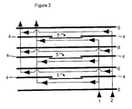
- Figure 2 illustrates a cut away side view of a series of separator plates, PEN cells and frames stacked one on top of another.
- the two separate gas pathways that are to be created are labeled 1 and 2 respectively.
- the separator plates 3 are interspersed between the frames 4, with each frame attached to a PEN cell 5 set inside a frame 4.
- Figure 1 shows a slight gap between the frames 4 and PEN cells 5 for illustrative purposes, in practice, a gas tight seal is formed between the two to prevent any mixing of the gasses.
- the gas pathways 1, 2 shown in Figure 1 represent a "Co-flow" design, meaning simply that the gasses are made to flow in the same direction across the PEN cells.
- the present invention also contemplates “Cross-flow” designs, wherein the gasses are made to flow at some angle (typically 90 degrees) relative to one and another, and “Counter-flow” designs, wherein the gasses are made to flow in opposite directions. Whichever design is selected, the challenge is the same; to stamp the separator plate and the frame in such a way that the separator plate and frame can be sealed to one and another, and two separate gas pathways are formed.
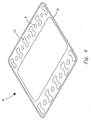
- FIG. 3 and 4 show the separator plate 3 and the frame 4 respectively.
- a raised portion which is displaced upwardly from the surface of the separator plate 3 during the stamping process, and is herein termed the oxygen manifold collar 8 of the separator plate 3 , completely surrounds oxygen manifolds 9 , and also forms the topmost surface of separator plate 3 .
- “upward” “downward” “raised” “lowered” and other such terms are described assuming the separator plate 3 and frame 4 are oriented as shown in Figures 3 and 4 .
- the region 11 of separator plate 3 immediately adjacent to the edge of hydrogen manifolds 9 are displaced in a downward direction during the stamping process, thereby forming a pathway for gasses passing through the hydrogen manifolds to enter this gap between the separator plate 3 and the frame 4 , and to traverse the surface of a PEN cell (shown in Figure 2 ) affixed to frame 4 facing separator plate 3 attached to the bottom of frame 4 .
- a PEN cell shown in Figure 2
- Frame 4 is generally flat, except that the upper edge 6 is displaced to curve in a generally upward direction, such that upper edge 6 is able to form a gas tight seal with the lower edge 7 of separator plate 3 (which are displaced to curve in a downward direction during the stamping process) when separator plate 3 is attached from above frame 4 .
- hydrogen manifold collars 11 (which are displaced in a downward direction during the stamping process) also form a gas tight seal between hydrogen manifold collars 11 and the flat surface of frame 4 .
- This gap forms a pathway for gasses passing through the oxygen manifolds to enter between the separator plate 3 and the frame 4 , and to traverse the surface of a PEN cell (shown in Figure 2 ) affixed to frame 4 facing separator plate 3 attached to the top of frame 4 .
- a PEN cell shown in Figure 2
- FIG. 3 and 4 can be operated as either a co-flow, cross-flow, or counter-flow design, simply by selecting which of the hydrogen and oxygen manifolds 9 , 10 are used to introduce gasses into the stack. While the hydrogen and oxygen manifolds 9 , 10 shown in Figures 3 and 4 are positioned opposite one and another across the surface of the PEN cells, any placement of similar manifolds around the periphery of the PEN cell is possible, and the present invention should in no way be viewed as limited to the specific example selected for illustrative purposes and disclosed in Figures 3 and 4 .
- a separate problem occurs, also as a result of the flexibility of the metals typically used to form the frame and separator plate, in the operation of SOFC stacks formed by the method of the present invention.
- the PEN cells stacked on top of one and another generate electrical power.
- each side of each PEN cell needs to be in electrical contact with the separator plate to link the current generated by each PEN cell in series.
- the inventors have discovered that the flexibility of the materials used to form the separator plate can make it difficult to maintain this electrical contact.
- a solution to this problem is to provide current collectors made from a flexible, electrically conducting material.
- a flexible electrically conducting material is a screen.
- the screen provided on the cathode, or oxidizing side of said separator plate is fabricated from 400 series stainless steel and the screen provided on the anode, or reducing side of said separator plate is fabricated from nickel.
Landscapes
- Chemical & Material Sciences (AREA)
- Life Sciences & Earth Sciences (AREA)
- Engineering & Computer Science (AREA)
- Manufacturing & Machinery (AREA)
- Sustainable Development (AREA)
- Sustainable Energy (AREA)
- Chemical Kinetics & Catalysis (AREA)
- Electrochemistry (AREA)
- General Chemical & Material Sciences (AREA)
- Inorganic Chemistry (AREA)
- Fuel Cell (AREA)
- Inert Electrodes (AREA)
Claims (22)
- Ein Verfahren zum Herstellen einer Kassette für einen Festoxid-Brennstoffzellenstapel, das die Schritte umfasst:a. Stanzen einer Trennplatte (3),b. Stanzen eines Rahmens (4),c. Befestigen einer PEN-Zelle am Rahmen undd. Befestigen des Rahmens an der Trennplatte,dadurch gekennzeichnet, dass das Verfahren aufweist: Ausbilden von Unterstützungserhebungen (14) in der Trennplatte oder dem Rahmen.
- Das Verfahren gemäß Patentanspruch 1, wobei die Trennplatte und der Rahmen aus Edelstahl der 400er Serie gebildet sind.
- Das Verfahren gemäß Patentanspruch 1, das weiterhin umfasst: Bereitstellen von Stromkollektoren, die in Verbindung mit jeder Seite der Trennplatte stehen.
- Das Verfahren gemäß Patentanspruch 3, wobei die Stromkollektoren als ein flexibles elektrisch leitfähiges Material bereitgestellt sind.
- Das Verfahren gemäß Patentanspruch 4, wobei das flexible elektrisch leitfähige Material ein Schirm ist.
- Das Verfahren gemäß Patentanspruch 5, wobei der Schirm, der auf der Kathode oder Oxidationsseite der Trennplatte bereitgestellt ist, aus dem Edelstahl der 400er Serie hergestellt ist.
- Das Verfahren gemäß Patentanspruch 5, wobei der Schirm, der auf der Anode oder Reduktionsseite der Trennplatte bereitgestellt ist, aus Nickel hergestellt ist.
- Ein Verfahren zum Herstellen eines Festoxid-Brennstoffzellenstapels, das die Schritte umfasst:a. Herstellen einer Mehrzahl von Kassetten, die durch das Verfahren gemäß Patentanspruch 1 gebildet sind,b. Stapeln der Mehrzahl von Kassetten aufeinander, sodass die Anodenseite jeder Kassette in elektrischer Verbindung mit der Kathodenseite jeder benachbarten Kassette steht, undc. Ausbilden einer elektrisch isolierenden gasdichten Dichtung zwischen dem Rahmen jeder Kassette und der Trennplatte jeder benachbarten Kassette.
- Das Verfahren gemäß Patentanspruch 8, wobei die elektrisch isolierende gasdichte Dichtung ausgewählt ist aus der Gruppe bestehend aus einem Glas und einer Isolierdichtung.
- Das Verfahren gemäß Patentanspruch 9, wobei die Isolierdichtung Aluminiumoxid ist.
- Das Verfahren gemäß Patentanspruch 10, wobei die Isolierdichtung unter Verwendung einer Hartlötung hermetisch gebunden ist.
- Das Verfahren gemäß Patentanspruch 10, wobei die Isolierdichtung unter Verwendung von Glas hermetisch gebunden ist.
- Eine Kassette für eine Festoxid-Brennstoffzelle, die gemäß des Herstellungsverfahrens gemäß einem der Patentansprüche 1 bis 7 erhältlich ist.
- Eine Festoxid-Brennstoffzelle, die aus einer Mehrzahl von Kassetten gebildet ist, wobei jede Kassette aufweist:a. eine gestanzte Trennplatte (3),b. einen gestanzten Rahmen (4),c. eine PEN-Zelle, die an dem Rahmen angebracht ist, wobei der Rahmen jeder Kassette an der Trennplatte jeder nachfolgenden Kassette in einer gasdichten, nichtleitenden Dichtung befestigt ist, die eine elektrische Isolierung zwischen der Anodenseite und der Kathodenseite jeder PEN-Zelle aufrechterhält,dadurch gekennzeichnet, dass eine oder mehrere Trennplatten oder Rahmen mit Unterstützungserhebungen (14) ausgebildet sind.
- Die Festoxid-Brennstoffzelle gemäß Patentanspruch 14, wobei die elektrisch isolierende gasdichte Dichtung ausgewählt ist aus der Gruppe bestehend aus einem Glas und einer Isolierdichtung.
- Die Festoxid-Brennstoffzelle gemäß Patentanspruch 15, wobei die Isolierdichtung Aluminiumoxid ist.
- Die Festoxid-Brennstoffzelle gemäß Patentanspruch 14, wobei die Trennplatte und der Rahmen aus einem Edelstahl der 400er Serie gebildet sind.
- Die Festoxid-Brennstoffzelle gemäß Patentanspruch 14, die weiterhin Stromkollektoren aufweist, die eine elektrische Verbindung zwischen jeder Seite jeder PEN-Zelle und jeder benachbarten Trennplatte aufrechterhalten.
- Die Festoxid-Brennstoffzelle gemäß Patentanspruch 18, wobei die Stromkollektoren ein flexibles elektrisch leitfähiges Material sind.
- Die Festoxid-Brennstoffzelle gemäß Patentanspruch 19, wobei das flexible elektrisch leitfähige Material ein Schirm ist.
- Die Festoxid-Brennstoffzelle gemäß Patentanspruch 20, wobei der Schirm auf der Kathode oder Oxidationsseite der PEN-Zellen aus Edelstahl der 400er Serie hergestellt ist.
- Die Festoxid-Brennstoffzelle gemäß Patentanspruch 20, wobei der Schirm, der auf der Anode oder Reduktionsseite der PEN-Zellen bereitgestellt ist, aus Nickel hergestellt ist.
Applications Claiming Priority (1)
| Application Number | Priority Date | Filing Date | Title |
|---|---|---|---|
| PCT/US2004/021385 WO2006014155A1 (en) | 2004-07-02 | 2004-07-02 | Solid oxide fuel cell frames and method of manufacture |
Publications (2)
| Publication Number | Publication Date |
|---|---|
| EP1766708A1 EP1766708A1 (de) | 2007-03-28 |
| EP1766708B1 true EP1766708B1 (de) | 2011-12-14 |
Family
ID=34958118
Family Applications (1)
| Application Number | Title | Priority Date | Filing Date |
|---|---|---|---|
| EP04756602A Expired - Lifetime EP1766708B1 (de) | 2004-07-02 | 2004-07-02 | Festoxid-brennstoffzellenrahmen und herstellungsverfahren |
Country Status (6)
| Country | Link |
|---|---|
| EP (1) | EP1766708B1 (de) |
| JP (1) | JP2008505471A (de) |
| AT (1) | ATE537575T1 (de) |
| CA (1) | CA2572496A1 (de) |
| DK (1) | DK1766708T3 (de) |
| WO (1) | WO2006014155A1 (de) |
Families Citing this family (3)
| Publication number | Priority date | Publication date | Assignee | Title |
|---|---|---|---|---|
| US8293426B2 (en) * | 2008-09-30 | 2012-10-23 | Battelle Memorial Institute | Cassettes for solid-oxide fuel cell stacks and methods of making the same |
| CN102714324B (zh) | 2009-07-06 | 2015-03-25 | 托普索燃料电池股份有限公司 | 燃料电池组或电解电池组中组合的流动模式 |
| GB201713141D0 (en) | 2017-08-16 | 2017-09-27 | Ceres Ip Co Ltd | Fuel cell unit |
Family Cites Families (5)
| Publication number | Priority date | Publication date | Assignee | Title |
|---|---|---|---|---|
| US5077148A (en) * | 1989-05-03 | 1991-12-31 | Institute Of Gas Technology | Fully internal manifolded and internal reformed fuel cell stack |
| EP1384280A2 (de) * | 2001-04-27 | 2004-01-28 | Alberta Research Council, Inc. | Durch metallschichten unterstützte elektrochemische festkörperelektrolytzelle und damit versehener mehrzelliger reaktor |
| US20030096147A1 (en) * | 2001-11-21 | 2003-05-22 | Badding Michael E. | Solid oxide fuel cell stack and packet designs |
| US7270906B2 (en) * | 2002-06-24 | 2007-09-18 | Delphi Technologies, Inc. | Solid-oxide fuel cell module for a fuel cell stack |
| JP4087216B2 (ja) * | 2002-10-22 | 2008-05-21 | 東京瓦斯株式会社 | 固体酸化物形燃料電池のシール構造体及びシール方法 |
-
2004
- 2004-07-02 WO PCT/US2004/021385 patent/WO2006014155A1/en not_active Ceased
- 2004-07-02 EP EP04756602A patent/EP1766708B1/de not_active Expired - Lifetime
- 2004-07-02 AT AT04756602T patent/ATE537575T1/de active
- 2004-07-02 JP JP2007520278A patent/JP2008505471A/ja active Pending
- 2004-07-02 CA CA002572496A patent/CA2572496A1/en not_active Abandoned
- 2004-07-02 DK DK04756602.1T patent/DK1766708T3/da active
Also Published As
| Publication number | Publication date |
|---|---|
| WO2006014155A1 (en) | 2006-02-09 |
| DK1766708T3 (da) | 2012-01-23 |
| JP2008505471A (ja) | 2008-02-21 |
| CA2572496A1 (en) | 2006-02-09 |
| EP1766708A1 (de) | 2007-03-28 |
| ATE537575T1 (de) | 2011-12-15 |
Similar Documents
| Publication | Publication Date | Title |
|---|---|---|
| US8288060B2 (en) | Metal-supported solid oxide fuel cell and manufacturing method thereof | |
| JP7194242B1 (ja) | 電気化学反応セルスタック | |
| US7226687B2 (en) | Fuel cell assemblies using metallic bipolar separators | |
| KR20180059518A (ko) | 인터커넥터-전기 화학 반응 단셀 복합체, 전기 화학 반응 셀 스택 및 인터커넥터-전기 화학 반응 단셀 복합체의 제조 방법 | |
| US20040265666A1 (en) | Solid oxide fuel cell frames and method of manufacture | |
| US20050170233A1 (en) | Structurally yieldable fuel cell seal | |
| US10476087B2 (en) | Fuel-cell power generation unit and fuel-cell stack | |
| US7632593B2 (en) | Bipolar plate supported solid oxide fuel cell with a sealed anode compartment | |
| JP7328274B2 (ja) | 燃料電池単セル、燃料電池スタック、および燃料電池単セルの製造方法 | |
| EP1766708A1 (de) | Festoxid-brennstoffzellenrahmen und herstellungsverfahren | |
| US10411274B2 (en) | Arrangement of electrochemical cells and the use of the same | |
| JP7249981B2 (ja) | 電気化学反応セルスタック | |
| US11271221B2 (en) | Electrochemical reaction cell stack, interconnector-electrochemical reaction unit cell composite, and method for manufacturing electrochemical reaction cell stack | |
| JP2017212032A (ja) | 電気化学反応セルスタック | |
| US9123945B2 (en) | Fuel cell with electrolyte electrode assembly projections forming reactant gas channel | |
| KR20070039112A (ko) | 고체 산화물 연료 전지 프레임 및 그 제조방법 | |
| US11233250B2 (en) | Electrochemical reaction unit including cathode-side frame configured to improve spreading of oxidant gas and electrochemical reaction cell stack | |
| KR20220070694A (ko) | 고체산화물 연료전지용 분리판 모듈 및 이를 포함하는 연료전지용 스택 | |
| KR102479821B1 (ko) | 요철 패턴을 갖는 고체산화물 연료전지용 분리판 모듈 및 이를 포함하는 연료전지용 스택 | |
| EP3579319B1 (de) | Elektrochemische reaktionseinheit und elektrochemischer reaktionszellenstapel | |
| JP6827672B2 (ja) | 電気化学反応セルスタック | |
| JP2023119076A (ja) | 複合体 | |
| JP2023080457A (ja) | 電気化学反応単位および電気化学反応セルスタック | |
| JP2023074566A (ja) | 電気化学反応単位および電気化学反応セルスタック | |
| JP2019200879A (ja) | 電気化学反応単位および電気化学反応セルスタック |
Legal Events
| Date | Code | Title | Description |
|---|---|---|---|
| PUAI | Public reference made under article 153(3) epc to a published international application that has entered the european phase |
Free format text: ORIGINAL CODE: 0009012 |
|
| 17P | Request for examination filed |
Effective date: 20070201 |
|
| AK | Designated contracting states |
Kind code of ref document: A1 Designated state(s): AT BE BG CH CY CZ DE DK EE ES FI FR GB GR HU IE IT LI LU MC NL PL PT RO SE SI SK TR |
|
| DAX | Request for extension of the european patent (deleted) | ||
| 17Q | First examination report despatched |
Effective date: 20071005 |
|
| GRAP | Despatch of communication of intention to grant a patent |
Free format text: ORIGINAL CODE: EPIDOSNIGR1 |
|
| GRAS | Grant fee paid |
Free format text: ORIGINAL CODE: EPIDOSNIGR3 |
|
| GRAA | (expected) grant |
Free format text: ORIGINAL CODE: 0009210 |
|
| AK | Designated contracting states |
Kind code of ref document: B1 Designated state(s): AT BE BG CH CY CZ DE DK EE ES FI FR GB GR HU IE IT LI LU MC NL PL PT RO SE SI SK TR |
|
| REG | Reference to a national code |
Ref country code: GB Ref legal event code: FG4D |
|
| REG | Reference to a national code |
Ref country code: CH Ref legal event code: EP |
|
| REG | Reference to a national code |
Ref country code: IE Ref legal event code: FG4D |
|
| REG | Reference to a national code |
Ref country code: DK Ref legal event code: T3 |
|
| REG | Reference to a national code |
Ref country code: DE Ref legal event code: R096 Ref document number: 602004035682 Country of ref document: DE Effective date: 20120223 |
|
| REG | Reference to a national code |
Ref country code: NL Ref legal event code: VDEP Effective date: 20111214 |
|
| PG25 | Lapsed in a contracting state [announced via postgrant information from national office to epo] |
Ref country code: NL Free format text: LAPSE BECAUSE OF FAILURE TO SUBMIT A TRANSLATION OF THE DESCRIPTION OR TO PAY THE FEE WITHIN THE PRESCRIBED TIME-LIMIT Effective date: 20111214 Ref country code: SE Free format text: LAPSE BECAUSE OF FAILURE TO SUBMIT A TRANSLATION OF THE DESCRIPTION OR TO PAY THE FEE WITHIN THE PRESCRIBED TIME-LIMIT Effective date: 20111214 Ref country code: GR Free format text: LAPSE BECAUSE OF FAILURE TO SUBMIT A TRANSLATION OF THE DESCRIPTION OR TO PAY THE FEE WITHIN THE PRESCRIBED TIME-LIMIT Effective date: 20120315 Ref country code: SI Free format text: LAPSE BECAUSE OF FAILURE TO SUBMIT A TRANSLATION OF THE DESCRIPTION OR TO PAY THE FEE WITHIN THE PRESCRIBED TIME-LIMIT Effective date: 20111214 |
|
| PG25 | Lapsed in a contracting state [announced via postgrant information from national office to epo] |
Ref country code: CY Free format text: LAPSE BECAUSE OF FAILURE TO SUBMIT A TRANSLATION OF THE DESCRIPTION OR TO PAY THE FEE WITHIN THE PRESCRIBED TIME-LIMIT Effective date: 20111214 Ref country code: BE Free format text: LAPSE BECAUSE OF FAILURE TO SUBMIT A TRANSLATION OF THE DESCRIPTION OR TO PAY THE FEE WITHIN THE PRESCRIBED TIME-LIMIT Effective date: 20111214 |
|
| PG25 | Lapsed in a contracting state [announced via postgrant information from national office to epo] |
Ref country code: SK Free format text: LAPSE BECAUSE OF FAILURE TO SUBMIT A TRANSLATION OF THE DESCRIPTION OR TO PAY THE FEE WITHIN THE PRESCRIBED TIME-LIMIT Effective date: 20111214 Ref country code: EE Free format text: LAPSE BECAUSE OF FAILURE TO SUBMIT A TRANSLATION OF THE DESCRIPTION OR TO PAY THE FEE WITHIN THE PRESCRIBED TIME-LIMIT Effective date: 20111214 Ref country code: BG Free format text: LAPSE BECAUSE OF FAILURE TO SUBMIT A TRANSLATION OF THE DESCRIPTION OR TO PAY THE FEE WITHIN THE PRESCRIBED TIME-LIMIT Effective date: 20120314 Ref country code: CZ Free format text: LAPSE BECAUSE OF FAILURE TO SUBMIT A TRANSLATION OF THE DESCRIPTION OR TO PAY THE FEE WITHIN THE PRESCRIBED TIME-LIMIT Effective date: 20111214 |
|
| PG25 | Lapsed in a contracting state [announced via postgrant information from national office to epo] |
Ref country code: PL Free format text: LAPSE BECAUSE OF FAILURE TO SUBMIT A TRANSLATION OF THE DESCRIPTION OR TO PAY THE FEE WITHIN THE PRESCRIBED TIME-LIMIT Effective date: 20111214 Ref country code: PT Free format text: LAPSE BECAUSE OF FAILURE TO SUBMIT A TRANSLATION OF THE DESCRIPTION OR TO PAY THE FEE WITHIN THE PRESCRIBED TIME-LIMIT Effective date: 20120416 Ref country code: RO Free format text: LAPSE BECAUSE OF FAILURE TO SUBMIT A TRANSLATION OF THE DESCRIPTION OR TO PAY THE FEE WITHIN THE PRESCRIBED TIME-LIMIT Effective date: 20111214 |
|
| REG | Reference to a national code |
Ref country code: AT Ref legal event code: MK05 Ref document number: 537575 Country of ref document: AT Kind code of ref document: T Effective date: 20111214 |
|
| PLBE | No opposition filed within time limit |
Free format text: ORIGINAL CODE: 0009261 |
|
| STAA | Information on the status of an ep patent application or granted ep patent |
Free format text: STATUS: NO OPPOSITION FILED WITHIN TIME LIMIT |
|
| 26N | No opposition filed |
Effective date: 20120917 |
|
| REG | Reference to a national code |
Ref country code: DE Ref legal event code: R097 Ref document number: 602004035682 Country of ref document: DE Effective date: 20120917 |
|
| PG25 | Lapsed in a contracting state [announced via postgrant information from national office to epo] |
Ref country code: AT Free format text: LAPSE BECAUSE OF FAILURE TO SUBMIT A TRANSLATION OF THE DESCRIPTION OR TO PAY THE FEE WITHIN THE PRESCRIBED TIME-LIMIT Effective date: 20111214 |
|
| PG25 | Lapsed in a contracting state [announced via postgrant information from national office to epo] |
Ref country code: MC Free format text: LAPSE BECAUSE OF NON-PAYMENT OF DUE FEES Effective date: 20120731 |
|
| REG | Reference to a national code |
Ref country code: CH Ref legal event code: PL |
|
| GBPC | Gb: european patent ceased through non-payment of renewal fee |
Effective date: 20120702 |
|
| REG | Reference to a national code |
Ref country code: DK Ref legal event code: EBP |
|
| REG | Reference to a national code |
Ref country code: FR Ref legal event code: ST Effective date: 20130329 |
|
| PG25 | Lapsed in a contracting state [announced via postgrant information from national office to epo] |
Ref country code: DE Free format text: LAPSE BECAUSE OF NON-PAYMENT OF DUE FEES Effective date: 20130201 Ref country code: ES Free format text: LAPSE BECAUSE OF FAILURE TO SUBMIT A TRANSLATION OF THE DESCRIPTION OR TO PAY THE FEE WITHIN THE PRESCRIBED TIME-LIMIT Effective date: 20120325 Ref country code: FR Free format text: LAPSE BECAUSE OF NON-PAYMENT OF DUE FEES Effective date: 20120731 Ref country code: CH Free format text: LAPSE BECAUSE OF NON-PAYMENT OF DUE FEES Effective date: 20120731 Ref country code: GB Free format text: LAPSE BECAUSE OF NON-PAYMENT OF DUE FEES Effective date: 20120702 Ref country code: LI Free format text: LAPSE BECAUSE OF NON-PAYMENT OF DUE FEES Effective date: 20120731 |
|
| REG | Reference to a national code |
Ref country code: IE Ref legal event code: MM4A |
|
| REG | Reference to a national code |
Ref country code: DE Ref legal event code: R119 Ref document number: 602004035682 Country of ref document: DE Effective date: 20130201 |
|
| PG25 | Lapsed in a contracting state [announced via postgrant information from national office to epo] |
Ref country code: IT Free format text: LAPSE BECAUSE OF NON-PAYMENT OF DUE FEES Effective date: 20120702 |
|
| PG25 | Lapsed in a contracting state [announced via postgrant information from national office to epo] |
Ref country code: FI Free format text: LAPSE BECAUSE OF FAILURE TO SUBMIT A TRANSLATION OF THE DESCRIPTION OR TO PAY THE FEE WITHIN THE PRESCRIBED TIME-LIMIT Effective date: 20111214 |
|
| PG25 | Lapsed in a contracting state [announced via postgrant information from national office to epo] |
Ref country code: IE Free format text: LAPSE BECAUSE OF NON-PAYMENT OF DUE FEES Effective date: 20120702 Ref country code: DK Free format text: LAPSE BECAUSE OF NON-PAYMENT OF DUE FEES Effective date: 20120731 |
|
| PG25 | Lapsed in a contracting state [announced via postgrant information from national office to epo] |
Ref country code: TR Free format text: LAPSE BECAUSE OF FAILURE TO SUBMIT A TRANSLATION OF THE DESCRIPTION OR TO PAY THE FEE WITHIN THE PRESCRIBED TIME-LIMIT Effective date: 20111214 |
|
| PG25 | Lapsed in a contracting state [announced via postgrant information from national office to epo] |
Ref country code: LU Free format text: LAPSE BECAUSE OF NON-PAYMENT OF DUE FEES Effective date: 20120702 |
|
| PG25 | Lapsed in a contracting state [announced via postgrant information from national office to epo] |
Ref country code: HU Free format text: LAPSE BECAUSE OF FAILURE TO SUBMIT A TRANSLATION OF THE DESCRIPTION OR TO PAY THE FEE WITHIN THE PRESCRIBED TIME-LIMIT Effective date: 20040702 |