EP1767263A2 - Mikrochip und Verfahren zum Mischen von Flüssigkeiten und Verfahren zur Blutanalyse unter Verwendung eines solchen Mikrochips - Google Patents
Mikrochip und Verfahren zum Mischen von Flüssigkeiten und Verfahren zur Blutanalyse unter Verwendung eines solchen Mikrochips Download PDFInfo
- Publication number
- EP1767263A2 EP1767263A2 EP06020279A EP06020279A EP1767263A2 EP 1767263 A2 EP1767263 A2 EP 1767263A2 EP 06020279 A EP06020279 A EP 06020279A EP 06020279 A EP06020279 A EP 06020279A EP 1767263 A2 EP1767263 A2 EP 1767263A2
- Authority
- EP
- European Patent Office
- Prior art keywords
- flow path
- path portion
- liquid
- kinds
- microchip
- Prior art date
- Legal status (The legal status is an assumption and is not a legal conclusion. Google has not performed a legal analysis and makes no representation as to the accuracy of the status listed.)
- Withdrawn
Links
Images

Classifications
-
- B—PERFORMING OPERATIONS; TRANSPORTING
- B01—PHYSICAL OR CHEMICAL PROCESSES OR APPARATUS IN GENERAL
- B01F—MIXING, e.g. DISSOLVING, EMULSIFYING OR DISPERSING
- B01F25/00—Flow mixers; Mixers for falling materials, e.g. solid particles
- B01F25/40—Static mixers
- B01F25/42—Static mixers in which the mixing is affected by moving the components jointly in changing directions, e.g. in tubes provided with baffles or obstructions
- B01F25/43—Mixing tubes, e.g. wherein the material is moved in a radial or partly reversed direction
- B01F25/433—Mixing tubes wherein the shape of the tube influences the mixing, e.g. mixing tubes with varying cross-section or provided with inwardly extending profiles
- B01F25/4338—Mixers with a succession of converging-diverging cross-sections, i.e. undulating cross-section
-
- B—PERFORMING OPERATIONS; TRANSPORTING
- B01—PHYSICAL OR CHEMICAL PROCESSES OR APPARATUS IN GENERAL
- B01F—MIXING, e.g. DISSOLVING, EMULSIFYING OR DISPERSING
- B01F31/00—Mixers with shaking, oscillating, or vibrating mechanisms
- B01F31/65—Mixers with shaking, oscillating, or vibrating mechanisms the materials to be mixed being directly submitted to a pulsating movement, e.g. by means of an oscillating piston or air column
-
- B—PERFORMING OPERATIONS; TRANSPORTING
- B01—PHYSICAL OR CHEMICAL PROCESSES OR APPARATUS IN GENERAL
- B01F—MIXING, e.g. DISSOLVING, EMULSIFYING OR DISPERSING
- B01F25/00—Flow mixers; Mixers for falling materials, e.g. solid particles
- B01F25/40—Static mixers
- B01F25/42—Static mixers in which the mixing is affected by moving the components jointly in changing directions, e.g. in tubes provided with baffles or obstructions
- B01F25/43—Mixing tubes, e.g. wherein the material is moved in a radial or partly reversed direction
- B01F25/433—Mixing tubes wherein the shape of the tube influences the mixing, e.g. mixing tubes with varying cross-section or provided with inwardly extending profiles
-
- B—PERFORMING OPERATIONS; TRANSPORTING
- B01—PHYSICAL OR CHEMICAL PROCESSES OR APPARATUS IN GENERAL
- B01F—MIXING, e.g. DISSOLVING, EMULSIFYING OR DISPERSING
- B01F33/00—Other mixers; Mixing plants; Combinations of mixers
- B01F33/30—Micromixers
-
- Y—GENERAL TAGGING OF NEW TECHNOLOGICAL DEVELOPMENTS; GENERAL TAGGING OF CROSS-SECTIONAL TECHNOLOGIES SPANNING OVER SEVERAL SECTIONS OF THE IPC; TECHNICAL SUBJECTS COVERED BY FORMER USPC CROSS-REFERENCE ART COLLECTIONS [XRACs] AND DIGESTS
- Y10—TECHNICAL SUBJECTS COVERED BY FORMER USPC
- Y10T—TECHNICAL SUBJECTS COVERED BY FORMER US CLASSIFICATION
- Y10T436/00—Chemistry: analytical and immunological testing
- Y10T436/25—Chemistry: analytical and immunological testing including sample preparation
Definitions
- the present invention relates to a microchip, and to a liquid mixing method and a blood testing method, which use this microchip.
- JP-A-2001-120972 , JP-A-2002-346355 and JP-A-2003-1077 are unsuitable for mixing two kinds of liquid, which differ from each other in viscosity, specific gravity, and content ratio. Also, these methods are unsuitable for mixing liquid solutions in accordance with use intended to perform mixing by continuously sending solutions and to produce a given amount of a mixture of the solutions (that is, produce a certain amount, for example, a total of 20 ⁇ L of the mixture, instead of continuously mixing the solutions). For instance, in the case of mixing a minute amount of blood with a dilute solution in a blood test, the blood and the dilute solution cannot uniformly be mixed by the above methods.
- an object of the invention is to provide a microchip enabled to simply mix given amounts of a plurality of kinds of liquid, which differ in viscosity, specific gravity, and content ratio from one another, and to provide a mixing method using the microchip.
- the microchip according to the invention is configured so that a plurality of kinds of liquid to be mixed is inputted to an inlet port, that atmosphere in the flow path is pressurized or depressurized by connecting a decompression unit to a decompression port, and that the plurality of kinds of liquid inputted to the inlet port is moved together along the flow path.
- a second flow path portion whose cross-sectional area is small
- a first flow path portion whose cross-sectional area is larger than the cross-sectional area of the second flow path portion
- diffusion is performed on the plurality of kinds of liquid due to turbulent.
- the diffusion is performed thereon in the first flow path portions.
- the first flow path portions and the second flow path portions are alternately and continuously formed along the flow path, the plurality of kinds of liquid is gradually mixed with one another. Consequently, the use of a microchip according to the invention enables the uniform mixing of minute amounts of blood and a dilute solution. Additionally, a microchip according to the invention is used in a blood test method, so that the mixing of blood can efficiently and surely be achieved.
- the microchip 10 has a flow path substrate 11.
- an inlet port 12 into which a plurality of kinds of liquid is introduced a flow path 14 adapted to cause the plurality of kinds of liquid to flow while mixing the plurality of kinds of liquid, and a decompression port 13 configured to communicate with the flow path 14.
- a decompression unit adapted to decompress atmosphere in the flow path 14 can be connected to the decompression port 13.
- the decompression of the atmosphere in the flow path 14 by the decompression unit causes the plurality of kinds of liquid preliminarily introduced into the inlet port to flow in the flow path 14 toward the decompression port 13.
- first flow path portions and second flow path portions are alternately formed along a direction (indicated by a dot-dash line designated by "F" in FIG. 1), in which liquid flows.
- the first flow path portions p21, p22, p2.3, p24, p25, p26, p27, and p28 (hereunder generically referred to as a first flow path portion) are configured so that the cross-sectional area of a cross-section perpendicular to a direction, in which liquid flows in the flow path 14, of each of the first flow path portions is larger than the cross-section area of a cross-section perpendicular to this direction of each of flow path portions other than the first flow path portions.
- the second flow path portions p11, p12, p13, p14, p15, p16, p17, p18 and p19 are configured so that the cross-sectional area cf a cross-section perpendicular to a direction, in which liquid flows in the flow path 14, of the second flow path portion is smaller than the cross-section area of a cross-section perpendicular to this direction of the first flow path portion.
- the second flow path portion p11, the first flow path portion p21, the second flow path portion p12, the first flow path portion p22, the second flow path portion p13, the first flow path portion p23, the second flow path portion p14, the first flow path portion p24, the second flow path portion p15, the first flow path portion p25, the second flow path portion p16, the first flow path portion p26, the second flow path portion p17, the first flow path portion p27, the second flow path portion p18, the first flow path portion p28, and the second flow path portion p19 are arranged along a flow direction F, in which liquid flows, in this order and communicate with the inlet port 12.
- a decompression port 13 communicates with the second flow path portion p19.
- first flow path portions and the second flowpath portions formed in the flow path 14 there is no particular limitation to the number of the first flow path portions and the second flowpath portions formed in the flow path 14.
- the flow path 14 is formed substantially like a wave in plan view of the flow path substrate to detour in a direction (designated by an arrow x in FIG. 1) perpendicular to a direction (designated by an arrow y in FIG. 1) from the inlet port 12 to the decompression port 13.
- the shape of the flow path 14 is not limited thereto. The shape of the flow path 14 can appropriately be changed within a range in which the first flow path portion and the second flow path portion can alternately be formed.
- the microchip 10 is manufactured by fabricating a flow path substrate on a surface of a plate with a microdrill.
- the material of the flow path substrate 11 may be either an inorganic material or an organic material.
- the inorganic material used in the flow path substrate 11 are metal, silicon, Teflon (registered tradernark), glass, and ceramics.
- the organic material are a plastic material and a rubber material.
- plastic material examples include COP, PS, PC, PMMA, PE, PET, and PP.
- rubber material examples include a natural rubber, a synthetic rubber, a silicon rubber, and FDMS (polydimethylsiloxane).
- silicon-containing material examples include glass, quartz, amorphous silicon such as silicon wafer, and silicon, such as polymethylsiloxane.
- Particularly preferred examples of the material are PMMA, COP, PS, PC, PET, PDMS, glass, and silicon wafer.
- the flow path 14 may have any shape, for example, a linear shape and a curved shape, a linear shape is preferable.
- the shape of a thick expansion part of the first flow path portion is a hexagon, a circle, a quadrangle, and a polygon. More preferably, the shape of the thick expansion part of the first flow path portion is a hexagon. This facilitates the diffusion of a plurality of kinds of liquid caused to flow. To enhance the flowability of liquid, it is desirable to form the corner portion of the polygon into a chamfered shape.
- the width of a narrow part flow path of the second flow path portion can appropriately be increased or decreased when needed.
- the narrow part flow path of the second flow path portion is a micro-flow-path.
- the "micro-flow-path" is defined to be a flow path whose equivalent diameter is equal to or less than 3mm.
- the equivalent diameter according to the invention is a term generally used in Che field of mechanical engineering.
- this equivalent diameter is equal to the diameter of the circuit tube.
- the equivalent diameter is used to estimate the fluid flow characteristic and the heat transfer characteristic of the pipe according to data representing the equivalent circuit tube.
- the equivalent diameter thereof represents the spatial scale of a phenomenon (representative length thereof).
- deq 2 ⁇ h .
- the details of the equivalent diameter are described in "Mechanical Engineering Dictionary” edited by The Japan Society of Mechanical Engineers (1997), published by Maruzen Co., Ltd.
- the equivalent diameter of the micro-flow-path used according to the invention is 3mm or less, preferably, 10 ⁇ m to 2000 ⁇ m, more preferably, 20 ⁇ m to 1000 ⁇ m.
- the length of the flow path 14 is 1mm to 10000mm, more preferably, 2mm to 100mm.
- the width of the flow path 14 according to the invention is 1 ⁇ m to 3000 ⁇ m, more preferably, 10 ⁇ m to 2000 ⁇ m, further preferably, 50 ⁇ m to 1000 ⁇ m.
- the specimen such as blood
- the width of the flow path 14 is within the above ranges.
- toe cross-sectional area of a cross-section perpendicular to the flow direction F of the first flow path portion is equal to or larger than twice that of a cross-section perpendicular to the flow direction F of the second flow path portion. More preferably, the cross-sectional area of a cross-section perpendicular to the flow direction F of the first flow path portion is equal to or larger chanthrea-times that of a cross-section perpendicular to the flow direction F of the second flow path portion.
- the capacity of the first flow path is equal to or more than 80% of the total capacity of the plurality of kinds of liquid.
- the length in a direction parallel to a direction, in which liquid flows, of the first flow path portion ranges from 0.1 times to ten times the length in a direction parallel to the direction, in which liquid flows, of the second flow path portion.
- a plurality of first and second flow path portions are provided so that the first flow path portion and the second flow path portion are alternately placed.
- the number of the first and second flow path portions ranges from 1 to 100, more preferably, from 3 to 50, furthermore preferably, from 5 to 15.
- a liquid mixing method according to the invention may be performed along a mixing flow path only in one of backward and forward directions of the flow path.
- the liquid mixing method according to the invention may be performed along the flow path in a reciprocating manner.
- a hydrophilisation or hydrophobilization treatment is performed on the inner surface of the flow path 14.
- a hydrophilization treatment is needed.
- a hydrophobilization treatment is needed.
- Conventional surface treatments can be applied as hydrophilization and hydrophobilization treatments.
- the surface treatments are roughly classified into chemical surface treatment methods and physical surface treatment methods.
- Examples of the chemical surface treatment method are chemical treatments, coupling-agent treatments, steaming, graftization, electrochemical treatments, and surface reforming using an addition agent.
- Examples of the physical surface treatment method are UV irradiation methods, electron beam treatments, low temperature plasma treatments, CASING treatments, glow-discharge treatment methods, corona-discharge treatment methods, and oxygen plasma treatments.
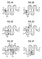
- FIGS. 2A to 2F illustrate a procedure for mixing two kinds of liquid (blood and a dilute solution in this embodiment) using a microchip.
- 0.5 ⁇ l of blood L1 and 25 ⁇ l of the dilute solution L2 are inputted to the inlet port 12.
- the decompression of the flow path is started by a decompression unit (for example, a syringe pump) connected to the decompression port 13.
- the pressurization of the inside of the flow path maybe started by connecting a compression unit (compression means) to the inlet port 12.
- a system of reciprocating the blood L1 and the dilute solution L2 in the flow path may be used.
- the dilute solution L2 which is low in specific gravity and in viscosity, is introduced into the flow path 14, ahead of the blood L1. Subsequently, the blood L1 is introduced into the inside of the flow path. In a case where the expansion and contraction of the cross-section of the flow path 14 are performed, the blood is not mixed with the dilute solution.
- the mixture L3 alternately flows the first flow path portion and the second f low path portion.
- the blood L1 and the dilute solution L2 are further gradually mixed with each other.
- the capacity of the first flow path portion whose cross-sectional area is larger, is substantially equal to or larger than the total capacity of two kinds of liquid to be mixed.
- the capacity of the first flow path portion is substantially equal to or larger than the total capacity of a plurality of kinds of liquid to be mixed.
- the expansion/contraction of the cross-sectional area of the flow path 14 is conducted by performing the increase/reduction of the width dimension of the flow path 14 (dimensions D and d perpendicular to the flow direction F in plan view of the flow path substrate 11).
- the expansion or contraction of the cross-sectional area is gradually performed to prevent the run-out of liquid and the mixing of air bubbles into the liquid.
- the corner portions are chamfered.
- the shape of each part to be expanded or contracted is a triangle.
- a spread angle that is, an angle A shown in FIG. 1 is equal to or less than 90 degrees.
- each chamfered part ranges from (1/10) to (1/2) of the width of the flow path.
- the flow path substrate was manufactured on the surface of a resin plate by a microdrill (see FIG. 1). Subsequently, the flow path substrate was plasma-hydrophilization-treated 15 minutes, together with a PDMS having the same size as that of the flow path substrate. Then, the PDMS plate was mounted on the flow path substrate. The sealed condition of the flow path was established by utilizing a self-adhesive force of the PDMS plate. Thus, the mixing flow path was completed. An inlet port for introducing liquid to be mixed, and a hole having a size suitable for being used as a decompression unit connecting portion (decompression port) thereto were bored in the PDMS plate.
- a multilayer dry slide for analysis of hemoglobin Alc was manufactured. Then, 10 ⁇ l of 50mM glycerophosphate buffer solution containing a known amount of HbAlc in human blood. (pH 7) was trickled onto the slide, which was maintained at 37°C. Subsequently, the reflected optical density was measured with visible light, whose central wavelength was 650nm, by a spectrophotometer (MCPD-2000 manufactured by Otsuka Electronics Co., Ltd.) from the side of a PET support.
- MCPD-2000 manufactured by Otsuka Electronics Co., Ltd.
- the reflected optical density was measured with visible light, whose central wavelength was 650nm, by the spectrophotometer (MCPD-2000 manufactured by Otsuka Electronics Co., Ltd.) from the side of the PET support- Then, the difference ( ⁇ OD 5-3 ) between the reflected optical densities at a moment, at which 3 minutes elapsed since the trickling, and at another moment, at which 5 minutes elapsed since the trickling, was obtained.
- the measured value (g/dL) of hemoglobin Alc was 1.07 ⁇ 0.04.
- a CV was 3.7%.
- a multilayer dry slide for CRP was manufactured according to a method similar to that used in an embodiment; described in JP-A-2003-75445 , Then, 10 ⁇ l of 50mM glycerophosphate buffet solution containing a known amount of CRP in human blood (pH 7) was trickled onto this slide, which was maintained at 37°C. Subsequently, the reflected optical density was measured with visible light, whose central wavelength was 650nm, by a spectrophotometer (MCPD-2000 manufactured by Otsuka Electronics Co., Ltd.) from the side of a PET support.
- MCPD-2000 manufactured by Otsuka Electronics Co., Ltd.
- the reflected optical density was measured with visible light, whose central wavelength was 650nm, by the spectrophotometer (MCPD-2000 manufactured by Otsuka Electronics Co., Ltd.) from the side of the PET support. Then, the difference ( ⁇ OD 5-3 ) between the reflected optical densities at a moment, at which 3 minutes elapsed since the trickling, and at another moment, at which 5 minutes elapsed since the trickling, was obtained.
- the measured value (g/dL) of CRP was 3.00 ⁇ 0.08.
- a CV was 2.7%.
- a pyrophosphoric acid multilayer dry slide for amplification detection was manufactured according to a method similar to that used in an embodiment described in JP-A-2003-61658 . Additionally, 50 ⁇ L of the following reaction liquid was preliminarily inputted to the inlet port. Further, 1 ⁇ L of refined human DNA sample and 1 ⁇ L of distilled water for reference were inputted to a mixture inlet port. Then, the liquid was moved to a temperature cycle part by a decompression unit (for example, a syringe pump) connected to the decompression unit connecting portion of a PDMS.
- a decompression unit for example, a syringe pump
- the optical density of the DNA sample was higher than that of the distilled water. Consequently, it turns out that ALDH genes can be detected.
- the invention can provide a microchip enabled to simply mix given amounts of a plurality of kinds of liquid, which differ in viscosity, specific gravity, and content ratio from one another, and also can provide a mixing method and a blood testing method, each of which use the microchip.
Landscapes
- Chemical & Material Sciences (AREA)
- Chemical Kinetics & Catalysis (AREA)
- Dispersion Chemistry (AREA)
- Automatic Analysis And Handling Materials Therefor (AREA)
- Investigating Or Analysing Biological Materials (AREA)
- Measuring Or Testing Involving Enzymes Or Micro-Organisms (AREA)
Applications Claiming Priority (2)
| Application Number | Priority Date | Filing Date | Title |
|---|---|---|---|
| JP2005279931 | 2005-09-27 | ||
| JP2006257568A JP2007121275A (ja) | 2005-09-27 | 2006-09-22 | マイクロチップ、このマイクロチップを用いた液体の混合方法及び血液検査方法 |
Publications (2)
| Publication Number | Publication Date |
|---|---|
| EP1767263A2 true EP1767263A2 (de) | 2007-03-28 |
| EP1767263A3 EP1767263A3 (de) | 2008-09-17 |
Family
ID=37652333
Family Applications (1)
| Application Number | Title | Priority Date | Filing Date |
|---|---|---|---|
| EP06020279A Withdrawn EP1767263A3 (de) | 2005-09-27 | 2006-09-27 | Mikrochip und Verfahren zum Mischen von Flüssigkeiten und Verfahren zur Blutanalyse unter Verwendung eines solchen Mikrochips |
Country Status (3)
| Country | Link |
|---|---|
| US (1) | US20070077169A1 (de) |
| EP (1) | EP1767263A3 (de) |
| JP (1) | JP2007121275A (de) |
Cited By (2)
| Publication number | Priority date | Publication date | Assignee | Title |
|---|---|---|---|---|
| WO2017175207A1 (en) * | 2016-04-08 | 2017-10-12 | Universidade Do Minho | Modular oscillatory flow plate reactor |
| CN107305210A (zh) * | 2016-04-20 | 2017-10-31 | 光宝电子(广州)有限公司 | 生物检测卡匣及其检测流体的流动方法 |
Families Citing this family (11)
| Publication number | Priority date | Publication date | Assignee | Title |
|---|---|---|---|---|
| US20080080302A1 (en) * | 2006-09-29 | 2008-04-03 | Fujifilm Corporation | Droplet mixing method and apparatus |
| GB0621520D0 (en) * | 2006-10-28 | 2006-12-06 | P2I Ltd | Novel products |
| JP5140386B2 (ja) * | 2007-11-15 | 2013-02-06 | 富士フイルム株式会社 | マイクロ流路内混合方法および装置 |
| JP4985347B2 (ja) * | 2007-11-21 | 2012-07-25 | パナソニック株式会社 | 測定チップ |
| JP5241209B2 (ja) * | 2007-11-26 | 2013-07-17 | 株式会社日立ハイテクノロジーズ | 試料前処理用デバイス及び試料分析方法 |
| US8511889B2 (en) * | 2010-02-08 | 2013-08-20 | Agilent Technologies, Inc. | Flow distribution mixer |
| TWI429484B (zh) * | 2010-12-31 | 2014-03-11 | Resi Corp | 管型連續式反應器以及應用於該反應器之波浪型反應器管 |
| JP6349327B2 (ja) * | 2012-12-17 | 2018-06-27 | レウコドゥックス,リミテッド | 化学的状態を判定するためのシステムおよび方法 |
| TWI584874B (zh) | 2015-06-23 | 2017-06-01 | 台達電子工業股份有限公司 | 管道混合器 |
| WO2020045080A1 (ja) * | 2018-08-31 | 2020-03-05 | 株式会社島津製作所 | 分析装置、分析方法、微量液体採取装置、および微量液体採取方法 |
| CN114452874B (zh) * | 2022-01-27 | 2023-03-28 | 广东省科学院生物与医学工程研究所 | 一种柔性微混合器制备方法 |
Family Cites Families (10)
| Publication number | Priority date | Publication date | Assignee | Title |
|---|---|---|---|---|
| JP3345641B2 (ja) * | 2000-03-10 | 2002-11-18 | 学校法人立命館 | マイクロ分析チップ、及びその製造方法 |
| DE10041823C2 (de) * | 2000-08-25 | 2002-12-19 | Inst Mikrotechnik Mainz Gmbh | Verfahren und statischer Mikrovermischer zum Mischen mindestens zweier Fluide |
| EP1343973B2 (de) * | 2000-11-16 | 2020-09-16 | California Institute Of Technology | Vorrichtung und verfahren zur durchführung von assays und screening mit hohem durchsatz |
| US20030178641A1 (en) * | 2002-01-23 | 2003-09-25 | Blair Steven M. | Microfluidic platforms for use with specific binding assays, specific binding assays that employ microfluidics, and methods |
| DE10204414A1 (de) * | 2002-02-04 | 2003-09-04 | Siemens Ag | Mikrofluidik-System |
| KR100471747B1 (ko) * | 2002-08-23 | 2005-03-16 | 재단법인서울대학교산학협력재단 | 구동에너지 절감을 위한 마이크로 채널구조체 |
| GB0304033D0 (en) * | 2003-02-21 | 2003-03-26 | Imp College Innovations Ltd | Apparatus |
| JP4111505B2 (ja) * | 2003-03-31 | 2008-07-02 | キヤノン株式会社 | 生化学処理装置及び生化学処理方法 |
| US7347617B2 (en) * | 2003-08-19 | 2008-03-25 | Siemens Healthcare Diagnostics Inc. | Mixing in microfluidic devices |
| JP4246642B2 (ja) * | 2004-01-15 | 2009-04-02 | 株式会社日立プラントテクノロジー | マイクロ流体システム |
-
2006
- 2006-09-22 JP JP2006257568A patent/JP2007121275A/ja active Pending
- 2006-09-27 US US11/527,698 patent/US20070077169A1/en not_active Abandoned
- 2006-09-27 EP EP06020279A patent/EP1767263A3/de not_active Withdrawn
Cited By (3)
| Publication number | Priority date | Publication date | Assignee | Title |
|---|---|---|---|---|
| WO2017175207A1 (en) * | 2016-04-08 | 2017-10-12 | Universidade Do Minho | Modular oscillatory flow plate reactor |
| CN107305210A (zh) * | 2016-04-20 | 2017-10-31 | 光宝电子(广州)有限公司 | 生物检测卡匣及其检测流体的流动方法 |
| CN107305210B (zh) * | 2016-04-20 | 2019-09-17 | 光宝电子(广州)有限公司 | 生物检测卡匣及其检测流体的流动方法 |
Also Published As
| Publication number | Publication date |
|---|---|
| EP1767263A3 (de) | 2008-09-17 |
| US20070077169A1 (en) | 2007-04-05 |
| JP2007121275A (ja) | 2007-05-17 |
Similar Documents
| Publication | Publication Date | Title |
|---|---|---|
| EP1943495B1 (de) | Vorrichtung und verfahren zum nachweis von partikeln | |
| US7741130B2 (en) | Fluidic arrays and method of using | |
| EP1767263A2 (de) | Mikrochip und Verfahren zum Mischen von Flüssigkeiten und Verfahren zur Blutanalyse unter Verwendung eines solchen Mikrochips | |
| JP5907979B2 (ja) | 補助チャネルおよびバイパス・チャネルを含むマイクロ流体デバイス | |
| US20070122819A1 (en) | Analyte assay structure in microfluidic chip for quantitative analysis and method for using the same | |
| US8216826B2 (en) | Fluid analyzing apparatus | |
| JP4141494B2 (ja) | マイクロ分析測定装置及びそれを用いたマイクロ分析測定方法 | |
| CN101696916B (zh) | 基于芯片一体化取样探针的液滴分析筛选装置 | |
| JP2007520693A (ja) | 被検体物のマイクロ流体デバイスへの取り込みならびに収納の方法および装置 | |
| US9931630B2 (en) | Autonomous and programmable sequential flow of solutions in capillary microfluidics | |
| AU2016295622B2 (en) | Fluidic system for performing assays | |
| WO2022161424A1 (zh) | 取样装置 | |
| WO2014014911A1 (en) | Point of care testing assay system using novel microfluidics | |
| JP2007155491A (ja) | マイクロリアクターシステム及び送液方法 | |
| US20130130243A1 (en) | Method and device for detecting and quantifying an analyte with recycling of the reagents | |
| CN210752733U (zh) | 一种微流控检测集成芯片 | |
| EP2336776B1 (de) | Flüssigkeitsteststreifen | |
| EP1202057A2 (de) | Trockenfilm-Mikroküvette | |
| Morimoto et al. | Electrochemical microsystem with porous matrix packed-beds for enzyme analysis | |
| EP2348316B1 (de) | Verfahren zum testen einer flüssigkeit | |
| CN117732524A (zh) | 一种微流控芯片 | |
| TW201013182A (en) | Testing strip | |
| CN112023989A (zh) | 一种微流控检测集成芯片及检测样品的方法 | |
| US20250353002A1 (en) | Microfluidic Device For Profiling Biochemical Samples | |
| CN111558403B (zh) | 一种微流控检测芯片及其检测方法 |
Legal Events
| Date | Code | Title | Description |
|---|---|---|---|
| PUAI | Public reference made under article 153(3) epc to a published international application that has entered the european phase |
Free format text: ORIGINAL CODE: 0009012 |
|
| AK | Designated contracting states |
Kind code of ref document: A2 Designated state(s): AT BE BG CH CY CZ DE DK EE ES FI FR GB GR HU IE IS IT LI LT LU LV MC NL PL PT RO SE SI SK TR |
|
| AX | Request for extension of the european patent |
Extension state: AL BA HR MK YU |
|
| PUAL | Search report despatched |
Free format text: ORIGINAL CODE: 0009013 |
|
| AK | Designated contracting states |
Kind code of ref document: A3 Designated state(s): AT BE BG CH CY CZ DE DK EE ES FI FR GB GR HU IE IS IT LI LT LU LV MC NL PL PT RO SE SI SK TR |
|
| AX | Request for extension of the european patent |
Extension state: AL BA HR MK RS |
|
| RIC1 | Information provided on ipc code assigned before grant |
Ipc: G01N 33/49 20060101ALI20080813BHEP Ipc: B01F 5/06 20060101ALI20080813BHEP Ipc: B01F 13/00 20060101AFI20070126BHEP Ipc: B01F 11/00 20060101ALI20080813BHEP |
|
| AKX | Designation fees paid | ||
| STAA | Information on the status of an ep patent application or granted ep patent |
Free format text: STATUS: THE APPLICATION IS DEEMED TO BE WITHDRAWN |
|
| 18D | Application deemed to be withdrawn |
Effective date: 20090318 |
|
| REG | Reference to a national code |
Ref country code: DE Ref legal event code: 8566 |