EP1767362A2 - Dispositif pour accomplir un changement de rouleau ainsi que la machine équipée avec ledit dispositif - Google Patents
Dispositif pour accomplir un changement de rouleau ainsi que la machine équipée avec ledit dispositif Download PDFInfo
- Publication number
- EP1767362A2 EP1767362A2 EP20060019019 EP06019019A EP1767362A2 EP 1767362 A2 EP1767362 A2 EP 1767362A2 EP 20060019019 EP20060019019 EP 20060019019 EP 06019019 A EP06019019 A EP 06019019A EP 1767362 A2 EP1767362 A2 EP 1767362A2
- Authority
- EP
- European Patent Office
- Prior art keywords
- roller
- hubarmstruktur
- sheet
- fed printing
- printing machine
- Prior art date
- Legal status (The legal status is an assumption and is not a legal conclusion. Google has not performed a legal analysis and makes no representation as to the accuracy of the status listed.)
- Withdrawn
Links
- 230000008859 change Effects 0.000 title claims description 21
- 238000003860 storage Methods 0.000 claims abstract description 42
- 238000007639 printing Methods 0.000 claims description 40
- 239000011248 coating agent Substances 0.000 claims description 14
- 238000000576 coating method Methods 0.000 claims description 14
- 239000003973 paint Substances 0.000 claims description 8
- 238000005516 engineering process Methods 0.000 claims description 3
- 230000010354 integration Effects 0.000 claims description 3
- 231100001261 hazardous Toxicity 0.000 claims description 2
- 238000012546 transfer Methods 0.000 description 14
- 238000007774 anilox coating Methods 0.000 description 9
- 238000004140 cleaning Methods 0.000 description 7
- 238000013461 design Methods 0.000 description 7
- 238000013459 approach Methods 0.000 description 5
- 238000000034 method Methods 0.000 description 5
- 230000008569 process Effects 0.000 description 4
- 238000006073 displacement reaction Methods 0.000 description 3
- 238000003780 insertion Methods 0.000 description 3
- 230000037431 insertion Effects 0.000 description 3
- 230000008878 coupling Effects 0.000 description 2
- 238000010168 coupling process Methods 0.000 description 2
- 238000005859 coupling reaction Methods 0.000 description 2
- 238000001514 detection method Methods 0.000 description 2
- 239000004922 lacquer Substances 0.000 description 2
- 238000011144 upstream manufacturing Methods 0.000 description 2
- 230000004913 activation Effects 0.000 description 1
- 230000004888 barrier function Effects 0.000 description 1
- 238000000151 deposition Methods 0.000 description 1
- 238000007606 doctor blade method Methods 0.000 description 1
- 238000000605 extraction Methods 0.000 description 1
- 238000010348 incorporation Methods 0.000 description 1
- 230000000977 initiatory effect Effects 0.000 description 1
- 238000012986 modification Methods 0.000 description 1
- 230000004048 modification Effects 0.000 description 1
- 238000007645 offset printing Methods 0.000 description 1
- 230000003287 optical effect Effects 0.000 description 1
- 210000000056 organ Anatomy 0.000 description 1
- 230000001681 protective effect Effects 0.000 description 1
- 230000001105 regulatory effect Effects 0.000 description 1
- 230000000284 resting effect Effects 0.000 description 1
- 238000009420 retrofitting Methods 0.000 description 1
- 238000005096 rolling process Methods 0.000 description 1
- 238000004904 shortening Methods 0.000 description 1
- 239000006228 supernatant Substances 0.000 description 1
- 230000001360 synchronised effect Effects 0.000 description 1
- 238000001931 thermography Methods 0.000 description 1
- 230000000007 visual effect Effects 0.000 description 1
Images

Classifications
-
- B—PERFORMING OPERATIONS; TRANSPORTING
- B41—PRINTING; LINING MACHINES; TYPEWRITERS; STAMPS
- B41F—PRINTING MACHINES OR PRESSES
- B41F31/00—Inking arrangements or devices
- B41F31/30—Arrangements for tripping, lifting, adjusting, or removing inking rollers; Supports, bearings, or forks therefor
Definitions
- the invention relates to a device for accomplishing a roll change in a paint or coating unit of a sheet-fed printing machine with a lifting device comprising a left Hubarm réelle and a right Hubarm Modell.
- This device serves to displace a roller which can be exchanged into the printing press between a working position and a storage position, in particular for removal or replacement of that roller.
- the invention further relates to a printing machine which is equipped with such a roll changing device.
- Out DE 199 62 425 B4 is a device for changing an anilox roller of a coating unit of a printing press with a Hubarmportal known. About this Hubarmportal an anilox roller can be taken in the region of its working position and initially raised in the vertical direction. Subsequently, the angled roller thus grasped and raised can be displaced in a horizontal direction in a region lying between the side frames of the printing press and deposited on a first or a second storage position adjacent thereto.
- a coating unit for rotary printing presses which is provided with a rotary magazine, in which a plurality of anilox rollers can be stored.
- the rotary magazine is provided with a cable pulling device, via which an anilox roller can be lowered from a downwardly pointing magazine compartment and moved partially manually into a working position.
- a chambered doctor blade coating unit is known, the Includes rotary magazine, in which a plurality of anilox rollers are rotatably mounted.
- the roller bearings of the rotary magazine form the working bearings of the individual chamber rollers.
- By corresponding pivoting of the rotary magazine it is possible to spend each an anilox roller of the same in a working position in which the anilox roller rests on an associated paint form cylinder.
- the invention has for its object to provide solutions which make it possible to accomplish the change of a paint or other removable roller in a sheet-fed or sheet finishing machine in a particularly advantageous manner.
- the storage device for mounting the lifting device on the side frame of the printing machine can be mounted.
- the assembly can be done by a mounting flange, which is preferably designed as such that it can be mounted on standard frame side provided sections, in particular over standard existing fitting and tapped holes.
- the roll changing device can be designed as a largely self-contained assembly, which can also be used later as part of a machine retrofitting in the manner of an "upgrade package" on montagetechnisch advantageous interfaces in the area lying between the side frames.
- the left lifting arm structure and the right lifting arm structure are preferably designed such that the radial distance of the changing roller from the pivot axis is variable.
- the pivot axis is preferably located above the working position of the removable roller.
- the left lift arm structure and the right lift arm structure may be formed so that they are retractable, for lifting out the roller to be changed.
- the left lift arm structure and the right lift arm structure are further extendable radially to the pivot axis to insert the exchange roller in the working position.
- the left and right Hubarminnate may be provided with gripping structures, in particular gripping heads to seize the change roller in the region of the axial ends, in particular bearing journals thereof.
- the left and right Hubarm aged can each form parts of a multi-arm Hubarmsterns.
- This Hubarmstern can comprise two diametrically opposed Hubarm Modellen, so that simultaneous handling of the roller to be inserted and the roller to be replaced is made possible.
- the lifting arm star can also carry other Hubarm Modellen, in particular three, or four arms be formed.
- the control of the roll changing device can be carried out so that at least several phases in a plurality of rollers carried by this and this case, if necessary, also stored.
- the lifting arms are designed according to a particularly preferred embodiment of the invention as a multi-stage telescopic cylinder.
- the telescopic cylinders are connected to the Hubarmstern or the central hub device such that the outer cylinder are in the region of the inner cylinder connection, whereas the piston rods are guided outwardly movable in these outer cylinders.
- the telescopic cylinders can be designed as pressure medium, in particular pressure oil actuated hydraulic cylinder. Alternatively, or in combination with this measure, the telescopic cylinder can also be designed as a spindle, in particular ball screw cylinder.
- the cylinders of a Hubarmsystems are preferably synchronized by means of a synchronization device such that no inadmissible tilting or tilting of the corresponding roller occurs in the context of lifting or lowering.
- the synchronization is preferably realized by mechanical coupling systems such as spindles, link chains, timing belt or handlebars. Alternatively, it is also possible to metrologically detect the stroke state of the roller or the instantaneous radial stroke of the respective arm and make Hubkorrekturen based on regulatory approaches.
- the lifting arms can also be designed as articulated arms, in particular buckling, or scissor articulated arms.
- the buckling can take place within an axial plane which includes the pivot axis of the system. It is also possible, the Hubarm adopted be executed so that the buckling of the lifting arms takes place in each case in a plane radial to the pivot axis of the Hubarmsystems.
- the control of the changing device can be carried out such that at least in phases lifting and pivoting movements are performed superimposed each other.
- the roller grasped by the lifting arm systems can be moved on a path which is optimized with regard to its course.
- the trajectory can be optimized in addition to the consideration of the criterion of collision avoidance, taking into account the mass forces and the time required.
- control technology bewerkstelligbar with less effort, it is possible to operate the system so that initially only each to be handled roller is displaced radially by the cross-arm this cross-arm system relative to the pivot axis and pivoting takes place only when the roller is tightened.
- the initiation of the movements is preferably carried out with a soft start, so that excessive start-up and Abbremsst Kunststoffe be avoided.
- a sheet-fed press On the basis of the above-mentioned inventive concept for a machine-integrated roll changing device, a sheet-fed press is provided.
- This sheet-fed printing machine preferably comprises a bearing device for supporting a changing roller in a working position, wherein the bearing device comprises a roller-clamping device which is selectively engageable in a clamping position and in a release position, wherein in the clamping position, the changing roller is secured in that working position in a rotatably movable manner and can be removed from the storage device in the release position.
- the bearing device can be designed as a backup bearing with unilaterally open receiving shells. Details of this are from the date of the applicant DE 199 62 421 C1 known. It is also possible, the roller and the associated storage or clamping device in such a way that the voltage by axially displaceable Pratzen-, Kochsch-, or otherwise, the respective axial end of the roller bearing engagement structures takes place.
- the lifting arm system can comprise locking and unlocking devices by means of which the clamping device can be actuated.
- the lift arm system may include drive means to rotate the roller in a particular orientation.
- Such an auxiliary drive device can also be integrated into the printing machine as an assembly separate from the lifting arm system.
- roller gripper devices of the Hubarmsysteme can be designed so that they have engagement journal portions which are insertable into a radial opening of the rollers to be changed and temporarily locked therein.
- Such a design of the roller gripper devices is in the date of the applicant DE 199 62 443 C1 described.
- roller gripper devices in such a way that they encompass or grasp the circumference of the roller in the area of axial ends or end pegs.
- the roller can be taken without special consideration of the rotational position thereof.
- the roll change system according to the invention can be designed so that it can be moved between the working position and the storage position by this roller, the web. It is possible, this web-controlled to make a temporary transfer of the roller in an intermediate position in which the roller is accessible to a cleaning device, so that an intermediate cleaning of the roller can be carried out prior to relocation of the same in the storage position. It is also possible to automatically pre-clean the items to be loaded To carry out roll by these brought before moving into the working position in one of the pre-cleaning serving intermediate position and here pre-cleaned, in particular dedusted and cleaned.
- the device according to the invention can be designed such that not only the rollers to be changed but also other functional components of the printing press can be handled by them.
- the device according to the invention can in particular be designed such that it also cleans devices, in particular a cleaning module, or other components of a coating unit, e.g. a chamber doctor device is handled within the printing machine, or e.g. can be moved to a release position.
- a plurality of lifting arms which have different and adapted to the respective hand-to-handle system component gripper or handling heads.
- the storage position may be located in a roll storage area or represent a transfer position upstream of this.
- the roll storage area is preferably located at a location easily accessible to a user in the upper area of the printing press.
- the roll storage area can be located in particular above the upper machine panel.
- a tub device may be provided, in which any media draining from the rollers can be collected.
- a transfer magazine device can be provided in the roll storage area, in which the rolls can be stored in a defined manner and moved in a controlled manner into a position provided for take-up.
- the storage area and the path space accessible to the moving structures can be protected by detection organs, so that, for example, when an intrusion, in particular intervention of a user in the observed area, the issuing of a warning signal or a shutdown of the changing device takes place.
- detection devices can be implemented by incorporating optical means, in particular light barriers, thermal imaging systems or proximity sensors. Instead of a full shutdown of the hazardous Systems can also be switched to an operating mode, for example, the speed of movement of the moving components is lowered, or, for example, provides more sensitive shutdown criteria. It is possible to provide display means by which the user is signaled that he is close, or possibly in an observed area, so that if necessary, the user can still withdraw from the observed area before a safety operating mode of the changing device is controlled.
- the rollers can be equipped with an automatically readable coding or in particular with an optically or otherwise electromagnetically readable data carrier, from which roll-specific information can be read out or possibly also written down.
- a read or write head provided for data transfer can be integrated in the device according to the invention and positioned accordingly.
- the pivot drive of the Hubarmsystems can be designed so that an alternating pivoting or a successive further rotation of the Hubarmsystems done. Activation of the rotary actuator Success preferably program-based according to selectable procedures. It is possible to carry out the control of the changing device from a machine control station. Alternatively, or in combination with this measure, a control from the immediate vicinity of the corresponding printing or coating unit can take place. In particular, in a control from the immediate environment, the individual processes, in particular the pivoting of the Hubarmsystems, lowering or raising the roller in or out of the working position and unlocking the roller tension are performed so slowly that the operator side a visual control of the process and possibly intervention is possible.
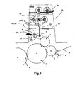
- Figure 1 shows a roll changing device for effecting the change of a here designed as an anilox roll changing roller 1 in a coating unit 2 a sheetfed press.
- the sheet-fed press comprises in a conventional manner a sheet feed table 3, a pre-gripper 4 and a here with a double-sized cylinder 6 cooperating transfer cylinder 5.
- a paint form cylinder 7 On the cylinder 6 runs a paint form cylinder 7.
- the over the paint form cylinder 7 lacquered sheet is from the cylinder. 6 transferred to a drum 8.
- the running direction of the sheet is indicated in Figure 1 by small arrow symbols.
- the chambered scraper device 9 is movably supported by a pivoting mount 10 in such a way that the chambered scraper device 9 can be brought into a release position, as indicated by the arrow symbol P1, in which a subsequent removal or insertion of the exchangeable roller 1 into the working position I is made possible.
- the actual coating unit 2 is located below a cover 11.
- the cover 11 is formed such that it temporarily exposes a window section 12 through which the replacement roller 1 can be moved into the enclosed area or out of it.
- the roll changing device integrated in the printing press 13 comprises a lifting arm device 14 which comprises a left lift arm structure 15 and a right lift arm structure 16 (see FIG. 4).
- the Hubarm annoyed 14 allows a displacement of the removable roller 1 between a working position I and a storage position III.
- the roller changing device further comprises a bearing device 17 for supporting the Hubarm Hughes 14 in a pivotable manner about a pivot axis S, which is aligned substantially parallel to the axis of rotation of the roller 1 to be changed.
- the pivot axis S passes through an intermediate region, which is located in the vertical direction between the working position I and the storage position III of the removable roller.
- the storage device 17 for mounting the Hubarm acknowledged 14 is mounted on the side frame of the printing press 13.
- the left Hubarm réelle 15 and the right Hubarm réelle 16 are formed such that the radial distance of the exchange roller 1 from the pivot axis S is changed by appropriate control of the roll changing device.
- the pivot axis S is located above the working position I of the change roller I. To lift out the change roller 1, the two Hubarm Modellen 15, 16 are retracted, so that the change roller 1, the pivot axis S approaches.
- the Hubarm Medical 15, 16 are pivoted about the pivot axis S, so that the change roller here comes into positions II or IV.
- the changing roller can optionally be treated automatically, in particular cleaned.
- the lifting of the removable roller 1 is carried out by being gripped in the region of its axial ends.
- the Hubarm Geneva 15, 16 are provided for this purpose in the region of its outer ends with gripping structures for gripping the removable roller.
- the Hubarmregalen 15, 16 may form part of a multi-arm Hubarmsterns.
- the Hubarm Profen are executed in the embodiment shown as a telescopic cylinder.
- the sheet-fed printing machine 13 equipped with the aforementioned roll changing device is provided in the region of the bearing point of the exchange roll 1 with a clamping device which can be brought selectively into a clamping position and into a release position.
- a clamping device which can be brought selectively into a clamping position and into a release position.
- the change roller 1 is secured in that working position I in a rotatably movable manner.
- the release position the removable roller 1 can be removed from the associated storage system.
- the storage system can be designed for this purpose as a catch bearing with unilaterally open receiving shells.
- the storage position III is located in an upper roll storage area WAB in which several removable rollers can be stored. It is possible to provide here a magazine device through which the rollers are movable into a Aufgriffswolf suitable for engagement by the Hubarm Modellen 15, 16 Aufgriffswolf.
- the rolls accommodated there are preferably supported in the area of their bearing journals. These journals can hereby rest on both sides vorgesehen bearing tracks 18.
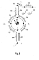
- the roll transfer which can be accomplished within the printing machine by means of the roll changing device according to the invention is illustrated schematically in FIG.
- the Hubarmstern is first pivoted about the pivot axis S such that the provided for lifting the roller 1 Hubarmcru is directed to the roller 1 out. Subsequently, the Hubarmcru is lengthened until the gripper heads of the same engage in corresponding opposite sections of the roller 1. The roller 1 is now unlocked in the area of their bearings, so that it is released for subsequent lifting. In parallel with this, an application device, in particular a chamber doctor device, possibly resting on the roller 1 can be lifted off the roller 1.
- the pair of lifting arms is pivoted in accordance with the arrow T2 so that the roller 1 reaches the position II. In this position, or in an adjacent position, the roller 1 can be supplied to a cleaning device.
- the roller can be released and move in a substantially horizontal direction to a storage position, as indicated by the arrows L1, L2. It is possible to move the roller to a certain storage position by positioning aids or e.g. To support a belt or chain drive, so that the final storage position is achieved positively controlled.
- the roller For automated picking up of a roller from the upper area of the printing press, the roller is first moved to position III. There she is picked up by a Hubarmcru. The now gripped roller is lowered as indicated by the arrow K5, by the lifting arms are retracted.
- the lifting arm system is pivoted (arrow T6) until the roller reaches position IV.
- the roll to be loaded can be pretreated as required, e.g. Dedusted and cleaned.
- the roller is further pivoted (arrow T7) until it reaches the position I '.
- the roller is above the working position I.
- the roller is lowered by expanding the lifting arms in the working position I.
- the receiving mounts provided for receiving the roll end pegs are brought into a receiving state, which allows a sinking of the roll.
- the roll is stored in the receiving warehouse, e.g. tensioned by axial insertion of a locking member.
- a chamber doctor blade device are made to the roller.
- FIG 3 a sketchy a Hubarmsystem is shown, which has only one lift arm 15 (A-side) and 16 (B-side) for each frame side.
- the lifting arm is designed as a telescopic cylinder. It is possible to design and arrange the cylinder so that it passes through the pivot axis S and projects rearwardly beyond the hub region 15N. The supernatant can be dimensioned so that this almost corresponds to the radial distance of the tip of the gripping head 18 of the pivot axis S in the retracted state.
- FIG. 3b shows a two-armed variant of the lifting arm system.
- the lifting arms 15A, 15B are arranged diametrically opposite one another.
- FIG. 3c shows a three-armed variant.
- the lift arms 15A, 15B and 15C are mounted at the same circumferential pitch on the hub portion 15N. It is possible to otherwise define the pitch and thus correlate certain rotational positions of the Hubarmsystems and positions of transfer and possibly treatment stations.
- FIG 3d a three-armed variant is shown.
- the Hubarmsystem can act as an intermediate magazine, in which three rollers can be stored and still a Hubarmcru for lifting the roller from the working position is available.
- FIG. 4 shows in sketch form the position of a Einarmsystems according to Figure 3a within a printing press.
- the A- and B-side frames adjacent lifting arms 15, 16 are connected to each other via a cross-beam 19.
- the cross-beam 19 is designed here as a relatively torsionally rigid structure and extends concentrically to the pivot axis S.
- the cross-beam 19 may also be formed as a bow-like structure, which in this case extends offset on a lifting arms 15, 16 side facing away from the pivot axis.
- a pivot drive via which, for example via a torsion cylinder, a required for pivoting the Hubarmportals drive torque can be applied.
- the device according to the invention is particularly suitable for use in sheet-fed rotary printing presses with flexographic printing or coating units in chamber doctor blade / screen rolling technology. It is also particularly suitable for sheet-fed offset printing presses with upstream, downstream and intermediate lacquer or flexo-works for in-line finishing or pre-coating.
- a machine-integrated handling device (in particular a machine-integrated anilox roller changing machine) which provides component transfer with high dynamics allows.
- the device according to the invention is preferably actuated partially automatically from the control station, either fully automatically or also near the module, possibly under the control of the operator.
- the storage structures provided for incorporation into the printing press are preferably fixed to the side stand fixed to the A and B sides of the printing press.
- the lifting arms can be realized as a telescoping cylinder system extending and retracting vertically.
- the drive of the same is preferably carried out pneumatically.
- the drive of the lift arms can also be hydraulically or otherwise mechanically, e.g. via Kugelgewinde- or parent structures.
- lifting bolts or other catching devices e.g. Ball locking bolt, in particular ball release lock bolts be provided, which engage in the cylinder side provided pin bores and can be locked in this pin bore.
- the disengagement of the balls can be done by pins which are movable in the axial direction within the Aushebebolzens and disengage the associated balls via a shoulder device in the radial direction.
- the engagement of the rollers can also be done by other gripper or hook systems.
- the movement sequence can be protected by protective systems.
- the course of the opening of the machine protection for the passage of the roller can be controlled so that only briefly and only a sufficient opening of the protection takes place.
- the lagklemmung can be automated in terms of process or automatically canceled or caused by special design of the mechanics.
- the rollers can be arranged displaceably.
- a cleaning station alternatively, at least one cleaning trough can be arranged.
- the device according to the invention also makes it possible to handle the change of large rolls by shortening one-man operation by one-man operation.
- the device according to the invention can be adapted to a wide variety of format widths and series with minimal modification requirements. Due to the small space requirement, it can be integrated into existing printing press concepts without changing the side stand contour and changing the lateral machine protection.
Landscapes
- Inking, Control Or Cleaning Of Printing Machines (AREA)
- Replacement Of Web Rolls (AREA)
Applications Claiming Priority (1)
| Application Number | Priority Date | Filing Date | Title |
|---|---|---|---|
| DE200510046088 DE102005046088A1 (de) | 2005-09-27 | 2005-09-27 | Vorrichtung zur Bewerktstlligung eines Walzenwechsels, sowie hiermit ausgestattete Druckmaschine an sich |
Publications (1)
| Publication Number | Publication Date |
|---|---|
| EP1767362A2 true EP1767362A2 (fr) | 2007-03-28 |
Family
ID=37674909
Family Applications (1)
| Application Number | Title | Priority Date | Filing Date |
|---|---|---|---|
| EP20060019019 Withdrawn EP1767362A2 (fr) | 2005-09-27 | 2006-09-12 | Dispositif pour accomplir un changement de rouleau ainsi que la machine équipée avec ledit dispositif |
Country Status (3)
| Country | Link |
|---|---|
| EP (1) | EP1767362A2 (fr) |
| JP (1) | JP2007090881A (fr) |
| DE (1) | DE102005046088A1 (fr) |
Cited By (8)
| Publication number | Priority date | Publication date | Assignee | Title |
|---|---|---|---|---|
| DE102007003975A1 (de) * | 2007-01-26 | 2008-07-31 | Koenig & Bauer Aktiengesellschaft | Druckmaschine in Aggregatbauweise mit in Reihe angeordneten Werken, ausgebildet als Druckwerke und diesen optional zugeordnete Lackwerke |
| DE102019100310A1 (de) * | 2019-01-08 | 2020-07-09 | Koenig & Bauer Ag | Auftragaggregat mit Positioniervorrichtung und Speichereinrichtung |
| DE102019100309A1 (de) * | 2019-01-08 | 2020-07-09 | Koenig & Bauer Ag | Auftragaggregat mit Positioniervorrichtung und Speichereinrichtung |
| WO2020143933A1 (fr) | 2019-01-08 | 2020-07-16 | Koenig & Bauer Ag | Groupe applicateur avec arrangement de positionnement |
| CN112536181A (zh) * | 2020-12-22 | 2021-03-23 | 中冶南方工程技术有限公司 | 卧式辊涂机组及其换辊方法 |
| DE102023127728A1 (de) | 2022-11-14 | 2024-05-16 | Heidelberger Druckmaschinen Aktiengesellschaft | Vorrichtung zum Wechseln von Dosierwalzen in einer Druckmaschine |
| WO2024153504A1 (fr) | 2023-01-17 | 2024-07-25 | Bobst Firenze S.R.L. | Groupe d'impression et procédé pour changer des cylindres d'impression dans un groupe d'impression |
| EP4699810A1 (fr) * | 2024-08-23 | 2026-02-25 | SWISS KRONO Tec AG | Dispositif d'application avec mécanisme d'application |
Families Citing this family (2)
| Publication number | Priority date | Publication date | Assignee | Title |
|---|---|---|---|---|
| KR101118124B1 (ko) * | 2010-05-26 | 2012-03-12 | 한국기계연구원 | 그라비아 옵셋 롤러 자동 교환 장치 |
| JP7004512B2 (ja) * | 2016-12-22 | 2022-01-21 | 株式会社小森コーポレーション | 液体転写装置 |
Citations (5)
| Publication number | Priority date | Publication date | Assignee | Title |
|---|---|---|---|---|
| DE19819389A1 (de) | 1997-07-30 | 1999-02-04 | Heidelberger Druckmasch Ag | Lackierwerk für Rotationsdruckmaschinen |
| DE19962443C1 (de) | 1999-12-22 | 2001-05-03 | Roland Man Druckmasch | Anschlagvorrichtung zum Wechseln eines rotationssymmetrischen Bauteiles in einer Druckmaschine |
| DE19962421C1 (de) | 1999-12-22 | 2001-06-07 | Roland Man Druckmasch | Verfahren und Vorrichtung zum Kuppeln/Entkuppeln eines Zylinders in einer Druckmaschine |
| DE19753136C2 (de) | 1997-11-29 | 2002-01-31 | Koenig & Bauer Ag | Kammerrakel-Lackauftragwerk |
| DE19962425B4 (de) | 1999-12-22 | 2004-01-29 | Man Roland Druckmaschinen Ag | Vorrichtung zum Wechseln eines rotationssymetrischen Bauteiles |
Family Cites Families (2)
| Publication number | Priority date | Publication date | Assignee | Title |
|---|---|---|---|---|
| DE4328058A1 (de) * | 1993-08-20 | 1995-02-23 | Roland Man Druckmasch | Druckmaschine mit mindestens einem auswechselbaren Zylinder, insbesondere einem auswechselbaren Formzylinder, oder mit einer auswechselbaren Druckform |
| DE4413807C1 (de) * | 1994-04-20 | 1995-09-14 | Windmoeller & Hoelscher | Vorrichtung zum Wechseln der Zylinder an einer Druckmaschine |
-
2005
- 2005-09-27 DE DE200510046088 patent/DE102005046088A1/de not_active Withdrawn
-
2006
- 2006-09-12 EP EP20060019019 patent/EP1767362A2/fr not_active Withdrawn
- 2006-09-19 JP JP2006253138A patent/JP2007090881A/ja not_active Withdrawn
Patent Citations (5)
| Publication number | Priority date | Publication date | Assignee | Title |
|---|---|---|---|---|
| DE19819389A1 (de) | 1997-07-30 | 1999-02-04 | Heidelberger Druckmasch Ag | Lackierwerk für Rotationsdruckmaschinen |
| DE19753136C2 (de) | 1997-11-29 | 2002-01-31 | Koenig & Bauer Ag | Kammerrakel-Lackauftragwerk |
| DE19962443C1 (de) | 1999-12-22 | 2001-05-03 | Roland Man Druckmasch | Anschlagvorrichtung zum Wechseln eines rotationssymmetrischen Bauteiles in einer Druckmaschine |
| DE19962421C1 (de) | 1999-12-22 | 2001-06-07 | Roland Man Druckmasch | Verfahren und Vorrichtung zum Kuppeln/Entkuppeln eines Zylinders in einer Druckmaschine |
| DE19962425B4 (de) | 1999-12-22 | 2004-01-29 | Man Roland Druckmaschinen Ag | Vorrichtung zum Wechseln eines rotationssymetrischen Bauteiles |
Cited By (15)
| Publication number | Priority date | Publication date | Assignee | Title |
|---|---|---|---|---|
| DE102007003975B4 (de) | 2007-01-26 | 2021-08-12 | Koenig & Bauer Ag | Druckmaschine in Aggregatbauweise mit in Reihe angeordneten Werken |
| DE102007003975A1 (de) * | 2007-01-26 | 2008-07-31 | Koenig & Bauer Aktiengesellschaft | Druckmaschine in Aggregatbauweise mit in Reihe angeordneten Werken, ausgebildet als Druckwerke und diesen optional zugeordnete Lackwerke |
| US11390068B2 (en) | 2019-01-08 | 2022-07-19 | Koenig & Bauer Ag | Application unit with positioning device and magazine |
| WO2020143932A1 (fr) | 2019-01-08 | 2020-07-16 | Koenig & Bauer Ag | Groupe applicateur avec arrangement de positionnement et dispositif d'accumulation |
| WO2020143931A1 (fr) | 2019-01-08 | 2020-07-16 | Koenig & Bauer Ag | Groupe applicateur avec arrangement de positionnement et dispositif d'accumulation |
| WO2020143933A1 (fr) | 2019-01-08 | 2020-07-16 | Koenig & Bauer Ag | Groupe applicateur avec arrangement de positionnement |
| DE102019100309A1 (de) * | 2019-01-08 | 2020-07-09 | Koenig & Bauer Ag | Auftragaggregat mit Positioniervorrichtung und Speichereinrichtung |
| US11318731B2 (en) | 2019-01-08 | 2022-05-03 | Koenig & Bauer Ag | Application unit with positioning device and magazine |
| DE102019100310A1 (de) * | 2019-01-08 | 2020-07-09 | Koenig & Bauer Ag | Auftragaggregat mit Positioniervorrichtung und Speichereinrichtung |
| CN112536181A (zh) * | 2020-12-22 | 2021-03-23 | 中冶南方工程技术有限公司 | 卧式辊涂机组及其换辊方法 |
| CN112536181B (zh) * | 2020-12-22 | 2024-01-26 | 中冶南方工程技术有限公司 | 卧式辊涂机组及其换辊方法 |
| DE102023127728A1 (de) | 2022-11-14 | 2024-05-16 | Heidelberger Druckmaschinen Aktiengesellschaft | Vorrichtung zum Wechseln von Dosierwalzen in einer Druckmaschine |
| WO2024153504A1 (fr) | 2023-01-17 | 2024-07-25 | Bobst Firenze S.R.L. | Groupe d'impression et procédé pour changer des cylindres d'impression dans un groupe d'impression |
| EP4699810A1 (fr) * | 2024-08-23 | 2026-02-25 | SWISS KRONO Tec AG | Dispositif d'application avec mécanisme d'application |
| WO2026041669A1 (fr) * | 2024-08-23 | 2026-02-26 | SWISS KRONO Tec AG | Appareil d'application comportant un mécanisme d'application |
Also Published As
| Publication number | Publication date |
|---|---|
| DE102005046088A1 (de) | 2007-04-05 |
| JP2007090881A (ja) | 2007-04-12 |
Similar Documents
| Publication | Publication Date | Title |
|---|---|---|
| DE102006032204B3 (de) | Verfahren zur Bereitstellung mindestens einer Druckform an ihrem Montageort auf einem Formzylinder einer Rotationsdruckmaschine | |
| EP0782920B1 (fr) | Contrepoids et mécanisme de levage | |
| EP0788880B1 (fr) | Machine d'impression avec au moins un cylindre imprimeur interchangeable | |
| EP0980312B1 (fr) | Palier pour cylindre de rotative | |
| EP0812681A1 (fr) | Machine d'impression | |
| EP2285572B1 (fr) | Machine a imprimer a mecanismes d'encrage multiples | |
| DE102004037253B4 (de) | Sleevewechselsystem | |
| DE10338373A1 (de) | Vorrichtung zum Wechseln von Druckplatten | |
| DE69025798T2 (de) | Mehrfarbige Flexodruckmaschine mit einer Vorrichtung zum automatischen Auf- und Abladen von Plattenzylindern | |
| DE102011083151B4 (de) | Rotationsdruckmaschine und ein Verfahren zum Austausch zumindest eines ersten Zylinders einer Rotationsdruckmaschine | |
| EP1767362A2 (fr) | Dispositif pour accomplir un changement de rouleau ainsi que la machine équipée avec ledit dispositif | |
| DE10314297B4 (de) | Verfahren und Vorrichtung zum Wechseln mindestens eines Zylinders an einer Druck- oder Lackiermaschine | |
| EP3028782B1 (fr) | Systeme et procede de changement d'outil | |
| EP2296887B1 (fr) | Système et méthode de préhension d'un cylindre de guidage d'encre dans une machine d'impression | |
| EP1366834B1 (fr) | Dispositif de changement d'outil pour presses | |
| DE19962425B4 (de) | Vorrichtung zum Wechseln eines rotationssymetrischen Bauteiles | |
| EP2692455B1 (fr) | Machine-outil pour l'usinage de pièces en forme de plaque, notamment de tôles | |
| DE19856517A1 (de) | Verfahren und Vorrichtung zum Walzenaustausch bei einem Kalander | |
| DE4341854A1 (de) | Anlage zum Kalandrieren | |
| DE4204472C2 (de) | Walzenwechselvorrichtung | |
| EP3946950B1 (fr) | Dispositif et procédé pour remplacer des manchons sur des mandrins de cylindres ou sur des manchons d'adaptation | |
| EP0607541A1 (fr) | Calandre et installation de calandrage | |
| EP1511630B1 (fr) | Remplacement des manchons porte-cliche dans une presse flexo | |
| EP1242243B1 (fr) | Dispositif d'accrochage pour changer un element a symetrie de revolution dans une presse | |
| WO2011015481A1 (fr) | Ensemble comprenant au moins une machine d'impression et un chariot de transport et procédé de transport d'au moins cylindre de la machine d'impression |
Legal Events
| Date | Code | Title | Description |
|---|---|---|---|
| PUAI | Public reference made under article 153(3) epc to a published international application that has entered the european phase |
Free format text: ORIGINAL CODE: 0009012 |
|
| AK | Designated contracting states |
Kind code of ref document: A2 Designated state(s): AT BE BG CH CY CZ DE DK EE ES FI FR GB GR HU IE IS IT LI LT LU LV MC NL PL PT RO SE SI SK TR |
|
| AX | Request for extension of the european patent |
Extension state: AL BA HR MK YU |
|
| RAP1 | Party data changed (applicant data changed or rights of an application transferred) |
Owner name: MANROLAND AG |
|
| STAA | Information on the status of an ep patent application or granted ep patent |
Free format text: STATUS: THE APPLICATION HAS BEEN WITHDRAWN |
|
| 18W | Application withdrawn |
Effective date: 20100922 |