EP1767410A2 - Ceinture de sécurité gonflable et appareil de ceinture de sécurité gonflable - Google Patents
Ceinture de sécurité gonflable et appareil de ceinture de sécurité gonflable Download PDFInfo
- Publication number
- EP1767410A2 EP1767410A2 EP06018109A EP06018109A EP1767410A2 EP 1767410 A2 EP1767410 A2 EP 1767410A2 EP 06018109 A EP06018109 A EP 06018109A EP 06018109 A EP06018109 A EP 06018109A EP 1767410 A2 EP1767410 A2 EP 1767410A2
- Authority
- EP
- European Patent Office
- Prior art keywords
- belt
- bag
- bonding agent
- air belt
- folded back
- Prior art date
- Legal status (The legal status is an assumption and is not a legal conclusion. Google has not performed a legal analysis and makes no representation as to the accuracy of the status listed.)
- Granted
Links
- 239000007767 bonding agent Substances 0.000 claims abstract description 75
- 238000013459 approach Methods 0.000 claims description 4
- 230000003247 decreasing effect Effects 0.000 claims description 4
- 239000000853 adhesive Substances 0.000 abstract description 9
- 150000001875 compounds Chemical class 0.000 abstract description 4
- 238000000034 method Methods 0.000 description 17
- 238000010276 construction Methods 0.000 description 6
- 230000035807 sensation Effects 0.000 description 5
- 239000003795 chemical substances by application Substances 0.000 description 2
- 238000010438 heat treatment Methods 0.000 description 2
- 239000004831 Hot glue Substances 0.000 description 1
- 230000001419 dependent effect Effects 0.000 description 1
- 239000004744 fabric Substances 0.000 description 1
- 238000004519 manufacturing process Methods 0.000 description 1
- 230000002093 peripheral effect Effects 0.000 description 1
- 230000000630 rising effect Effects 0.000 description 1
- 230000035939 shock Effects 0.000 description 1
- 229920001187 thermosetting polymer Polymers 0.000 description 1
Images




Classifications
-
- B—PERFORMING OPERATIONS; TRANSPORTING
- B60—VEHICLES IN GENERAL
- B60R—VEHICLES, VEHICLE FITTINGS, OR VEHICLE PARTS, NOT OTHERWISE PROVIDED FOR
- B60R21/00—Arrangements or fittings on vehicles for protecting or preventing injuries to occupants or pedestrians in case of accidents or other traffic risks
- B60R21/02—Occupant safety arrangements or fittings, e.g. crash pads
- B60R21/16—Inflatable occupant restraints or confinements designed to inflate upon impact or impending impact, e.g. air bags
- B60R21/20—Arrangements for storing inflatable members in their non-use or deflated condition; Arrangement or mounting of air bag modules or components
- B60R21/201—Packaging straps or envelopes for inflatable members
-
- B—PERFORMING OPERATIONS; TRANSPORTING
- B60—VEHICLES IN GENERAL
- B60R—VEHICLES, VEHICLE FITTINGS, OR VEHICLE PARTS, NOT OTHERWISE PROVIDED FOR
- B60R21/00—Arrangements or fittings on vehicles for protecting or preventing injuries to occupants or pedestrians in case of accidents or other traffic risks
- B60R21/02—Occupant safety arrangements or fittings, e.g. crash pads
- B60R21/16—Inflatable occupant restraints or confinements designed to inflate upon impact or impending impact, e.g. air bags
- B60R21/18—Inflatable occupant restraints or confinements designed to inflate upon impact or impending impact, e.g. air bags the inflatable member formed as a belt or harness or combined with a belt or harness arrangement
-
- B—PERFORMING OPERATIONS; TRANSPORTING
- B60—VEHICLES IN GENERAL
- B60R—VEHICLES, VEHICLE FITTINGS, OR VEHICLE PARTS, NOT OTHERWISE PROVIDED FOR
- B60R21/00—Arrangements or fittings on vehicles for protecting or preventing injuries to occupants or pedestrians in case of accidents or other traffic risks
- B60R21/02—Occupant safety arrangements or fittings, e.g. crash pads
- B60R21/16—Inflatable occupant restraints or confinements designed to inflate upon impact or impending impact, e.g. air bags
- B60R21/23—Inflatable members
- B60R21/237—Inflatable members characterised by the way they are folded
Definitions
- the present invention relates to an air belt configured for a bag-shaped belt to be inflated by means of gas supplied from an inflator so as to keep an occupant of a motor vehicle under restraint when the motor vehicle encounters a car crash, or the like, and an air belt apparatus using the same, and more specifically, it relates to an air belt and an air belt apparatus in which a folded back body of the bag-shaped belt is surrounded by a cover, and the folded back body and the cover are bonded with a boding agent.
- air belts are characterized in that an inner surface of the cover is bonded with an outer surface of a folded back body in the air belt including a folded back body formed by folding a bag-shaped belt being inflated to have a belt-like shape by introducing the gas, and an extendable cover that covers the folded back body of the bag-shaped belt.
- bonded portions are provided in a manner of line-like shape being spaced-apart, which are disposed on the folded back body in a longitudinal direction thereof.
- An object of the present invention is to provide an air belt capable of easily distributing a bonding agent composed of an adhesive agent or a cohesive compound in a manner for the bonded part to be uniform, and an air belt apparatus using the same.
- An air belt according to an aspect of the invention is characterized in including a folded back body formed by folding back a bag-shaped belt inflated by means of introducing gas therein, into a belt like shape, and an extendable cover covering the folded back body of the bag-shaped belt, and the air belt is configured so that an inner surface of the cover is bonded to an outer surface of the folded back body with a bonding agent, in which the bonding agent is bonded in a scattered point-like manner.
- the air belt according to a preferred embodiment is characterized in that each of overlapped portions of the bag-shaped belt being folded back is bonded with the bonding agent.
- the air belt according to another preferred embodiment is characterized in that the bonding agent is bonded in the scattered point-like manner on an opposite face of each of the overlapped portions of the bag-shaped belt being folded back.
- the air belt according to a preferred embodiment is characterized in that a distribution density of the bonding agent is partially different.
- the air belt according to still another preferred embodiment is characterized in that an area in the bag-shaped belt being folded back is configured such that the more the number of overlapped portions is, the less the distribution density of the bonding agent is.
- the air belt according to a preferred embodiment is characterized in that the air belt is formed to be a belt-shaped folded back body by folding back for plurality of times along folding back lines in a longitudinal direction thereof so that a width of the bag-shaped belt is decreased from a condition of being flatly extended, and the distribution density of the bonding agent is set to be such that the closer a position in the bag-shaped belt in a flatly extended condition approaches to both end sides in a width direction of the bag-shaped belt, the larger the distribution density of the bonding agent becomes.
- the air belt according to another preferred embodiment is characterized in that the bonding agent has a bonding strength to be released when the folded back body is inflated.
- An air belt apparatus is characterized in including an inflatable air belt, and an inflator for inflating the air belt by supplying gas into the air belt, in which the air belt is the air belt according to any one of the aspect or the preferred embodiments stated above.
- a folded back body of a bag-shaped belt is bonded onto a cover with a scattered point-like bonding agent.
- bonding agent in a scattered point-like manner, bonding portions can be uniformly distributed. Further, the bonding agent can be easily bonded using a roller, or the like.
- the bonding agent is also preferable to be provided in the scattered point-like manner.
- the distribution density of the bonding agent may be partially differed.
- the distribution density of the bonding agent may be set such that the more, the number of overlapped portions in an area are, the less, the distribution density of the bonding agent is.
- the distribution density of the bonding agent may be increased such that the closer a position in the bag-shaped belt in a flatly extended condition approaches to both end sides in a width direction of the bag-shaped belt is, the larger the distribution density of the bonding agent becomes.
- the distribution density i.e., bonding strength
- the bonding is gradually released from the center side in the width direction to the both end sides in the width direction where the distribution density of the bonding agent is relatively large, and the thickness (capacity) of the bag-shaped belt is increasing. Accordingly, it is possible to keep the internal pressure of the bag-shaped belt to be high from a relatively early stage.
- the bonding agent has a bonding strength that releases the bonding in inflating the folded back body, the inflation of the air belt becomes extremely smooth.
- Fig. 1 is a cross-sectional perspective view illustrating an air belt with respect to the embodiment.
- Fig. 2 is a cross-section along a II-II line of Fig. 1.
- the air belt 1 includes a bag-shaped belt 2 that is folded back in an elongate-belt-like shape, and a knit cover 3 serving as a cover that surrounds a folded back body of the bag-shaped belt 2.
- An outer surface of the folded back body and the knit cover 3 are bonded with a bonding agent 4 composed of an adhesive agent or a cohesive compound.
- the bonding agent 4 is provided in a scattered point-like manner.
- a diameter of one point-like formed bonding agent 4 is preferable to be from 2 to 20 mm, and more specifically, it is preferable to be from about 5 to 10 mm, and a distance between each of the closest point-like formed bonding agents 4 is preferable to be from 10 to 50 mm, and more specifically, it is preferable to be from about 10 to 30 mm.
- each of the bag-shaped belts 2 being overlapped together is bonded by means of the bonding agent 4 disposed in the scattered point-like manner, and the shape is kept.
- the knit cover 3 flexibly expands and contracts in a width direction, the knit cover 3 is hardly expanded in a longitudinal direction because a heating-and-stretching process is performed. Accordingly, when a diameter of the knit cover 3 is enlarged at a time of inflation of the air belt 1, the length thereof becomes short. The knit cover 3 bears a tensile load that is applied to the air belt 1.
- the air belt 1 is formed by bonding the folded back body of the bag shaped belt 2 and the knit cover 3 with the bonding agent 4, there is no possibility that the knit cover 3 slides and moves along a surface of the folded back body of the bag-shaped belt 2, and a wearing sensation and a tactile sensation of the air belt 1 is good.
- the bonding agent 4 is provided in the scattered-point manner, a local sliding movement between the bag-shaped belt 2 and the knit cover 3 can also be prevented by increasing the distribution density of the scattered points. The wearing sensation and the tactile sensation of the air belt 1 are thereby remarkably good.
- the adhesive agent is used for the bonding agent 4, for example, a hot melt adhesive agent, a thermosetting adhesive agent, or the like, can be used as the adhesive agent.
- the folded back body of the bag-shaped belt 2 can be kept in a folded back shape (the shape is kept) by heating the bag-shaped belt 2 after folding back the bag-shaped belt 2 upon bonding this kind of adhesive agent onto the bag-shaped belt 2.
- the folded back body of the bag-shaped belt 2 and the knit cover 3 can be bonded by heating the same after surrounding the folded back body, in which the adhesive agent is bonded on the outer surface thereof, with the knit cover 3.
- a roller having a pattern of scattered points may be rolled along the bag-shaped belt 2, or the bonding agent 4 may be supplied from above a template having the pattern of scattered points after overlapping the template on the bag-shaped belt 2.
- the bonding agent 4 may be bonded in the scattered point-like manner by means of the way other than that described above.
- the bonding agent 4 may be bonded on a fabric for manufacturing the bag-shaped belt 2.
- Fig. 3 is a perspective view illustrating an inner part of a room of a motor vehicle provided with an air belt apparatus with respect to the embodiment.
- a seat 21 of the motor vehicle is provided with a seat cushion 22, in which the occupant seats, a seatback 23 constituting a backrest, and a head rest 24 provided at an upper part of the seatback 23.
- the air belt apparatus is provided with an inflatable shoulder belt portion 10 that is diagonally pulled around a front surface side of an upper half of the body of the occupant sitting on the seat 21 (from an upper left to a lower right in this embodiment), a webbing 10a connected to the shoulder belt portion 10, a lap belt portion 11 that is pulled around an upper side of the vicinity of a waist portion of the occupant in a horizontal direction, a buckle apparatus 12 that is provided adjacent to a lateral portion of the seat 21 (right side in this embodiment), a tongue 13 that is inserted into and hooked in the buckle apparatus 12 when the occupant wears the air belt 1, a shoulder anchor 14 for guiding the webbing 10a, retractors, 15 and 16, and the like.
- the aforementioned shoulder belt portion 10 is constituted by the aforementioned air belt 1.
- the webbing 10a is formed of a normal belt similar to the conventional general non-inflation-type seat belt, and is slidably guided and allowed to pass through the shoulder anchor 14. An end portion of the webbing 10a is retractably connected to a seat belt retractor (ELR) 15 having an emergency lock mechanism, which is provided below the shoulder anchor 14.
- ELR seat belt retractor
- One end of the shoulder belt portion 10 is connected to a tip end of the webbing 10a by means of stitching or the like, and the other end thereof is connected to the tongue 13.
- the lap belt portion 11 is formed of a normal belt similar to the general non-inflation-type seat belt, and one end of the lap belt portion 11 is connected to the tongue 13 and the other end of the lap belt portion 11 is retractably connected to a seat belt retractor (ELR) 16 provided at opposite side of the buckle apparatus 12 of the seat 21.
- ELR seat belt retractor
- at least a part of the lap belt portion 11 may be also constituted by the air belt 1.
- an inflator 17 that generates highpressure gas by being activated at a necessary time for emergency such as a car crash, is connected to the buckle apparatus 12, and a nozzle (not shown) for introducing the gas from the inflator 17 to the shoulder belt portion 10 is provided in the tongue 13.
- the gas is introduced into the shoulder belt portion 10 (bag) via the nozzle, and the shoulder belt portion 10 is inflated.
- the aforementioned embodiment is an example of the present invention, and the present invention can take a construction other than that described above.
- the shape of the folded back body of the bag-shaped belt 2 is kept by means of the bonding agent in the aforementioned embodiment, the shape of the folded back body may be kept by means of a tear seam.
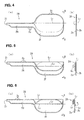
- FIGs. 4(a) through 8(b) are explanatory views explaining a folding back procedure of the bag-shaped belt 2A of the air belt with respect to another embodiment.
- FIGs. 4(a), 5(a), 6(a), 7(a), and 8(a) are side elevations illustrating the bag-shaped belt 2A
- Figs. 4(b), 5(b), 6(b), 7(b), and 8(b) are views looking from a direction indicated by arrows, B and B, of each of Figs. 4(a), 5(a), 6(a), 7(a), and 8(a), respectively.
- Fig. 9 is an exploded perspective view illustrating a distributing condition of the bonding agent for keeping the shape of the bag-shaped belt 2A.
- Fig. 10 is a cross-section along an x-x line of Fig. 8(a).
- a bag-shaped belt 2A of this embodiment is formed to have a relatively thin width from one end side in a longitudinal direction to a middle portion (and at approximately even width in the longitudinal direction), (Hereinbelow, this portion is referred to as thin width portion 2H.) and is formed to have a width thicker than the above, from the middle portion to the other end side (Hereinbelow, this portion is referred to as thick width portion 2F.).
- a gas introducing inlet 2i is provided at a tip end of the thin width portion 2H.
- this bag-shaped belt 2A is formed by overlapping two sheets of panels, 2a and 2b, that respectively constitute each of surfaces of the front surface side and the back surface side (Hereinbelow referred to a front surface side and a back surface side in Fig. 4(a) through Fig. 8(a)) of the bag-shaped belt 2A, and stitching each of the peripheral edge portions thereof together into a bag shape.
- Numeral 2c indicates a stitching seam.
- the thick width portion 2F is formed such that in a condition that the bag-shaped belt 2A is flatly extended while each of the panels, 2a and 2b, are overlapped, one half side and the other half side in the width direction of the bag-shaped belt 2A respectively overhang sideward from both side edges of the thin width portion 2H.
- the overhanging portion of the thick width portion 2F has a shape in which the more the thick width portion overhangs from the side edge of the thin width portion 2H, the smaller the length in a longitudinal direction of the thick width portion 2F becomes.
- the thick width portion 2F is formed to have a plane shape of approximately an ellipse or approximately rectangular shape having four round corners having a width thicker than that of the thin width portion 2H.
- This bag-shaped belt 2A is folded back so as to have the thick width portion 2F having approximately the same thickness as that of the thin width portion 2H.
- a folding back procedure of the bag-shaped belt 2A will be explained.
- the bag-shaped belt 2A is flatly spread in a manner for each of the panels, 2a and 2b to be overlapped, and the one half side in a width direction of the thick width portion 2F (a portion overhanging sideward from a side edge of one side of the thin width potion 2H) is folded back to a front face side of the bag-shaped belt 2A along a folding back line L 1 in the longitudinal direction that is positioned on approximately an extension line of a side edge of one side of the thin width portion 2H.
- Figs. 4(a) and 4(b) the bag-shaped belt 2A is flatly spread in a manner for each of the panels, 2a and 2b to be overlapped, and the one half side in a width direction of the thick width portion 2F (a portion overhanging sideward from a side edge of one side of the thin width potion 2H) is folded back to a front face side of the bag-shaped belt 2A along a folding back line L 1 in the longitudinal direction that is positioned on approximately an extension line of
- one half side of the thick width portion 2F is further folded back to the front side of the bag-shaped belt 2A along a folding back line L 2 in the longitudinal direction that is positioned on approximately an extension line of the other side edge of the thin width portion 2H.
- the folding back operation for the one half side of the thick width portion 2F to the front face side of the bag-shaped belt 2A is repeated for required times until the one half side of the thick width portion 2F does not protrude from both side edges of the thin width portion 2H.
- the other half side of the thick width portion 2F in the width direction (a portion overhanging sideward from the other side edge of the thin width potion 2H) is folded back to a back face side of the bag-shaped belt 2A along a folding back line L 3 in the longitudinal direction that is positioned on approximately an extension line of the side edge of the other side of the thin width portion 2H (a position to be approximately overlapped on the folding back line L 2 ).
- a folding back line L 3 in the longitudinal direction that is positioned on approximately an extension line of the side edge of the other side of the thin width portion 2H (a position to be approximately overlapped on the folding back line L 2 ).
- the other half side of the thick width portion 2F is further folded back to the back face side of the bag-shaped belt 2A along a folding back line L 4 , in the longitudinal direction that is positioned on approximately an extension line of the side edge of the aforementioned one side of the thin width portion 2H (a position to be approximately overlapped on the aforementioned folding back line L 2 ).
- the folding back operation for the other half side of the thick width portion 2F to the back face side of the bag-shaped belt 2A is also repeated for required times until the other half side of the thick width portion 2F does not protrude from both side edges of the thin width portion 2H.
- the bag-shaped belt 2A is formed to be a belt-shaped folded back body having approximately even width for an entire length, as shown in Figs. 8(a) and 8(b).
- the bonding agent 4 is also provided in the scattered point-like manner in-between opposite faces of the thick width portion 2F which is overlapped to each other, and each of the overlapped portions of the thick width portion 2F is bonded by means of the bonding agent 4.
- the mark R 1 in Fig. 9 denotes an area where a total of five portions of a center portion B 1 (a portion between each of the folding lines L 1 and L 3 ) in the width direction of the thick width portion 2F, a portion B 2 between each of the folding lines, L 1 and L 2 , a portion B 3 from the folding back line L 2 to an end portion of the aforementioned one half side of the thick width portion 2F, a portion B 4 between each of folding back lines, L 3 and L 4 , and a portion B 5 from the folding back line L 4 to an end portion of the aforementioned other half side of the thick width portion 2F are overlapped.
- the mark R 2 denotes an area where a total of the aforementioned four portions, B 1 through B 4 , are overlapped.
- the mark R 3 denotes an area where a total of four portions, B 1 , B 2 , B 4 , and B 5 , are overlapped.
- the mark R 4 denotes an area where a total of three portions, B 1 , B 2 , and B 4 , are overlapped.
- the mark R 5 denotes an area where a total of two portions, B 1 and B 2 , are overlapped.
- the mark R 6 denotes an area where a total of two portions, B 1 and B 4 , are overlapped.
- the distribution density of the scattered points of the bonding agent 4 is decreased in the order of the areas, R 5 and R 6 > the area R 4 > the areas, R 2 and R 3 > the area R 1 .
- the distribution density of the bonding agent 4 in each of the areas R 1 through R 6 is adjusted so that hardness (plasticity) of the folded back body of the bag-shaped belt 2A is configured to be approximately even in any one of these areas R 1 through R 6 .
- the air belt 1 is constituted by surrounding the folded back body of the bag-shaped belt 2A with an extendable cover, such as the above-described knit cover 3, or the like.
- an outer surface of the folded back body of the bag-shaped belt 2A and an inner surface of the cover are also bonded by the bonding agent 4 provided in the scattered point-like manner.
- This air belt is also used as the shoulder belt portion 10 of the air belt apparatus shown in Fig. 3.
- the aforementioned gas introducing inlet 2i of the bag-shaped belt 2A is connected to the aforementioned nozzle of the tongue 13.
- Other construction of this air belt apparatus is the same as that of the above-described embodiment.
- This air belt (shoulder belt 10) is worn in a manner so as to be diagonally pulled around a front surface side of the body of the occupant sitting on the seat similar to the case of the normal seat belt.
- the thick width portion 2F of the bag-shaped belt 2A is disposed in sideward portion adjacent to the head portion of the occupant.
- Fig. 11(a) is a side elevation of a folded back body of an air belt with respect to still another embodiment
- Fig. 11(b) is a view looking from a direction indicated by arrows, B and B, in Fig. 11(a)
- Fig. 11(c) is a cross-section (enlarged view) along a C-C line in Fig. 11(a).
- Fig. 12 is a perspective view showing a distribution density of the bonding agent for keeping the shape of the folded back body of the bag-shaped belt.
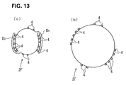
- Figs. 13(a) and 13(b) are cross-sections of the same portion as that in Fig. 11(c) illustrating the bag-shaped belt in the middle of inflation, and on completion of the inflation, respectively.
- the bag-shaped belt 2A in Figs. 11(a) through 13(b) is the same as that in the above-described embodiment illustrated in Figs. 4(a) through 10, and is folded back in the similar folding back procedure as that of the above-described embodiment along the folding back lines, L 1 through L 4 in the longitudinal direction in a manner so as to form the width of the thick width portion 2F to be small.
- each of the overlapped portions of the thick width portion 2F is also bonded by means of the bonding agent 4 provided in a scattered point-like manner at each of the opposite faces thereof.
- the distribution density of the bonding agent 4 at a facing area R 9 is set to be larger than the distribution density of the bonding agent 4 at a facing area R 7 between a center portion (a portion between each of the folding back lines, L 1 and L 3 ) B 1 and the portion B 2 .
- the distribution density of the bonding agent 4 at a facing area R 10 is set to be larger than the distribution density of the bonding agent 4 at a facing area R 8 between the center portion B 1 and the portion B 4 .
- the distribution density of the bonding agent 4 at the areas, R 7 and R 8 is set to be approximately the same.
- the distribution density of the bonding agent 4 at the areas, R 9 and R 10 is set to be approximately the same.
- the distribution density of the bonding agent 4 is set to be such that the closer the position approaches to both end sides from the center side in the width direction of the thick width portion 2F, the larger the distribution density of the bonding agent 4 becomes.
- the internal pressure of the thick width portion 2F is kept high from a relatively early stage, and the thick width portion 2F is inflated earlier.
- the folding back procedure of the bag-shaped belt is not limited to the folding back procedure of each of the above-described embodiment, and the bag-shaped belt may be folded back by means of the procedure other than that described above (for example, a roll folding).
Landscapes
- Engineering & Computer Science (AREA)
- Mechanical Engineering (AREA)
- Air Bags (AREA)
- Seal Device For Vehicle (AREA)
Applications Claiming Priority (1)
| Application Number | Priority Date | Filing Date | Title |
|---|---|---|---|
| JP2005278163A JP4604937B2 (ja) | 2005-09-26 | 2005-09-26 | エアベルト及びエアベルト装置 |
Publications (3)
| Publication Number | Publication Date |
|---|---|
| EP1767410A2 true EP1767410A2 (fr) | 2007-03-28 |
| EP1767410A3 EP1767410A3 (fr) | 2008-04-09 |
| EP1767410B1 EP1767410B1 (fr) | 2010-01-06 |
Family
ID=37526962
Family Applications (1)
| Application Number | Title | Priority Date | Filing Date |
|---|---|---|---|
| EP06018109A Not-in-force EP1767410B1 (fr) | 2005-09-26 | 2006-08-30 | Ceinture de sécurité gonflable et appareil de ceinture de sécurité gonflable |
Country Status (5)
| Country | Link |
|---|---|
| US (1) | US7568726B2 (fr) |
| EP (1) | EP1767410B1 (fr) |
| JP (1) | JP4604937B2 (fr) |
| CN (1) | CN1939780B (fr) |
| DE (1) | DE602006011545D1 (fr) |
Cited By (2)
| Publication number | Priority date | Publication date | Assignee | Title |
|---|---|---|---|---|
| EP2559598A4 (fr) * | 2010-04-12 | 2013-08-21 | Takata Corp | Dispositif de ceinture de sécurité gonflable |
| US11958427B2 (en) * | 2022-07-29 | 2024-04-16 | Hyundai Motor Company | Airbag system |
Families Citing this family (7)
| Publication number | Priority date | Publication date | Assignee | Title |
|---|---|---|---|---|
| JP5446657B2 (ja) * | 2009-09-18 | 2014-03-19 | タカタ株式会社 | エアベルト及びエアベルト装置 |
| JP5254185B2 (ja) * | 2009-11-13 | 2013-08-07 | タカタ株式会社 | エアベルト及びエアベルト装置 |
| JP5803595B2 (ja) * | 2011-11-15 | 2015-11-04 | タカタ株式会社 | エアベルト及びエアベルト装置 |
| ES2489340B1 (es) * | 2013-02-19 | 2015-03-10 | Seat Sa | Cinturón de seguridad |
| JP6294952B2 (ja) * | 2013-03-15 | 2018-03-14 | オートリブ エーエスピー,インコーポレイティド | Icのための二重折りにして巻かれたクッション |
| US9260076B2 (en) * | 2013-07-23 | 2016-02-16 | Honda Motor Co., Ltd. | Method, system and apparatus for stabilizing vehicle occupant's shoulder during side collision impact |
| WO2018215195A1 (fr) | 2017-05-26 | 2018-11-29 | Daimler Ag | Ceinture de sécurité pour un véhicule |
Citations (2)
| Publication number | Priority date | Publication date | Assignee | Title |
|---|---|---|---|---|
| JPH11165603A (ja) | 1997-12-03 | 1999-06-22 | Takata Kk | エアベルト及びエアベルト装置 |
| JPH11255057A (ja) | 1998-03-13 | 1999-09-21 | Honda Motor Co Ltd | エアベルト装置 |
Family Cites Families (7)
| Publication number | Priority date | Publication date | Assignee | Title |
|---|---|---|---|---|
| JP3057116B2 (ja) * | 1991-10-21 | 2000-06-26 | タカタ株式会社 | インフレータブルシートベルト装置 |
| JPH06227347A (ja) * | 1993-02-04 | 1994-08-16 | Kuraray Co Ltd | エアバッグ |
| US5833265A (en) * | 1997-02-21 | 1998-11-10 | Takata, Inc. | Airbag with excursion restrictors |
| JP3900725B2 (ja) * | 1999-01-13 | 2007-04-04 | タカタ株式会社 | エアベルト及びエアベルト装置 |
| JP3899723B2 (ja) * | 1999-03-10 | 2007-03-28 | タカタ株式会社 | エアベルト装置 |
| CN2393903Y (zh) * | 1999-10-26 | 2000-08-30 | 沈阳星辰化工有限公司 | 多点复合防排水卷材 |
| DE102004006843A1 (de) * | 2004-02-11 | 2005-09-01 | Smetan, Herbert, Dipl.-Ing. | Aufblasbarer Sicherheitsgurt |
-
2005
- 2005-09-26 JP JP2005278163A patent/JP4604937B2/ja not_active Expired - Fee Related
-
2006
- 2006-08-30 EP EP06018109A patent/EP1767410B1/fr not_active Not-in-force
- 2006-08-30 DE DE602006011545T patent/DE602006011545D1/de active Active
- 2006-09-20 CN CN200610138953XA patent/CN1939780B/zh not_active Expired - Fee Related
- 2006-09-25 US US11/526,008 patent/US7568726B2/en not_active Expired - Fee Related
Patent Citations (2)
| Publication number | Priority date | Publication date | Assignee | Title |
|---|---|---|---|---|
| JPH11165603A (ja) | 1997-12-03 | 1999-06-22 | Takata Kk | エアベルト及びエアベルト装置 |
| JPH11255057A (ja) | 1998-03-13 | 1999-09-21 | Honda Motor Co Ltd | エアベルト装置 |
Cited By (3)
| Publication number | Priority date | Publication date | Assignee | Title |
|---|---|---|---|---|
| EP2559598A4 (fr) * | 2010-04-12 | 2013-08-21 | Takata Corp | Dispositif de ceinture de sécurité gonflable |
| US8657332B2 (en) | 2010-04-12 | 2014-02-25 | Takata Corporation | Air belt apparatus |
| US11958427B2 (en) * | 2022-07-29 | 2024-04-16 | Hyundai Motor Company | Airbag system |
Also Published As
| Publication number | Publication date |
|---|---|
| EP1767410A3 (fr) | 2008-04-09 |
| US7568726B2 (en) | 2009-08-04 |
| JP2007083996A (ja) | 2007-04-05 |
| CN1939780B (zh) | 2010-12-01 |
| CN1939780A (zh) | 2007-04-04 |
| EP1767410B1 (fr) | 2010-01-06 |
| JP4604937B2 (ja) | 2011-01-05 |
| DE602006011545D1 (de) | 2010-02-25 |
| US20070069509A1 (en) | 2007-03-29 |
Similar Documents
| Publication | Publication Date | Title |
|---|---|---|
| US9598042B2 (en) | Safety restraint system with inflatable pelvis restraint device | |
| US7322603B2 (en) | Seat belt system including an airbag | |
| EP2559598B1 (fr) | Dispositif de ceinture de securite gonflable | |
| EP2047764B1 (fr) | Agencement boucle-languette pour système de ceinture de sécurité | |
| US11981282B2 (en) | Airbag device and vehicle seat | |
| EP1767410B1 (fr) | Ceinture de sécurité gonflable et appareil de ceinture de sécurité gonflable | |
| US7484755B2 (en) | Air belt and air belt apparatus | |
| EP1743810A1 (fr) | Ceinture et système de retenue pour les occupants d'un véhicule | |
| EP1927517A1 (fr) | Dispositif de retenue des occupants d'un vehicule | |
| JP6175012B2 (ja) | シートベルト装置の製造方法 | |
| JP2014196014A (ja) | 側面衝突用乗員保護装置 | |
| EP1738969A2 (fr) | Ceinture de retenue d'un occupant et système de retenue de cet occupant | |
| US20160297389A1 (en) | Seatbelt device | |
| US6402194B1 (en) | Air belt and air belt assembly | |
| EP0964087B1 (fr) | Fabrication d'un sac pour une ceinture de sécurité gonflable, et ceinture de sécurité | |
| CN108725377A (zh) | 用于车辆的空气安全带装置 | |
| JP4165217B2 (ja) | 乗員保護装置 | |
| US7789420B2 (en) | Occupant restraint apparatus | |
| US20060237954A1 (en) | Air belt | |
| EP1939050A1 (fr) | Dispositif de retenue des occupants d'un véhicule | |
| JP2009154743A (ja) | エアバッグ装置 |
Legal Events
| Date | Code | Title | Description |
|---|---|---|---|
| PUAI | Public reference made under article 153(3) epc to a published international application that has entered the european phase |
Free format text: ORIGINAL CODE: 0009012 |
|
| AK | Designated contracting states |
Kind code of ref document: A2 Designated state(s): AT BE BG CH CY CZ DE DK EE ES FI FR GB GR HU IE IS IT LI LT LU LV MC NL PL PT RO SE SI SK TR |
|
| AX | Request for extension of the european patent |
Extension state: AL BA HR MK YU |
|
| PUAL | Search report despatched |
Free format text: ORIGINAL CODE: 0009013 |
|
| AK | Designated contracting states |
Kind code of ref document: A3 Designated state(s): AT BE BG CH CY CZ DE DK EE ES FI FR GB GR HU IE IS IT LI LT LU LV MC NL PL PT RO SE SI SK TR |
|
| AX | Request for extension of the european patent |
Extension state: AL BA HR MK RS |
|
| 17P | Request for examination filed |
Effective date: 20080911 |
|
| 17Q | First examination report despatched |
Effective date: 20081114 |
|
| AKX | Designation fees paid |
Designated state(s): DE GB |
|
| GRAP | Despatch of communication of intention to grant a patent |
Free format text: ORIGINAL CODE: EPIDOSNIGR1 |
|
| GRAS | Grant fee paid |
Free format text: ORIGINAL CODE: EPIDOSNIGR3 |
|
| GRAA | (expected) grant |
Free format text: ORIGINAL CODE: 0009210 |
|
| AK | Designated contracting states |
Kind code of ref document: B1 Designated state(s): DE GB |
|
| REG | Reference to a national code |
Ref country code: GB Ref legal event code: FG4D |
|
| REF | Corresponds to: |
Ref document number: 602006011545 Country of ref document: DE Date of ref document: 20100225 Kind code of ref document: P |
|
| PLBE | No opposition filed within time limit |
Free format text: ORIGINAL CODE: 0009261 |
|
| STAA | Information on the status of an ep patent application or granted ep patent |
Free format text: STATUS: NO OPPOSITION FILED WITHIN TIME LIMIT |
|
| 26N | No opposition filed |
Effective date: 20101007 |
|
| PGFP | Annual fee paid to national office [announced via postgrant information from national office to epo] |
Ref country code: DE Payment date: 20130829 Year of fee payment: 8 |
|
| PGFP | Annual fee paid to national office [announced via postgrant information from national office to epo] |
Ref country code: GB Payment date: 20130828 Year of fee payment: 8 |
|
| REG | Reference to a national code |
Ref country code: DE Ref legal event code: R119 Ref document number: 602006011545 Country of ref document: DE |
|
| GBPC | Gb: european patent ceased through non-payment of renewal fee |
Effective date: 20140830 |
|
| REG | Reference to a national code |
Ref country code: DE Ref legal event code: R119 Ref document number: 602006011545 Country of ref document: DE Effective date: 20150303 |
|
| PG25 | Lapsed in a contracting state [announced via postgrant information from national office to epo] |
Ref country code: DE Free format text: LAPSE BECAUSE OF NON-PAYMENT OF DUE FEES Effective date: 20150303 Ref country code: GB Free format text: LAPSE BECAUSE OF NON-PAYMENT OF DUE FEES Effective date: 20140830 |