EP1767734A2 - Liaison articulée et charnière à articulations multiples avec une telle liaison articulée - Google Patents
Liaison articulée et charnière à articulations multiples avec une telle liaison articulée Download PDFInfo
- Publication number
- EP1767734A2 EP1767734A2 EP06017308A EP06017308A EP1767734A2 EP 1767734 A2 EP1767734 A2 EP 1767734A2 EP 06017308 A EP06017308 A EP 06017308A EP 06017308 A EP06017308 A EP 06017308A EP 1767734 A2 EP1767734 A2 EP 1767734A2
- Authority
- EP
- European Patent Office
- Prior art keywords
- articulated
- articulated arm
- eccentric sleeve
- hinge
- bolt
- Prior art date
- Legal status (The legal status is an assumption and is not a legal conclusion. Google has not performed a legal analysis and makes no representation as to the accuracy of the status listed.)
- Withdrawn
Links
Images





Classifications
-
- E—FIXED CONSTRUCTIONS
- E05—LOCKS; KEYS; WINDOW OR DOOR FITTINGS; SAFES
- E05D—HINGES OR SUSPENSION DEVICES FOR DOORS, WINDOWS OR WINGS
- E05D3/00—Hinges with pins
- E05D3/06—Hinges with pins with two or more pins
- E05D3/14—Hinges with pins with two or more pins with four parallel pins and two arms
- E05D3/145—Hinges with pins with two or more pins with four parallel pins and two arms specially adapted for vehicles
-
- E—FIXED CONSTRUCTIONS
- E05—LOCKS; KEYS; WINDOW OR DOOR FITTINGS; SAFES
- E05D—HINGES OR SUSPENSION DEVICES FOR DOORS, WINDOWS OR WINGS
- E05D7/00—Hinges or pivots of special construction
- E05D7/0009—Adjustable hinges
- E05D7/0018—Adjustable hinges at the hinge axis
- E05D7/0045—Adjustable hinges at the hinge axis in a radial direction
- E05D7/0054—Adjustable hinges at the hinge axis in a radial direction by means of eccentric parts
-
- E—FIXED CONSTRUCTIONS
- E05—LOCKS; KEYS; WINDOW OR DOOR FITTINGS; SAFES
- E05Y—INDEXING SCHEME ASSOCIATED WITH SUBCLASSES E05D AND E05F, RELATING TO CONSTRUCTION ELEMENTS, ELECTRIC CONTROL, POWER SUPPLY, POWER SIGNAL OR TRANSMISSION, USER INTERFACES, MOUNTING OR COUPLING, DETAILS, ACCESSORIES, AUXILIARY OPERATIONS NOT OTHERWISE PROVIDED FOR, APPLICATION THEREOF
- E05Y2800/00—Details, accessories and auxiliary operations not otherwise provided for
- E05Y2800/26—Form or shape
- E05Y2800/31—Form or shape eccentric
Definitions
- the invention relates to a joint with a first and a second articulated arm, which are pivotable about a common hinge axis, wherein an axial position of at least one articulated arm is adjustable relative to the hinge axis by means of an eccentric element.
- the invention further relates to a multi-joint hinge with such a hinge connection.
- a multi-joint hinge with such a hinge connection is, for example, from DE 92 03 856.5 known:
- the multi-joint hinge comprises four articulated arms: two stop elements and a coupling member and a control member, these four articulated arms are each formed from a flat material portion.
- the control member is connected to a stop element via a rivet bolt, which is freely rotatably mounted with a subsequent to a head portion cylindrical shaft portion in a recess of the stop element with the interposition of a bearing bush.
- a hinge pin engaging in an associated eye bore of the control member is arranged eccentrically to the axis of the shaft part. The connection of the control member to the stop member is ensured by riveting the free end of the hinge pin against the outer surface of the control member.
- a disadvantage of such a hinge connection is that the hinge pin has along its longitudinal direction an eccentric portion, over which the axial position of the control member is adjustable relative to the stop element. This eccentric portion leads to high frictional forces and an asymmetric force attack on the hinge pin when the hinge pin is rotated by the rivet connection, as a result of which the hinge pin is subject to high wear. Since the hinge pin is rotatable only by applying large torques, this can be difficult to rotate by means of a slot-shaped tool attachment at one end of the hinge pin.
- the object of the invention is therefore to provide an improved articulated joint and a multi-joint hinge with this improved articulated joint, in which the eccentric element is loaded symmetrically and is easier to rotate.
- This object is achieved in a generic articulated joint in that on the first articulated arm a hinge axis forming bolt is attached and the second articulated arm in a joint opening an eccentric forming the eccentric sleeve, wherein the second articulated arm and the eccentric sleeve on a releasable mechanical connection to the Bolts are held.
- a sliding bearing between the second articulated arm and the eccentric sleeve is provided in the joint opening.
- the bolt is advantageously attached to a mounting end by riveting or welding to the first articulated arm.
- a thread is formed at an end opposite the attachment end of the bolt, and a fastening nut on the thread, the second articulated arm and the eccentric sleeve on the bolt holding screwed.
- the eccentric sleeve has a radial projection, via which the fastening nut holds the second articulated arm on the bolt.
- the eccentric sleeve has means for interacting with an adjusting tool, so that the eccentric sleeve is rotatable about the bolt by means of the adjusting tool.
- the eccentric sleeve in the assembled state via locking means in different predetermined Rat einen relative to an articulated arm can be fixed.
- the detent positions are assigned a scale on one of the articulated arms, resulting in an angular position of the eccentric sleeve or a radial offset of the first articulated arm to the second articulated arm.
- the first articulated arm of the bolt comprises radially extending, about the bolt and offset by a predetermined angle arranged insertion into which at least one locking lug formed on the eccentric sleeve can be inserted, whereby the latching means is formed.
- Adjacent insertion openings may be offset by a same or a varying angle.
- a multi-link hinge according to claim 11 has at least one such articulated connection.
- a multi-joint hinge may have four or seven articulated arms.
- a multi-joint hinge advantageously has two joint connections according to the invention.
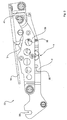
- a multi-joint hinge 33 in FIGS. 1 to 3 has a first 3, a second 5, a third 39 and a fourth 41 articulated arm, wherein an articulated connection 1 according to the invention is arranged between the first 3 and the second articulated arm 5.
- the first articulated arm 3 has three elongated holes 35, which serve for fastening the multi-joint hinge 33 on a side wall of a trunk of a motor vehicle, in particular a passenger car.
- the fourth articulated arm 41 has a mounting surface 37 for fastening a boot lid.
- a multi-joint hinge 33 is arranged in each case, so that the trunk lid can be pivoted by two multi-joint hinges 33 between an open and a closed position.
- a bolt 11 is inserted into the first articulated arm 3.
- the bolt 11 has a rivet head 19 at a fastening end 17, which serves to produce a riveted joint between the bolt 11 and the first articulated arm 3.
- a thread 21 is formed at a the rivet head 19 opposite end of the bolt 11.
- FIG. 5 shows the riveted connection between the bolt 11 and the first articulated arm 3.
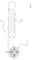
- the bolt 11 is inserted through a hinge opening 12 in the second articulated arm 5, wherein in the joint opening 12, a sliding bearing 15 is arranged.
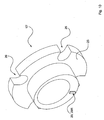
- an eccentric sleeve 13 is arranged, which is shown in Figure 7 in a perspective view.
- Figure 9 also shows in a plan view a center offset d between an inner bore through which the bolt 11 is inserted, and an outer periphery on which the sliding bearing 15 is applied.
- the eccentric sleeve 13 has a radial projection 25, with which it rests on the sliding bearing 15 eccentric sleeve 13.
- a fastening nut 23 is screwed onto the thread 21 of the bolt 11, whereby the eccentric sleeve 13 is pressed against the first articulated arm 3.
- the second articulated arm 5 is pivotable about the eccentric sleeve 13 and thus about the articulation axis 7 by means of the sliding bearing 15.
- the eccentric sleeve 13 has slot-shaped recesses 26, as shown in Figure 7, which serve to cooperate with an adjusting tool 27, which is shown in Figure 8.
- FIG. 9 shows the interaction between the adjusting tool 27 and the eccentric sleeve 13.
- the adjusting tool 27 can be gripped on a handle 28 and the eccentric sleeve 13 are rotated in the plane of Figure 9 in one or the other direction.
- the first and second articulated arm 3, 5 are pivotable about the common hinge axis 7, which forms the pin 11.
- the fastening nut 23 is released so far that the eccentric sleeve 13 can be rotated.
- the adjusting tool 27 is brought into engagement with the eccentric sleeve 13 and this rotated by a certain angle about the hinge axis 7 until the desired axial position of the second articulated arm 5 is achieved relative to the first articulated arm 3.
- the adjusting tool 27 is released from the eccentric sleeve 13 and the fastening nut 23 is tightened to fix the eccentric sleeve 13 again.
- hinge joint 1 is described in an alternative embodiment 13 ', 3', 5 ':
- the eccentric sleeve 13 'in Figure 10 is substantially identical to the eccentric sleeve 13, except for the difference that the eccentric sleeve 13' in contrast to the eccentric sleeve 13 has a latching nose 29 R on one of the projection 25 opposite end.
- the first articulated arm 3 'shown in Fig. 11 is substantially identical to the first articulated arm 3, except that the first articulated arm 3' has insertion holes 29E disposed around the pin 11, with adjacent insertion holes 29E have an equal angular distance from each other.
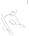
- the second articulated arm 5 ' which is shown in Fig. 12, is substantially identical in construction to the second articulated arm 5, with the difference that on the second articulated arm 5 ', a scale 31 is arranged in a circular arc around the joint opening 12.
- the locking lug 29R is formed to fit the insertion openings 29E, so that the eccentric sleeve 13 'can be arranged in the positions predetermined by the insertion openings 29E on the first articulated arm 3' and fastened by the fastening nut 23.
- the scale 31 on the second articulated arm 5 ' indicates the direction of a radial offset of the first articulated arm 3' relative to the second articulated arm 5 'on the protrusion 25 in conjunction with a mark, not shown.
- the insertion openings 29E and the latching lug 29R thus form a latching means 29, which determines the eccentric sleeve 13 in predetermined locking positions relative to the first articulated arm 3 '.
- the multi-joint hinge 33 of Figures 1 to 3 may comprise a plurality of joint connections according to the invention.
- the trunk lid in the direction of travel of the motor vehicle or perpendicular thereto is displaced or adjustable. In this way, a gap of the boot lid is adjustable.
- the articulated connection 1 is preferably provided on a first articulation axis, by means of which the trunk lid can be displaced along the direction of travel of the motor vehicle, and on a second articulation axis, by means of which the trunk lid can be displaced perpendicular to the direction of travel of the motor vehicle.
- the articulated joints 1 can be provided on adjacent or diagonally opposite hinge axes.
- the boot lid along any desired direction in the closed position can be adjusted without an adjustment of the position of the multi-joint hinges 33 must be made relative to the side walls of the trunk by means of slots 35.
- the first articulated arm 3 may thus have three simple round holes instead of the three slots 35, via which the multi-joint hinge 33 is attached to the side wall of the trunk.
- a slight change in the position of the multi-joint hinges 33 as a whole relative to the side walls of the trunk by means of the slots 35 for setting a desired position of the boot lid is then no longer necessary, since these changes can be made by the eccentric sleeves 13.
- the gap dimension of a boot lid is adjustable in a simple and fast manner, since the multi-joint hinge does not have to be changed as a whole in its position. This is particularly advantageous when the body is painted with the multi-joint hinge and the boot lid, since then the multi-joint hinge no longer needs to be adjusted to the side wall of the trunk when the boot lid occupies an undesirable relative position to the body.
- a water channel of the trunk can thereby be arranged higher because no clearance for a movement of the multi-joint hinge 33 along a vertical downward direction must be provided.
- the bolt 11 is fastened to the first articulated arm 3 via a riveted connection.
- the bolt 11 may be screwed into the first articulated arm 3.
- a pin can be inserted through a section of the bolt 11 ("riveting end 19") lying to the left of the first articulated arm 3 in FIG.
- a nut is screwed onto the section of the bolt 11 ("rivet end") lying to the left of the first articulated arm 3 in FIG. 4 in order to fasten the bolt 11 to the first articulated arm 3.
Landscapes
- Engineering & Computer Science (AREA)
- Mechanical Engineering (AREA)
- Hinges (AREA)
- Pivots And Pivotal Connections (AREA)
- Superstructure Of Vehicle (AREA)
Applications Claiming Priority (1)
| Application Number | Priority Date | Filing Date | Title |
|---|---|---|---|
| DE102005045966A DE102005045966B4 (de) | 2005-09-26 | 2005-09-26 | Gelenkverbindung und Mehrgelenkscharnier mit einer Gelenkverbindung |
Publications (2)
| Publication Number | Publication Date |
|---|---|
| EP1767734A2 true EP1767734A2 (fr) | 2007-03-28 |
| EP1767734A3 EP1767734A3 (fr) | 2013-03-13 |
Family
ID=37499238
Family Applications (1)
| Application Number | Title | Priority Date | Filing Date |
|---|---|---|---|
| EP06017308A Withdrawn EP1767734A3 (fr) | 2005-09-26 | 2006-08-19 | Liaison articulée et charnière à articulations multiples avec une telle liaison articulée |
Country Status (2)
| Country | Link |
|---|---|
| EP (1) | EP1767734A3 (fr) |
| DE (1) | DE102005045966B4 (fr) |
Cited By (2)
| Publication number | Priority date | Publication date | Assignee | Title |
|---|---|---|---|---|
| US11002047B2 (en) * | 2018-08-14 | 2021-05-11 | CVF Motorsports, Inc. | Vehicle hood hinge |
| EP4342781A1 (fr) * | 2022-09-23 | 2024-03-27 | Spbi | Mecanisme de positionnement d'une piece mobile par rapport a un support, entre une configuration deployee ou la piece mobile est a distance du support et une configuration retractee ou la piece mobile se trouve a fleur du support, et vehicule marin comportant un tel mecanisme |
Families Citing this family (4)
| Publication number | Priority date | Publication date | Assignee | Title |
|---|---|---|---|---|
| DE102009011788A1 (de) | 2009-03-04 | 2010-09-09 | Wilhelm Karmann Gmbh | Verstellvorrichtung für ein Cabriolet-Verdeck, Cabriolet-Verdeck und Cabriolet-Fahrzeug |
| DE102010045187A1 (de) * | 2010-07-12 | 2012-01-12 | Liebherr-Hausgeräte Lienz Gmbh | Scharnier |
| DE102017001660B3 (de) * | 2017-02-21 | 2018-05-30 | Audi Ag | Frontklappenscharnier und Kraftfahrzeug |
| CN114856343B (zh) * | 2022-05-24 | 2023-06-13 | 广东东箭汽车智能系统有限公司 | 一种侧滑门装置和汽车 |
Family Cites Families (8)
| Publication number | Priority date | Publication date | Assignee | Title |
|---|---|---|---|---|
| US3006443A (en) * | 1954-12-20 | 1961-10-31 | Joseph T Siler | Method and apparatus for attaching juxtaposed members |
| FR1362555A (fr) * | 1963-04-11 | 1964-06-05 | Renault | Articulation réglable pour couvercles |
| DE2839803A1 (de) * | 1978-09-13 | 1980-03-27 | Schuermann & Co Heinz | Ausstellvorrichtung fuer fenster oder tueren |
| US4727621A (en) * | 1986-11-19 | 1988-03-01 | General Motors Corporation | Multiposition hinge |
| DE9203856U1 (de) * | 1992-03-23 | 1993-07-22 | Ed. Scharwaechter Gmbh + Co Kg, 42855 Remscheid | Mehrgelenkbeschlag für Fahrzeugtüren- oder Klappen |
| DE9214231U1 (de) * | 1992-10-21 | 1994-03-17 | Lunke & Sohn AG, 58455 Witten | Mehrgelenkscharnier für Türen, Hauben, Klappen, Deckel oder Faltdachgestänge an Kraftfahrzeugen |
| US6112371A (en) * | 1998-11-18 | 2000-09-05 | Ferco, Ferrures De Batiment Inc. | Adjustable hinge assembly |
| US20030159247A1 (en) * | 2002-02-25 | 2003-08-28 | Midway Products Group, Inc. | Vehicle hood hinge |
-
2005
- 2005-09-26 DE DE102005045966A patent/DE102005045966B4/de not_active Expired - Fee Related
-
2006
- 2006-08-19 EP EP06017308A patent/EP1767734A3/fr not_active Withdrawn
Cited By (3)
| Publication number | Priority date | Publication date | Assignee | Title |
|---|---|---|---|---|
| US11002047B2 (en) * | 2018-08-14 | 2021-05-11 | CVF Motorsports, Inc. | Vehicle hood hinge |
| EP4342781A1 (fr) * | 2022-09-23 | 2024-03-27 | Spbi | Mecanisme de positionnement d'une piece mobile par rapport a un support, entre une configuration deployee ou la piece mobile est a distance du support et une configuration retractee ou la piece mobile se trouve a fleur du support, et vehicule marin comportant un tel mecanisme |
| FR3140063A1 (fr) * | 2022-09-23 | 2024-03-29 | Spbi | Mécanisme de positionnement d’une pièce mobile par rapport à un support, entre une configuration déployée où la pièce mobile est à distance du support et une configuration rétractée où la pièce mobile se trouve à fleur du support, et véhicule marin comportant un tel mécanisme |
Also Published As
| Publication number | Publication date |
|---|---|
| DE102005045966A1 (de) | 2007-03-29 |
| DE102005045966B4 (de) | 2013-01-03 |
| EP1767734A3 (fr) | 2013-03-13 |
Similar Documents
| Publication | Publication Date | Title |
|---|---|---|
| EP0124838B1 (fr) | Articulation | |
| DE102010018973B4 (de) | Vorrichtung zum Öffnen und Schließen eines Kraftfahrzeug-Kofferraumdeckels | |
| DE60115582T2 (de) | Innengriffanordnung für eine Schiebetür | |
| AT12190U1 (de) | Stellantrieb zum bewegen einer klappe eines möbels | |
| EP1930533A1 (fr) | Charnière de porte de véhicule automobile | |
| DE3412139A1 (de) | Stellmechanismus | |
| DE10013726A1 (de) | Klappenscharnier | |
| WO2020244715A1 (fr) | Charnière de véhicule et procédé de fabrication d'une moitié de charnière pour une charnière de véhicule | |
| DE3605434C2 (de) | Befestigung für ein mit einem Türfeststeller baulich vereinigtes Türscharnier | |
| DE102005045966B4 (de) | Gelenkverbindung und Mehrgelenkscharnier mit einer Gelenkverbindung | |
| WO2016155934A1 (fr) | Système de poignée de porte d'un véhicule automobile | |
| EP3175068B1 (fr) | Système de ferrure | |
| EP2949842A1 (fr) | Système de poignée de porte pour un véhicule | |
| EP1375803A1 (fr) | Charnière de porte notamment pour véhicules automobile | |
| DE102020108115B3 (de) | Scharnieranordnung, Türband und Verfahren zu deren Herstellung | |
| DE602004003122T2 (de) | Positionier- und Befestigunseinrichtung für zwei mechanische Teile, Fahrzeuganordnung mit einer solchen Einrichtung und Fahrzeug mit einer solchen Anordnung | |
| CH690451A5 (de) | Scharnier. | |
| DE3044674A1 (de) | Tuerband | |
| DE102019129432A1 (de) | Befestigungselement und Bauteilanordnung mit Befestigungselement sowie Befestigungsverfahren | |
| EP1854951A2 (fr) | Fermeture de véhicule automobile | |
| DE10128405A1 (de) | Türangelanordnung für Hecktüren | |
| EP3428374A1 (fr) | Dispositif articulé à résistance au pivotement dépendante de la direction | |
| EP3755858B1 (fr) | Charnière et procédé pour le réglage d'une charnière | |
| EP2017037A1 (fr) | Pince annulaire | |
| DE69811737T2 (de) | Förderkette, anordnung und verfahren zum verbinden der glieder |
Legal Events
| Date | Code | Title | Description |
|---|---|---|---|
| PUAI | Public reference made under article 153(3) epc to a published international application that has entered the european phase |
Free format text: ORIGINAL CODE: 0009012 |
|
| AK | Designated contracting states |
Kind code of ref document: A2 Designated state(s): AT BE BG CH CY CZ DE DK EE ES FI FR GB GR HU IE IS IT LI LT LU LV MC NL PL PT RO SE SI SK TR |
|
| AX | Request for extension of the european patent |
Extension state: AL BA HR MK YU |
|
| 19U | Interruption of proceedings before grant |
Effective date: 20090629 |
|
| 19W | Proceedings resumed before grant after interruption of proceedings |
Effective date: 20101201 |
|
| PUAL | Search report despatched |
Free format text: ORIGINAL CODE: 0009013 |
|
| AK | Designated contracting states |
Kind code of ref document: A3 Designated state(s): AT BE BG CH CY CZ DE DK EE ES FI FR GB GR HU IE IS IT LI LT LU LV MC NL PL PT RO SE SI SK TR |
|
| AX | Request for extension of the european patent |
Extension state: AL BA HR MK RS |
|
| RIC1 | Information provided on ipc code assigned before grant |
Ipc: E05D 7/04 20060101ALI20130207BHEP Ipc: E05D 3/06 20060101AFI20130207BHEP |
|
| AKY | No designation fees paid | ||
| REG | Reference to a national code |
Ref country code: DE Ref legal event code: R108 |
|
| REG | Reference to a national code |
Ref country code: DE Ref legal event code: R108 Effective date: 20131120 |
|
| STAA | Information on the status of an ep patent application or granted ep patent |
Free format text: STATUS: THE APPLICATION IS DEEMED TO BE WITHDRAWN |
|
| 18D | Application deemed to be withdrawn |
Effective date: 20130914 |