EP1767738A2 - Schliesssystem einer Öffnung in einer Wand - Google Patents
Schliesssystem einer Öffnung in einer Wand Download PDFInfo
- Publication number
- EP1767738A2 EP1767738A2 EP20060352016 EP06352016A EP1767738A2 EP 1767738 A2 EP1767738 A2 EP 1767738A2 EP 20060352016 EP20060352016 EP 20060352016 EP 06352016 A EP06352016 A EP 06352016A EP 1767738 A2 EP1767738 A2 EP 1767738A2
- Authority
- EP
- European Patent Office
- Prior art keywords
- flap
- opening
- sliding
- wall
- blades
- Prior art date
- Legal status (The legal status is an assumption and is not a legal conclusion. Google has not performed a legal analysis and makes no representation as to the accuracy of the status listed.)
- Withdrawn
Links
- 230000007246 mechanism Effects 0.000 claims abstract description 7
- 230000008878 coupling Effects 0.000 claims description 9
- 238000010168 coupling process Methods 0.000 claims description 9
- 238000005859 coupling reaction Methods 0.000 claims description 9
- 239000000463 material Substances 0.000 claims description 5
- 238000013519 translation Methods 0.000 claims description 5
- 239000011810 insulating material Substances 0.000 claims description 4
- 230000005855 radiation Effects 0.000 claims description 4
- 238000004891 communication Methods 0.000 claims description 3
- 239000012811 non-conductive material Substances 0.000 claims 1
- 101001017827 Mus musculus Leucine-rich repeat flightless-interacting protein 1 Proteins 0.000 description 8
- 238000009413 insulation Methods 0.000 description 5
- 238000006073 displacement reaction Methods 0.000 description 3
- 230000035515 penetration Effects 0.000 description 3
- 230000000694 effects Effects 0.000 description 2
- 238000003780 insertion Methods 0.000 description 2
- 230000037431 insertion Effects 0.000 description 2
- 230000010354 integration Effects 0.000 description 2
- 238000005096 rolling process Methods 0.000 description 2
- 241000287107 Passer Species 0.000 description 1
- XAGFODPZIPBFFR-UHFFFAOYSA-N aluminium Chemical compound [Al] XAGFODPZIPBFFR-UHFFFAOYSA-N 0.000 description 1
- 229910052782 aluminium Inorganic materials 0.000 description 1
- 239000004020 conductor Substances 0.000 description 1
- 238000010276 construction Methods 0.000 description 1
- 238000011161 development Methods 0.000 description 1
- 230000004048 modification Effects 0.000 description 1
- 238000012986 modification Methods 0.000 description 1
- 238000005192 partition Methods 0.000 description 1
- 238000007747 plating Methods 0.000 description 1
- 238000004321 preservation Methods 0.000 description 1
- 230000000717 retained effect Effects 0.000 description 1
- 239000007787 solid Substances 0.000 description 1
- 238000000638 solvent extraction Methods 0.000 description 1
Images

Classifications
-
- E—FIXED CONSTRUCTIONS
- E06—DOORS, WINDOWS, SHUTTERS, OR ROLLER BLINDS IN GENERAL; LADDERS
- E06B—FIXED OR MOVABLE CLOSURES FOR OPENINGS IN BUILDINGS, VEHICLES, FENCES OR LIKE ENCLOSURES IN GENERAL, e.g. DOORS, WINDOWS, BLINDS, GATES
- E06B7/00—Special arrangements or measures in connection with doors or windows
- E06B7/02—Special arrangements or measures in connection with doors or windows for providing ventilation, e.g. through double windows; Arrangement of ventilation roses
- E06B7/08—Louvre doors, windows or grilles
- E06B7/084—Louvre doors, windows or grilles with rotatable lamellae
-
- E—FIXED CONSTRUCTIONS
- E06—DOORS, WINDOWS, SHUTTERS, OR ROLLER BLINDS IN GENERAL; LADDERS
- E06B—FIXED OR MOVABLE CLOSURES FOR OPENINGS IN BUILDINGS, VEHICLES, FENCES OR LIKE ENCLOSURES IN GENERAL, e.g. DOORS, WINDOWS, BLINDS, GATES
- E06B3/00—Window sashes, door leaves, or like elements for closing wall or like openings; Layout of fixed or moving closures, e.g. windows in wall or like openings; Features of rigidly-mounted outer frames relating to the mounting of wing frames
- E06B3/32—Arrangements of wings characterised by the manner of movement; Arrangements of movable wings in openings; Features of wings or frames relating solely to the manner of movement of the wing
- E06B3/34—Arrangements of wings characterised by the manner of movement; Arrangements of movable wings in openings; Features of wings or frames relating solely to the manner of movement of the wing with only one kind of movement
- E06B3/42—Sliding wings; Details of frames with respect to guiding
- E06B3/46—Horizontally-sliding wings
- E06B3/4654—Horizontally-sliding wings disappearing in pockets in the wall; Pockets therefor
Definitions
- the present invention relates to closing systems of an opening made in a building wall.
- the object of the present invention is to provide a system for closing an opening made in a wall, which at least largely overcomes the aforementioned drawbacks of similar systems of the prior art while being of a simple embodiment, and further having a certain aesthetic and other advantages.
- This characteristic relates to a closure system whose frames and sliding shutters are of the wall system type, or penetration into a housing made in the thickness of the wall.
- the combination of a sliding frame for example glazed with a sliding shutter makes it possible to envisage a rigid structure of the shutter, and its penetration into the housing of the sliding frame makes it possible to harmonize the movable elements of the opening and their movement.
- said at least one occulting flap of said opening is placed in applied on said building wall.
- This feature makes it possible to propose an aesthetic of the closure system according to the invention with flaps visible in the interior or exterior, depending on whether the surface-mounted fitting is carried out on the inside or outside of the wall.
- each blade is in the general shape of a rectangular parallelepiped and essentially comprises a tube substantially located towards the upper part of the blade, a groove also located at the top of the blade and a cage suitable for housing a mass piece to act as a counterweight to balance said blade when in its deployed position.
- each plate consists of plates superimposed on each other while delimiting between them a free space and a layer of a material non-conductive heat disposed in said space.
- the control mechanism comprises coaches respectively fitting into the section of each blade, a bearing mounted on a profile to perform the rotational guidance of said drivers, each trainer comprising pin means , two pre-drilled drive rods connecting to said pins, and a main driver coupled by a coupling zone passing through the internal vertical section of the frame of the flap, and secondly the onboard motorization means are constituted by a tubular motor connected by a bevel gear to the coupling area.
- the system according to the invention comprises an electronic sensor adapted to recognize the position of the blades to allow the passage of the flap, from its closed position to its open position, when the blades are in the folded position.
- This feature is particularly relevant to pocket closure systems applied to windows and sliding shutters.
- the presence of a sensor for recognizing the position of the blades makes it possible to automatically manage the movement of the shutters without having to worry about the overhang of the blades, which can either prevent the movement of the flaps in their open housing made in the thickness of the wall. , or require the realization of a housing large enough to allow the penetration of the flaps in the deployed position of the blades.
- the present invention can therefore in the latter case allow to reduce the size of the housing defined by the partitioning.
- This characteristic may also relate to the surface mounting of the shutter or shutters, in particular as part of a complete automation of the operation of this or these shutters.
- said given direction Dd is the same for said sliding and said flap, and is substantially the horizontal direction.
- said flap comprises a frame substantially similar to that of the sliding, each frame being constituted by an internal vertical upright, two horizontal high and low crosspieces and an external vertical upright.
- the system according to the invention comprises, in the open housing, a vertical wall fixed on the faces of said open housing, so as to create two independent boxes without communication with each other, one able to receive the shutter and the other able to receive the sliding.
- This feature helps to create a better insulation of the opening in a pocket closure system.
- said wall is made of a thermally insulating material.
- the system according to the invention comprises an extension of the insulating wall towards the outlet of the housing, said extension supporting friction-acting seals between the extension and the two internal vertical uprights respectively of the frame of the shutter and of the sliding frame when the flap and the sliding are in their position closing said opening.
- This characteristic makes it possible to complete the thermal insulation of the opening, in particular, but not only, when the flap is open, in the case of application to a pocket closure system.
- the vertical vertical uprights of the frame of the slider and the shutter are provided with parts of baffle, the baffle side flap clinging to the wall and high and low rails for moving respectively the flap and the sliding, the baffle sliding side hooking on said rails up and down.
- the means for translational movement of the slide and the shutter comprise a motor assembly mounted in cooperation with sliding rails integral with the bottom of the opening and the housing and of rolling trolleys integral with the bottom of the sliding and shutter.
- the system according to the invention further comprises a beam on which are mounted in cooperation said displacement means in translation, a toothed belt disposed on each side of said beam, a box, said beam being disposed in said box to create two separate boxes, one to the right of the shutter, the other to the right of the sliding.
- the object of the invention comprises "at least one" element having a given function
- the embodiment described may comprise several of these elements.
- the embodiment of the object according to the invention as illustrated has several elements of identical function and if, in the description, it is not specified that the object according to this invention must obligatorily comprise a number particular of these elements, the object of the invention may be defined as comprising "at least one" of these elements.
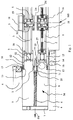
- the present invention relates to a closure system, in the illustrated example of a pocket type, with an opening 100 made in a wall 4 of a building, more particularly with reference to FIGS. 1, 2 and 5, advantageously at least one slider 3 comprising a window 50 made of a material capable of passing light radiation and constituting a heat shield and a frame 52 supporting the window 50, at least one concealment flap 1 of the opening 100, advantageously at least one housing open 54 made in the thickness of the wall 4, the open housing 54 opening on an edge 56 of the opening 100 and having dimensions defined so that the slider 3 and the flap 1 are adapted to be housed therein at least partially, and means 60 (FIG.
- the given direction Dd is the same for the sliding 3 and the shutter 1, and that in addition it is substantially horizontal.
- the open housing 54 is made in the wall 4 at the same level as the opening and opens on one of the two vertical sides of this opening.
- the shutter 1 and the slider 3 are constituted in two parts, but that they could equally well be made in more than two parts, or in one part.
- the shutters 1 are shown as intended to be arranged in the housing made in the wall, but that these shutters could just as easily be placed in the wall, preferably outside the wall, from both sides.
- the sliding comprising a window made of a material capable of allowing the light radiation to pass through and constituting a heat shield which may in this case be a pocket type or not.
- each flap portion 1 and each sliding portion 3 are adapted to be housed in two housings 54 made in the wall 4 on either side of the opening 100.
- the frame 52 defined above, and as illustrated in Figures 1 and 2, consists essentially of an internal vertical upright 12, two horizontal high and low crosspieces 17 and an outer vertical upright 18, 19.
- the slider consists of two parts as shown in Figure 1, the two vertical vertical uprights 18, 19 respectively belonging to the two sliding parts, are adapted to cooperate together, for example by interlocking, when the two sliding parts completely obscure the opening 100 as shown in Figure 1.
- the flap 1 preferably comprises a frame having substantially the same shape as that of the sliding and delimiting a frame, and a plurality of orientable blades 2 mounted in the frame in cooperation with the frame as described below. These steerable blades are arranged to be able to take two positions, a first "folded” position and a second "deployed” position.
- the system shown is advantageously designed so that, in terms of space and aesthetics, when the two elements constituted by the shutter 1 and the slider 3 are in their open position, that is to say when they are fully contained in the open housing 54, the opening 100 is completely clear. In said closed position, the internal vertical uprights 12 and the high rails 17 are completely hidden and contained in the housing 54.
- the open housing 54 defined above can thus be made entirely in the masonry of the wall 4 or between the masonry and a wall facing, for example a plating of thermal insulating material or the like.
- the thermal performance of the building in which the opening 100 is made is retained, in particular at the sliding 3.
- This purpose is obtained for example by means of insulating bars 5 arranged inside aluminum profiles constituting for example the vertical upright 18, 19.
- the system according to the invention comprises, in its discharge zone in the open housing 54, a wall vertical 6, for example in a thermal insulating material, fixed on the faces of the open housing 54 preferably through profiles 7.
- This wall 6 has the effect of creating two independent boxes 8, 9 without communication one with the other, one for the shutter 1 the other for the shutter 3.
- the insulating wall 6 is extended towards the outlet of the housing 54 by an extension profile 10 making it possible to support friction seals 11 between this extension profile 10 and the two uprights.
- internal verticals 12 respectively of the shutter 1 and the slider 3 when they are in their closed position, FIG.
- the profiles constituting the vertical uprights 12 of the frame of the slider 3 and the shutter 1 are provided with connecting pieces 13 which are well known technicians in the terminology of baffles.
- the baffle 13 on the side 1 flap for example clings to a section 14 secured to the wall 4 and high and low rails for the displacement respectively of the shutter 1 and the sliding 3.
- the baffle 13 sliding side 3 is hooked on a reinforced section 15 secured to the high and low rails.
- the baffles 13 may each further comprise a seal 16.
- the flap 1 is advantageously of the type with blades 2 which can be oriented to let the light while ensuring the function of "sunbreak".
- the adjustable blades can provide a very wide and varied range of lighting atmospheres, that do not allow the shutters.
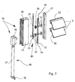
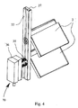
- FIG. 1 and 2 An advantageous embodiment of such a flap type blade 2 is more particularly illustrated in Figures 1 and 2 as a whole, and in more detail in Figures 3 and 4.
- each blade 2 is in the general form of a rectangular parallelepiped and essentially comprises a tube 21 of advantageously rectangular section located towards the upper part of the blade, a groove 22 also located in the upper part of the blade with advantageously a seal 23 on which is able to rest the lower face 24 of the upper blade, that is to say located just above in the normal position of the system according to the invention, and a cage 25 in which is housed a mass piece of the solid profiled type or the like to act as a counterweight in order to balance the blade when it is in its deployed position and can therefore be in overflow, figure 4.
- Each blade 2 may also consist of plates superimposed on one another while delimiting between them a free space, in order to introduce into this space, if necessary, a layer 26 of a non-heat conducting material. .
- the system according to the invention comprises means 70 for controlling the orientation of the blades 2, which essentially comprise motorization means 90 and a control mechanism 80 coupling the motorization means 90 and the blades 2.
- the control means 70 of the orientation of the blades 2 must have the smallest possible footprint while allowing to give the blades a large overhang in their deployed position to fulfill their function of solar breeze, that is to say to say to make them undergo a rotation which can be of the order of ninety degrees.
- the height of the blades 2 is such that once they are deployed beyond a certain angle opening, they prevent the insertion of the flap 1 in the opening 100.
- the flap can no longer enter the housing 100 in the case of an application of the shutter in a pocket closure system as shown in the figures.
- FIG. 2 or 4 shows, for example, blades 2 which extend out of the cross-section of the flap, as defined by the chassis thereof, as soon as they begin to open.
- the profile of the vertical vertical upright 12 of the flap frame has on its rear face a linear cavity 20 whose function will be defined below.
- each blade 2 has a finishing flange 28 on each of its ends ( Figure 3).
- the control mechanism 80 comprises trainers 29 which fit into the section 21 of each blade 2, the locking of the connection with this blade is by causing the driver 29 to expand by means of, for example, a wedge 30.
- the rotation guidance of the drivers 29 is ensured by a bearing 31 mounted on a profile 27.
- Each driver 29 is equipped with two cylindrical pins 32 on which connect two pre-drilled 33 drive rods.
- the basic trainer is substituted for a main trainer 34 which has the same characteristics but to which a coupling zone 35 is added.
- This coupling zone 35 passes through the internal vertical profile 12 and connects to an angle gear 36.
- the angle gear 36 is itself coupled to a tubular motor 37 fixed on a bracket 38, which constitutes the drive means 90 defined above.
- the angle return assembly 36, tubular motor 37 and bracket 38 is fixed in the linear cavity 20 defined previously.
- the system further comprises an electronic sensor adapted to recognize the position of the blades 2 and to allow the passage of the shutter 1 from its closed position to its open position only when the blades are in the folded position.
- an electronic sensor adapted to recognize the position of the blades 2 and to allow the passage of the shutter 1 from its closed position to its open position only when the blades are in the folded position.
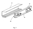
- the means 60 allowing the translational movement of the slider 3 and the shutter 1, they are provided by a conventional motor assembly which is mounted in cooperation with sliding rails integral with the bottom of the opening 100 and the housing 54 and by rolling carriages integral with the bottom of the sliding 3 and the shutter 1.
- Part of these translational displacement means 60 comprises, in a known manner, means for counter-pulley, toothed belt, belt gear, etc., schematically illustrated in FIG.
- the latter further comprises a beam 39 on which is associated all of the translational movement means 60 .
- a toothed belt 40 is disposed on each side of the beam 39.
- the beam 39 placed in a box 41 arranged for this purpose, the beam 39 creates two separate boxes, one in the right of the shutter 1, the other on the sliding right 3.
- the shutter as described above may find application in the aperture, that the associated sliding is of type or not.
Landscapes
- Engineering & Computer Science (AREA)
- Civil Engineering (AREA)
- Structural Engineering (AREA)
- Operating, Guiding And Securing Of Roll- Type Closing Members (AREA)
Applications Claiming Priority (1)
| Application Number | Priority Date | Filing Date | Title |
|---|---|---|---|
| FR0509741A FR2891299B1 (fr) | 2005-09-23 | 2005-09-23 | Systeme de fermeture a galandage d'une ouverture pratiquee dans un mur. |
Publications (1)
| Publication Number | Publication Date |
|---|---|
| EP1767738A2 true EP1767738A2 (de) | 2007-03-28 |
Family
ID=36577362
Family Applications (1)
| Application Number | Title | Priority Date | Filing Date |
|---|---|---|---|
| EP20060352016 Withdrawn EP1767738A2 (de) | 2005-09-23 | 2006-09-22 | Schliesssystem einer Öffnung in einer Wand |
Country Status (2)
| Country | Link |
|---|---|
| EP (1) | EP1767738A2 (de) |
| FR (1) | FR2891299B1 (de) |
Cited By (4)
| Publication number | Priority date | Publication date | Assignee | Title |
|---|---|---|---|---|
| EP3168409A4 (de) * | 2014-07-11 | 2018-03-21 | C3 Systems, S.L. | Dichtung für ober- und/oder untere profilen von verschlüssen |
| EP3591155A1 (de) * | 2018-07-05 | 2020-01-08 | SSC Öhns Snickeri AB | Schiebetürsystem mit schiebetür und wandmodul |
| WO2023007294A1 (en) * | 2021-07-30 | 2023-02-02 | Seu Plastics One Man L.L.C. | Fixed casement for partition with thermal break |
| CN117403994A (zh) * | 2023-12-13 | 2024-01-16 | 佛山市威尔普斯门窗有限公司 | 一种感应式智能滑轨门窗系统 |
Family Cites Families (2)
| Publication number | Priority date | Publication date | Assignee | Title |
|---|---|---|---|---|
| DE434474C (de) * | 1922-03-31 | 1926-09-23 | Eugenio Cattaneo | Wagerecht verschiebbares Fenster |
| US2355803A (en) * | 1943-12-08 | 1944-08-15 | Fred B Hopewell | Window unit |
-
2005
- 2005-09-23 FR FR0509741A patent/FR2891299B1/fr not_active Expired - Fee Related
-
2006
- 2006-09-22 EP EP20060352016 patent/EP1767738A2/de not_active Withdrawn
Cited By (5)
| Publication number | Priority date | Publication date | Assignee | Title |
|---|---|---|---|---|
| EP3168409A4 (de) * | 2014-07-11 | 2018-03-21 | C3 Systems, S.L. | Dichtung für ober- und/oder untere profilen von verschlüssen |
| EP3591155A1 (de) * | 2018-07-05 | 2020-01-08 | SSC Öhns Snickeri AB | Schiebetürsystem mit schiebetür und wandmodul |
| WO2023007294A1 (en) * | 2021-07-30 | 2023-02-02 | Seu Plastics One Man L.L.C. | Fixed casement for partition with thermal break |
| CN117403994A (zh) * | 2023-12-13 | 2024-01-16 | 佛山市威尔普斯门窗有限公司 | 一种感应式智能滑轨门窗系统 |
| CN117403994B (zh) * | 2023-12-13 | 2024-02-23 | 佛山市威尔普斯门窗有限公司 | 一种感应式智能滑轨门窗系统 |
Also Published As
| Publication number | Publication date |
|---|---|
| FR2891299B1 (fr) | 2009-02-13 |
| FR2891299A1 (fr) | 2007-03-30 |
Similar Documents
| Publication | Publication Date | Title |
|---|---|---|
| EP1953326A1 (de) | Flügelrahmen einer Schiebetür oder eines Schiebefensters, der einen verdeckten Pfosten umfasst | |
| CH693858A5 (fr) | Fenêtre ou porte-fenêtre à frappe à ouvrant(s) caché(s) | |
| EP2535497B1 (de) | Einrichtung zur wärmeisolierung und für den sonnenschutz | |
| EP1767738A2 (de) | Schliesssystem einer Öffnung in einer Wand | |
| FR2845415A1 (fr) | Fenetre, porte, porte-fenetre ou analogue pour habitation, lieu de travail ou abri, fixe ou mobile comportant un caisson ou coffre de volet roulant dans l'ouvrant | |
| EP0383709B1 (de) | Mobiles Verschlussmittel für Wandöffnung | |
| EP4460611B1 (de) | Isolierender rahmen für die aufnahme eines fensters | |
| FR3055649A1 (fr) | Element de separation d'un local a moyen de jonction de parement a ame elastique | |
| FR2690474A1 (fr) | Revêtement isolant, notamment pour toiture de véranda. | |
| FR2516159A1 (fr) | Systeme d'isolation des ouvertures de facade d'un immeuble | |
| FR2850423A1 (fr) | Dispositif de joint pour systeme de fermeture de baie a au moins un vantail coulissant | |
| FR2557915A1 (fr) | Volet perfectionne destine a faire office de persienne a lames orientables | |
| EP1896679B1 (de) | Neue art von rollladen | |
| EP4499944B1 (de) | Pfosten zur befestigung eines paneels sowie französischer balkon, sichtschutz oder sonnenschutz mit einem solchen pfosten | |
| FR2826387A1 (fr) | Cloison a ossature de profiles en aluminium garnis d'un tasseau de bois, profiles garnis d'un tasseau et installations architecturales pourvues de tels profiles et cloisons a effet retardateur de feu | |
| FR3031544B1 (fr) | Menuiserie vitree pour baie de batiment | |
| FR3114603A1 (fr) | Menuiserie à double jalousie | |
| FR2574846A1 (fr) | Volet interieur pour fenetre dont le positionnement est reglable et procede d'obturation d'une fenetre | |
| FR2991706A1 (fr) | Cadre de menuiserie equipe d'un dispositif a vitrage respirant | |
| FR3073243A1 (fr) | Systeme de menuiserie comprenant un ouvrant a deplacement vertical | |
| FR2588036A1 (fr) | Volet roulant de protection pour ouverture dans les toitures | |
| EP4036344A1 (de) | Dachfenster | |
| FR2784710A1 (fr) | Fenetre ou porte-fenetre a frappe a ouvrant(s) cache(s) | |
| EP4530418A1 (de) | Überdeckende verschlussvorrichtung und sonnenblende für eine gebäudeöffnung | |
| FR2958317A1 (fr) | Volet roulant |
Legal Events
| Date | Code | Title | Description |
|---|---|---|---|
| PUAI | Public reference made under article 153(3) epc to a published international application that has entered the european phase |
Free format text: ORIGINAL CODE: 0009012 |
|
| AK | Designated contracting states |
Kind code of ref document: A2 Designated state(s): AT BE BG CH CY CZ DE DK EE ES FI FR GB GR HU IE IS IT LI LT LU LV MC NL PL PT RO SE SI SK TR |
|
| AX | Request for extension of the european patent |
Extension state: AL BA HR MK YU |
|
| RIN1 | Information on inventor provided before grant (corrected) |
Inventor name: MAZARD LAURENT Inventor name: LEROY, JEROME Inventor name: MONFORT BERNARD Inventor name: CLAUZET ROBERT |
|
| RIN1 | Information on inventor provided before grant (corrected) |
Inventor name: MAZARD LAURENT Inventor name: LEROY, JEROME Inventor name: MONFORT BERNARD Inventor name: CLAUZET ROBERT |
|
| STAA | Information on the status of an ep patent application or granted ep patent |
Free format text: STATUS: THE APPLICATION HAS BEEN WITHDRAWN |
|
| 18W | Application withdrawn |
Effective date: 20110603 |