EP1767757A2 - Elément mélangeur pour un système d'échappement - Google Patents
Elément mélangeur pour un système d'échappement Download PDFInfo
- Publication number
- EP1767757A2 EP1767757A2 EP06120632A EP06120632A EP1767757A2 EP 1767757 A2 EP1767757 A2 EP 1767757A2 EP 06120632 A EP06120632 A EP 06120632A EP 06120632 A EP06120632 A EP 06120632A EP 1767757 A2 EP1767757 A2 EP 1767757A2
- Authority
- EP
- European Patent Office
- Prior art keywords
- mixing member
- channel
- inlet
- exhaust gas
- channels
- Prior art date
- Legal status (The legal status is an assumption and is not a legal conclusion. Google has not performed a legal analysis and makes no representation as to the accuracy of the status listed.)
- Granted
Links
Images

Classifications
-
- F—MECHANICAL ENGINEERING; LIGHTING; HEATING; WEAPONS; BLASTING
- F02—COMBUSTION ENGINES; HOT-GAS OR COMBUSTION-PRODUCT ENGINE PLANTS
- F02D—CONTROLLING COMBUSTION ENGINES
- F02D41/00—Electrical control of supply of combustible mixture or its constituents
- F02D41/02—Circuit arrangements for generating control signals
- F02D41/14—Introducing closed-loop corrections
- F02D41/1438—Introducing closed-loop corrections using means for determining characteristics of the combustion gases; Sensors therefor
- F02D41/1439—Introducing closed-loop corrections using means for determining characteristics of the combustion gases; Sensors therefor characterised by the position of the sensor
-
- B—PERFORMING OPERATIONS; TRANSPORTING
- B01—PHYSICAL OR CHEMICAL PROCESSES OR APPARATUS IN GENERAL
- B01F—MIXING, e.g. DISSOLVING, EMULSIFYING OR DISPERSING
- B01F23/00—Mixing according to the phases to be mixed, e.g. dispersing or emulsifying
- B01F23/10—Mixing gases with gases
-
- B—PERFORMING OPERATIONS; TRANSPORTING
- B01—PHYSICAL OR CHEMICAL PROCESSES OR APPARATUS IN GENERAL
- B01F—MIXING, e.g. DISSOLVING, EMULSIFYING OR DISPERSING
- B01F25/00—Flow mixers; Mixers for falling materials, e.g. solid particles
- B01F25/40—Static mixers
- B01F25/42—Static mixers in which the mixing is affected by moving the components jointly in changing directions, e.g. in tubes provided with baffles or obstructions
- B01F25/43—Mixing tubes, e.g. wherein the material is moved in a radial or partly reversed direction
- B01F25/432—Mixing tubes, e.g. wherein the material is moved in a radial or partly reversed direction with means for dividing the material flow into separate sub-flows and for repositioning and recombining these sub-flows; Cross-mixing, e.g. conducting the outer layer of the material nearer to the axis of the tube or vice-versa
- B01F25/4321—Mixing tubes, e.g. wherein the material is moved in a radial or partly reversed direction with means for dividing the material flow into separate sub-flows and for repositioning and recombining these sub-flows; Cross-mixing, e.g. conducting the outer layer of the material nearer to the axis of the tube or vice-versa the subflows consisting of at least two flat layers which are recombined, e.g. using means having restriction or expansion zones
-
- F—MECHANICAL ENGINEERING; LIGHTING; HEATING; WEAPONS; BLASTING
- F01—MACHINES OR ENGINES IN GENERAL; ENGINE PLANTS IN GENERAL; STEAM ENGINES
- F01N—GAS-FLOW SILENCERS OR EXHAUST APPARATUS FOR MACHINES OR ENGINES IN GENERAL; GAS-FLOW SILENCERS OR EXHAUST APPARATUS FOR INTERNAL-COMBUSTION ENGINES
- F01N13/00—Exhaust or silencing apparatus characterised by constructional features
- F01N13/08—Other arrangements or adaptations of exhaust conduits
-
- F—MECHANICAL ENGINEERING; LIGHTING; HEATING; WEAPONS; BLASTING
- F01—MACHINES OR ENGINES IN GENERAL; ENGINE PLANTS IN GENERAL; STEAM ENGINES
- F01N—GAS-FLOW SILENCERS OR EXHAUST APPARATUS FOR MACHINES OR ENGINES IN GENERAL; GAS-FLOW SILENCERS OR EXHAUST APPARATUS FOR INTERNAL-COMBUSTION ENGINES
- F01N13/00—Exhaust or silencing apparatus characterised by constructional features
- F01N13/18—Construction facilitating manufacture, assembly, or disassembly
- F01N13/1872—Construction facilitating manufacture, assembly, or disassembly the assembly using stamp-formed parts or otherwise deformed sheet-metal
-
- F—MECHANICAL ENGINEERING; LIGHTING; HEATING; WEAPONS; BLASTING
- F01—MACHINES OR ENGINES IN GENERAL; ENGINE PLANTS IN GENERAL; STEAM ENGINES
- F01N—GAS-FLOW SILENCERS OR EXHAUST APPARATUS FOR MACHINES OR ENGINES IN GENERAL; GAS-FLOW SILENCERS OR EXHAUST APPARATUS FOR INTERNAL-COMBUSTION ENGINES
- F01N13/00—Exhaust or silencing apparatus characterised by constructional features
- F01N13/18—Construction facilitating manufacture, assembly, or disassembly
- F01N13/1888—Construction facilitating manufacture, assembly, or disassembly the housing of the assembly consisting of two or more parts, e.g. two half-shells
- F01N13/1894—Construction facilitating manufacture, assembly, or disassembly the housing of the assembly consisting of two or more parts, e.g. two half-shells the parts being assembled in longitudinal direction
-
- F—MECHANICAL ENGINEERING; LIGHTING; HEATING; WEAPONS; BLASTING
- F01—MACHINES OR ENGINES IN GENERAL; ENGINE PLANTS IN GENERAL; STEAM ENGINES
- F01N—GAS-FLOW SILENCERS OR EXHAUST APPARATUS FOR MACHINES OR ENGINES IN GENERAL; GAS-FLOW SILENCERS OR EXHAUST APPARATUS FOR INTERNAL-COMBUSTION ENGINES
- F01N3/00—Exhaust or silencing apparatus having means for purifying, rendering innocuous, or otherwise treating exhaust
- F01N3/08—Exhaust or silencing apparatus having means for purifying, rendering innocuous, or otherwise treating exhaust for rendering innocuous
- F01N3/10—Exhaust or silencing apparatus having means for purifying, rendering innocuous, or otherwise treating exhaust for rendering innocuous by thermal or catalytic conversion of noxious components of exhaust
- F01N3/18—Exhaust or silencing apparatus having means for purifying, rendering innocuous, or otherwise treating exhaust for rendering innocuous by thermal or catalytic conversion of noxious components of exhaust characterised by methods of operation; Control
- F01N3/20—Exhaust or silencing apparatus having means for purifying, rendering innocuous, or otherwise treating exhaust for rendering innocuous by thermal or catalytic conversion of noxious components of exhaust characterised by methods of operation; Control specially adapted for catalytic conversion
- F01N3/206—Adding periodically or continuously substances to exhaust gases for promoting purification, e.g. catalytic material in liquid form, NOx reducing agents
- F01N3/2066—Selective catalytic reduction [SCR]
-
- F—MECHANICAL ENGINEERING; LIGHTING; HEATING; WEAPONS; BLASTING
- F01—MACHINES OR ENGINES IN GENERAL; ENGINE PLANTS IN GENERAL; STEAM ENGINES
- F01N—GAS-FLOW SILENCERS OR EXHAUST APPARATUS FOR MACHINES OR ENGINES IN GENERAL; GAS-FLOW SILENCERS OR EXHAUST APPARATUS FOR INTERNAL-COMBUSTION ENGINES
- F01N3/00—Exhaust or silencing apparatus having means for purifying, rendering innocuous, or otherwise treating exhaust
- F01N3/08—Exhaust or silencing apparatus having means for purifying, rendering innocuous, or otherwise treating exhaust for rendering innocuous
- F01N3/10—Exhaust or silencing apparatus having means for purifying, rendering innocuous, or otherwise treating exhaust for rendering innocuous by thermal or catalytic conversion of noxious components of exhaust
- F01N3/24—Exhaust or silencing apparatus having means for purifying, rendering innocuous, or otherwise treating exhaust for rendering innocuous by thermal or catalytic conversion of noxious components of exhaust characterised by constructional aspects of converting apparatus
- F01N3/28—Construction of catalytic reactors
- F01N3/2892—Exhaust flow directors or the like, e.g. upstream of catalytic device
-
- F—MECHANICAL ENGINEERING; LIGHTING; HEATING; WEAPONS; BLASTING
- F01—MACHINES OR ENGINES IN GENERAL; ENGINE PLANTS IN GENERAL; STEAM ENGINES
- F01N—GAS-FLOW SILENCERS OR EXHAUST APPARATUS FOR MACHINES OR ENGINES IN GENERAL; GAS-FLOW SILENCERS OR EXHAUST APPARATUS FOR INTERNAL-COMBUSTION ENGINES
- F01N2240/00—Combination or association of two or more different exhaust treating devices, or of at least one such device with an auxiliary device, not covered by indexing codes F01N2230/00 or F01N2250/00, one of the devices being
- F01N2240/20—Combination or association of two or more different exhaust treating devices, or of at least one such device with an auxiliary device, not covered by indexing codes F01N2230/00 or F01N2250/00, one of the devices being a flow director or deflector
-
- F—MECHANICAL ENGINEERING; LIGHTING; HEATING; WEAPONS; BLASTING
- F01—MACHINES OR ENGINES IN GENERAL; ENGINE PLANTS IN GENERAL; STEAM ENGINES
- F01N—GAS-FLOW SILENCERS OR EXHAUST APPARATUS FOR MACHINES OR ENGINES IN GENERAL; GAS-FLOW SILENCERS OR EXHAUST APPARATUS FOR INTERNAL-COMBUSTION ENGINES
- F01N2470/00—Structure or shape of exhaust gas passages, pipes or tubes
- F01N2470/14—Plurality of outlet tubes, e.g. in parallel or with different length
-
- F—MECHANICAL ENGINEERING; LIGHTING; HEATING; WEAPONS; BLASTING
- F01—MACHINES OR ENGINES IN GENERAL; ENGINE PLANTS IN GENERAL; STEAM ENGINES
- F01N—GAS-FLOW SILENCERS OR EXHAUST APPARATUS FOR MACHINES OR ENGINES IN GENERAL; GAS-FLOW SILENCERS OR EXHAUST APPARATUS FOR INTERNAL-COMBUSTION ENGINES
- F01N2470/00—Structure or shape of exhaust gas passages, pipes or tubes
- F01N2470/16—Plurality of inlet tubes, e.g. discharging into different chambers
-
- F—MECHANICAL ENGINEERING; LIGHTING; HEATING; WEAPONS; BLASTING
- F01—MACHINES OR ENGINES IN GENERAL; ENGINE PLANTS IN GENERAL; STEAM ENGINES
- F01N—GAS-FLOW SILENCERS OR EXHAUST APPARATUS FOR MACHINES OR ENGINES IN GENERAL; GAS-FLOW SILENCERS OR EXHAUST APPARATUS FOR INTERNAL-COMBUSTION ENGINES
- F01N2560/00—Exhaust systems with means for detecting or measuring exhaust gas components or characteristics
- F01N2560/02—Exhaust systems with means for detecting or measuring exhaust gas components or characteristics the means being an exhaust gas sensor
- F01N2560/021—Exhaust systems with means for detecting or measuring exhaust gas components or characteristics the means being an exhaust gas sensor for measuring or detecting ammonia NH3
-
- F—MECHANICAL ENGINEERING; LIGHTING; HEATING; WEAPONS; BLASTING
- F01—MACHINES OR ENGINES IN GENERAL; ENGINE PLANTS IN GENERAL; STEAM ENGINES
- F01N—GAS-FLOW SILENCERS OR EXHAUST APPARATUS FOR MACHINES OR ENGINES IN GENERAL; GAS-FLOW SILENCERS OR EXHAUST APPARATUS FOR INTERNAL-COMBUSTION ENGINES
- F01N2610/00—Adding substances to exhaust gases
- F01N2610/02—Adding substances to exhaust gases the substance being ammonia or urea
-
- F—MECHANICAL ENGINEERING; LIGHTING; HEATING; WEAPONS; BLASTING
- F02—COMBUSTION ENGINES; HOT-GAS OR COMBUSTION-PRODUCT ENGINE PLANTS
- F02D—CONTROLLING COMBUSTION ENGINES
- F02D41/00—Electrical control of supply of combustible mixture or its constituents
- F02D41/02—Circuit arrangements for generating control signals
- F02D41/14—Introducing closed-loop corrections
- F02D41/1438—Introducing closed-loop corrections using means for determining characteristics of the combustion gases; Sensors therefor
- F02D41/1444—Introducing closed-loop corrections using means for determining characteristics of the combustion gases; Sensors therefor characterised by the characteristics of the combustion gases
- F02D2041/1468—Introducing closed-loop corrections using means for determining characteristics of the combustion gases; Sensors therefor characterised by the characteristics of the combustion gases the characteristics being an ammonia content or concentration of the exhaust gases
-
- Y—GENERAL TAGGING OF NEW TECHNOLOGICAL DEVELOPMENTS; GENERAL TAGGING OF CROSS-SECTIONAL TECHNOLOGIES SPANNING OVER SEVERAL SECTIONS OF THE IPC; TECHNICAL SUBJECTS COVERED BY FORMER USPC CROSS-REFERENCE ART COLLECTIONS [XRACs] AND DIGESTS
- Y02—TECHNOLOGIES OR APPLICATIONS FOR MITIGATION OR ADAPTATION AGAINST CLIMATE CHANGE
- Y02A—TECHNOLOGIES FOR ADAPTATION TO CLIMATE CHANGE
- Y02A50/00—TECHNOLOGIES FOR ADAPTATION TO CLIMATE CHANGE in human health protection, e.g. against extreme weather
- Y02A50/20—Air quality improvement or preservation, e.g. vehicle emission control or emission reduction by using catalytic converters
-
- Y—GENERAL TAGGING OF NEW TECHNOLOGICAL DEVELOPMENTS; GENERAL TAGGING OF CROSS-SECTIONAL TECHNOLOGIES SPANNING OVER SEVERAL SECTIONS OF THE IPC; TECHNICAL SUBJECTS COVERED BY FORMER USPC CROSS-REFERENCE ART COLLECTIONS [XRACs] AND DIGESTS
- Y02—TECHNOLOGIES OR APPLICATIONS FOR MITIGATION OR ADAPTATION AGAINST CLIMATE CHANGE
- Y02T—CLIMATE CHANGE MITIGATION TECHNOLOGIES RELATED TO TRANSPORTATION
- Y02T10/00—Road transport of goods or passengers
- Y02T10/10—Internal combustion engine [ICE] based vehicles
- Y02T10/12—Improving ICE efficiencies
Definitions
- the present invention relates to a mixing element for an exhaust system of an internal combustion engine, in particular of a motor vehicle.
- the invention also relates to an exhaust system equipped with such a mixing element.
- Exhaust systems of internal combustion engines can be configured in two columns, that is to say have two separate exhaust lines which discharge the exhaust gases in parallel from the internal combustion engine.
- dual-flow exhaust systems are useful in V-engines to dissipate the exhaust gases of the two cylinder banks separately.
- exhaust gas purification devices such as catalysts and particulate filters.
- This functional test is of increased importance in catalyst arrangements, in which an oxidation catalyst is followed by a catalyst with selective catalytic reduction, abbreviated to SCR catalyst, wherein upstream of the SCR catalyst ammonia or urea, which is converted into ammonia due to the high exhaust gas temperatures, is introduced.
- SCR catalyst a catalyst with selective catalytic reduction
- a corresponding sensor can now be determined downstream of the catalyst arrangement, whether a residual amount of ammonia or urea is contained in the exhaust gas.
- the proper function of the catalyst arrangement can be assessed. Possibly. can also be intervened in the control or regulation of the catalyst arrangement accordingly.
- the invention is concerned with the problem of finding a way by which the function monitoring of provided in the exhaust gas lines catalyst arrangements can be made cheaper in a twin-flow exhaust system.
- the invention is based on the general idea to provide for the twin-flow exhaust system, a mixing member which is insertable via two inlet openings and two outlet openings in the two exhaust gas lines of a twin-flow exhaust system, wherein in the mixing member said four openings are interconnected so that each inlet opening with both Outlets is connected.
- a mixing member which is insertable via two inlet openings and two outlet openings in the two exhaust gas lines of a twin-flow exhaust system, wherein in the mixing member said four openings are interconnected so that each inlet opening with both Outlets is connected.
- exhaust gases entering through the one inlet opening in the mixing member exit through both outlet openings of the mixing member again.
- those exhaust gases which enter the mixing member via the other inlet opening also exit from the mixing member via both outlet openings.
- the mixing member includes a channel system, which connects each inlet opening via two separate channels with the two outlet openings.
- a predetermined mixing ratio between the two supplied exhaust gas streams can be achieved in both discharged exhaust gas flows.
- the flow resistance of the mixing element can be reduced with such a channel system.
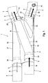
- a double-flow exhaust system 1 comprises two exhaust gas lines 2, 3, which lead exhaust gases away from an internal combustion engine, not shown, which is arranged in particular in a motor vehicle.
- the two exhaust gas lines 2, 3 are coupled to each other via a mixing member 4.
- the two exhaust gas lines 2, 3 are brought separately to the mixing member 4 and also led away separately from the mixing member 4.
- the mixing element 4 has two inlet openings, namely a first inlet opening 5 assigned to the first exhaust gas line 2 and a second inlet opening 6 assigned to the second exhaust line 3.
- This mixing element 4 is now configured so that each of its inlet openings 5, 6 with two outlet openings 7, 8 is communicatively connected.
- This special design has the consequence that a first exhaust gas flow 9, which is supplied upstream of the mixing member 4 via the first exhaust line 2 and which is symbolized in Fig. 1 by contour arrows, downstream of the mixing member 4 in both exhaust lines 2, 3 can be found.
- a second exhaust gas flow 10 which is supplied to the mixing element 4 via the second exhaust gas line 3 and which is symbolized in FIG. 1 by solid arrows.
- a respective catalyst arrangement is installed in each exhaust gas line 2, 3 upstream of the mixing element 4.
- a catalyst arrangement comprises an oxidation catalyst and an SCR catalyst arranged downstream thereof.
- the catalyst arrangement can be equipped with a urea supply device, which introduces urea into the respective exhaust gas line 2, 3 upstream of the SCR catalytic converter.
- the injected urea is converted into ammonia due to the prevailing high operating temperatures.
- nitrogen oxides can be reduced to nitrogen and water with the help of ammonia.
- a malfunction of the catalyst arrangement can be downstream of the catalyst assembly in the exhaust gas flow 9, 10 detect unwanted pollutants or pollutants in undesirably high concentrations.
- a malfunction of the previously exemplified catalyst arrangement in the exhaust gas lead to an undesirably high urea content or ammonia content.
- the proposed mixing element 4 now offers the possibility of analyzing the exhaust gases 9, 10 of both exhaust gas lines 2, 3 downstream of the mixing element 4 with the aid of only one single sensor 11. Because downstream of the mixing member 4 prevails in each exhaust line 2, 3, an exhaust gas mixture, which is composed of the exhaust gases 9, 10 of the two exhaust gas lines 2, 3 upstream of the mixing member 4. For example, should the SCR catalyst or the urea supply in one of the two exhaust lines 2, 3 have a malfunction that leads to an excessive urea content or ammonia content in the exhaust gas 9, 10 downstream of the respective catalyst arrangement, this can be done with a sufficient concentration of ammonia or urea using the probe 11 detected, regardless of whether the sensor 11 in the first exhaust line 2 or in the second exhaust line 3 is located. It is clear that in principle also several sensors 11 or probes 11 can be provided, which are specialized redundantly and / or with respect to different analyzes.
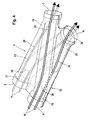
- the mixing member 4 includes a channel system 12.
- This channel system 12 comprises a total of four channels.
- a first channel 13 connects the first inlet opening 5 with the first outlet opening 7.
- the first channel 13 extends substantially rectilinearly and perpendicular to an opening plane of the first inlet opening 5.
- the first channel 13 extends substantially in the longitudinal direction of the mixing member 4th
- a second channel 14 connects the second inlet opening 6 with the second outlet opening 8. Also, the second channel 14 extends substantially straight and perpendicular to an opening plane of the second inlet opening 6. The second channel 14 thus extends with respect to the rectangular shape of the mixing member 4 also in its longitudinal direction.
- a third channel 15 connects the first inlet opening 5 with the second outlet opening 8.
- the third channel 15 thus extends substantially diagonally to the rectangular basic shape of the mixing element 4.
- a longitudinal direction of the third channel 15 is substantially perpendicular to an opening plane of the second outlet opening 8 ,
- a fourth channel 16 connects the second inlet opening 6 with the first outlet opening 7. With respect to the rectangular basic shape of the mixing element 4, the fourth also extends Channel 16 diagonal. In particular, a longitudinal direction of the fourth channel 16 is substantially perpendicular to an opening plane of the first outlet opening 7.
- the channel system 12 for each opening 5 to 8 comprises two channels 13 to 16 for separate connection to the two opposing openings 5 to 8.
- first inlet opening 5 is above the first channel 13 with the first outlet opening 7 and independently across the third Channel 15 is connected to the second outlet opening 8.
- the second inlet opening 6 is connected via the fourth channel 16 to the first outlet opening 7 and independently via the second channel 14 to the second outlet opening 8.
- first outlet opening 7 is connected via the first channel 13 to the first inlet opening 5 and independently via the fourth channel 16 to the second inlet opening 6.
- the second outlet opening 8 is connected to the second inlet opening 6 via the second channel 14 and independently to the first inlet opening 5 via the third channel 15.
- the mixing member 2 has an inlet space, namely a first inlet space 17 and a second inlet space 18, for each inlet opening 5, 6.
- an outlet space is also provided for each outlet opening 7, 8, namely a first outlet space 19 and a second outlet space 20.
- the first channel 13 and the third channel 15 branch off to the outlet openings 7, 8.
- branch off from the second inlet space 18 the second channel 14 and the fourth channel 16 to the outlet openings 7, 8 from.
- the first channel 13 and the fourth channel 16 open into the first outlet space 19.
- the second channel 14 and the third channel 15 open into the second outlet space 20.
- Figs. 1 to 4 can be clearly seen that at each opening 5 to 8, the two associated channels 13 to 16 are arranged in a Y-shape. Furthermore, two of the four channels, namely, the first channel 13 and the second channel 14 are substantially parallel to each other. In this case, these two channels 13, 14 extend apart from each other, such that the exhaust gas flows flowing through these channels 13, 14 do not mix with each other.
- the two other channels 15, 16 are arranged so that they are crossed to one another, that is, the two channels 15, 16 intersect in the plan views of FIGS. 2 and 3 X-shaped. Also, for these two channels 15, 16, the channel system 12 is designed so that exhaust gas flows that flow through these two channels 15, 16, do not mix with each other in the mixing member 4.
- the channel system 12 is designed so that all four channels 13 to 16 have approximately equal flow cross-sections. This is intended to ensure that the two, the mixing member 4 supplied exhaust gas flows 9, 10 on the inlet side of the mixing member 4 evenly, so split in half and the outlet side of the mixing member 4 recombine again to the same size exhaust gas flows.
- the mixing member 4 is preferably assembled from two half-shells, namely from an upper shell 21 visible in FIG. 2 and a lower shell 22 visible in FIG. Furthermore, an insert plate 23 is provided, which is arranged between the two half-shells 21, 22. The section in Fig. 3 is placed so that the insert plate 23 is visible. It can be seen that the insert plate 23 is dimensioned so that it extends on the longitudinal sides of the mixing member 4 to the outside and is integrated into a portion of the longitudinal edge of the mixing member 4. Along the edge, the half-shells 21, 22 are fastened to each other and in said edge portion also on the insert plate 23, for example by welding and / or soldering.
- each half-shell 21, 22 is suitably deep-drawn parts and are preferably designed as identical parts.
- each half-shell 21, 22 comprises two inlet opening sections 24, two outlet opening sections 25 and two channel sections 26, 27.
- the channel sections 26, 27 are open to the respective other half-shell 21, 22.
- the two channel sections 26, 27 connect the first outlet opening 7 with the two inlet openings 5, 6 in the upper shell 21 and the second outlet opening 8 with the two inlet openings 5, 6 in the lower shell 22.
- the insert plate 23 is now shaped so that it closes in the assembled state said channel sections 26, 27 respectively to the other half-shell 21, 22, but only in the portions of the channels 13 to 16 between the inlet chambers 17, 18 and the outlet chambers 19, 20th Furthermore, the insert plate 23 forms in the inlet spaces 17, 18 in each case a leading edge 28, into which the incoming exhaust gas flow 9, 10 divides into the two outlets 13 to 16 emerging from the respective inlet space 17, 18.
- the first exhaust gas flow 9 supplied via the first exhaust gas line 2 is subdivided into a first partial flow 29 and a second partial flow 30 in the first inlet space 17.
- the first partial flow 29 follows the first channel 13 and exits from the mixing member 4 via the first outlet space 19 through the first outlet opening 7.
- the second partial flow 30 follows the third channel 15 and exits from the mixing member 4 via the second outlet space 20 through the second outlet opening 8.
- the second exhaust gas flow 10 supplied via the second exhaust gas line 3 is split in the second inlet space 18 into a third partial flow 31 and a fourth partial flow 32.
- the third partial flow 31 passes through the second channel 14 into the second outlet space 20 and out of the mixing element 4 via the second outlet opening 8.
- the fourth partial flow 32 flows out of the mixing member 4 through the fourth passage 16 via the first outlet space 19 through the first outlet opening 7.
- the first outlet 19 mixed the first partial flow 29 with the fourth partial flow 32.
- the second partial flow 30 is mixed with the third partial flow 31 in the second outlet space 20.
Landscapes
- Engineering & Computer Science (AREA)
- Chemical & Material Sciences (AREA)
- Chemical Kinetics & Catalysis (AREA)
- Combustion & Propulsion (AREA)
- Mechanical Engineering (AREA)
- General Engineering & Computer Science (AREA)
- Health & Medical Sciences (AREA)
- Toxicology (AREA)
- Dispersion Chemistry (AREA)
- Exhaust Gas After Treatment (AREA)
- Exhaust Silencers (AREA)
Applications Claiming Priority (1)
| Application Number | Priority Date | Filing Date | Title |
|---|---|---|---|
| DE102005046316A DE102005046316A1 (de) | 2005-09-27 | 2005-09-27 | Mischglied für eine Abgasanlage |
Publications (3)
| Publication Number | Publication Date |
|---|---|
| EP1767757A2 true EP1767757A2 (fr) | 2007-03-28 |
| EP1767757A3 EP1767757A3 (fr) | 2009-03-11 |
| EP1767757B1 EP1767757B1 (fr) | 2015-11-11 |
Family
ID=37657634
Family Applications (1)
| Application Number | Title | Priority Date | Filing Date |
|---|---|---|---|
| EP06120632.2A Active EP1767757B1 (fr) | 2005-09-27 | 2006-09-14 | Elément mélangeur pour un système d'échappement |
Country Status (3)
| Country | Link |
|---|---|
| US (1) | US7596944B2 (fr) |
| EP (1) | EP1767757B1 (fr) |
| DE (1) | DE102005046316A1 (fr) |
Cited By (2)
| Publication number | Priority date | Publication date | Assignee | Title |
|---|---|---|---|---|
| WO2009000543A1 (fr) | 2007-06-27 | 2008-12-31 | Faurecia Abgastechnik Gmbh | Installation de gaz d'échappement pour moteur à combustion interne présentant deux lignes de gaz d'échappement et un système mélangeur |
| EP2199559A1 (fr) * | 2008-12-11 | 2010-06-23 | J. Eberspächer GmbH & Co. KG | Tuyau X et installation de gaz d'échappement correspondante |
Families Citing this family (13)
| Publication number | Priority date | Publication date | Assignee | Title |
|---|---|---|---|---|
| DE102006015964A1 (de) * | 2006-04-05 | 2007-10-18 | Arvinmeritor Emissions Technologies Gmbh | Baugruppe zur Vermischung eines Mediums mit dem Abgasstrom einer Kfz-Abgasanlage |
| DE102008022998B4 (de) | 2008-05-09 | 2011-10-20 | Audi Ag | Vorrichtung und Verfahren zur Reinigung von Abgasen für einen Abgasstrang einer Brennkraftmaschine |
| DE102008040293B4 (de) | 2008-07-09 | 2013-10-10 | Faurecia Abgastechnik Gmbh | Abgasanlage für einen Verbrennungsmotor |
| DE102008041289B4 (de) | 2008-08-15 | 2013-09-12 | Faurecia Abgastechnik Gmbh | Abgasanlage für einen Verbrennungsmotor |
| US8359847B2 (en) * | 2009-10-01 | 2013-01-29 | Albert Earl Hatchett | Device and method for converting a motorcycle exhaust system into a multiple exhaust system |
| US8999276B1 (en) | 2013-09-19 | 2015-04-07 | Caterpillar Inc. | System and method for mixing of fluids |
| JP6378611B2 (ja) * | 2014-10-29 | 2018-08-22 | 川崎重工業株式会社 | エンジンの排気装置 |
| USD887930S1 (en) | 2018-10-27 | 2020-06-23 | David Akiba Borla | Exhaust crossover assembly |
| US11746688B1 (en) | 2018-10-27 | 2023-09-05 | David Akiba Borla | Cross-pipe exhaust assembly |
| US11326501B2 (en) * | 2018-10-27 | 2022-05-10 | David Akiba Borla | Cross-pipe exhaust system |
| US11692470B2 (en) * | 2019-06-07 | 2023-07-04 | Tenneco Automotive Operating Company Inc. | Exhaust system and muffler |
| US11598236B2 (en) * | 2020-09-28 | 2023-03-07 | Ford Global Technologies, Llc | Exhaust system |
| USD1035523S1 (en) | 2023-01-06 | 2024-07-16 | David Akiba Borla | Exhaust muffler for an internal combustion engine |
Family Cites Families (16)
| Publication number | Priority date | Publication date | Assignee | Title |
|---|---|---|---|---|
| US3072214A (en) * | 1958-02-14 | 1963-01-08 | Oldberg Mfg Company | Gas blending and sound-attenuating system and apparatus |
| DE6912770U (de) * | 1969-03-28 | 1969-08-14 | Gillet Gmbh Paul | Rohrverbindung fuer doppelrohr-auspuffanlagen |
| US4342195A (en) * | 1980-08-15 | 1982-08-03 | Lo Ching P | Motorcycle exhaust system |
| US4953352A (en) * | 1985-08-26 | 1990-09-04 | Campbell Monty A | Exhaust system |
| DE3740238A1 (de) * | 1986-12-04 | 1988-06-23 | Audi Ag | Abgasanlage fuer eine brennkraftmaschine mit zwei zylinderbaenken |
| DE3721810A1 (de) * | 1987-07-02 | 1989-01-12 | Audi Ag | Abgasanlage fuer eine brennkraftmaschine mit zwei zylinderbaenken |
| SE467315B (sv) * | 1987-12-08 | 1992-06-29 | Stihl Maschf Andreas | Avgasljuddaempare foer tvaataktsmotorer, i synnerhet foer baerbara arbetsredskap |
| US4947645A (en) * | 1989-07-31 | 1990-08-14 | Pemberton Joseph H | Exhaust efficiency increasing apparatus |
| US5018349A (en) * | 1989-07-31 | 1991-05-28 | Pemberton Joseph H | Exhaust efficiency increasing apparatus |
| US5144799A (en) * | 1991-07-18 | 1992-09-08 | Barth Randolph S | Crossfire calibrated exhaust system |
| JP3740879B2 (ja) * | 1999-02-24 | 2006-02-01 | スズキ株式会社 | 自動二輪車の排気装置 |
| US6247305B1 (en) * | 1999-10-07 | 2001-06-19 | Darryl C. Bassani | Motorcycle exhaust system |
| JP2002089245A (ja) * | 2000-09-20 | 2002-03-27 | Calsonic Kansei Corp | 内燃機関の排気ガス浄化システム |
| DE10104021B4 (de) * | 2001-01-31 | 2013-04-25 | Daimler Ag | Abgasanlage |
| US6889499B2 (en) * | 2001-05-16 | 2005-05-10 | Darryl C. Bassani | Internal combustion engine exhaust system |
| US6546720B2 (en) * | 2001-09-04 | 2003-04-15 | Ford Global Technologies, Inc. | Method and apparatus for controlling the amount of reactant to be added to a substance using a sensor which is responsive to both the reactant and the substance |
-
2005
- 2005-09-27 DE DE102005046316A patent/DE102005046316A1/de not_active Withdrawn
-
2006
- 2006-09-14 EP EP06120632.2A patent/EP1767757B1/fr active Active
- 2006-09-22 US US11/526,143 patent/US7596944B2/en active Active
Cited By (4)
| Publication number | Priority date | Publication date | Assignee | Title |
|---|---|---|---|---|
| WO2009000543A1 (fr) | 2007-06-27 | 2008-12-31 | Faurecia Abgastechnik Gmbh | Installation de gaz d'échappement pour moteur à combustion interne présentant deux lignes de gaz d'échappement et un système mélangeur |
| DE102007030038A1 (de) | 2007-06-27 | 2009-01-02 | Faurecia Abgastechnik Gmbh | Abgasanlage für einen Verbrennungsmotor |
| EP2199559A1 (fr) * | 2008-12-11 | 2010-06-23 | J. Eberspächer GmbH & Co. KG | Tuyau X et installation de gaz d'échappement correspondante |
| US8209972B2 (en) | 2008-12-11 | 2012-07-03 | J. Eberspächer GmbH & Co. KG | X-tube and corresponding exhaust system |
Also Published As
| Publication number | Publication date |
|---|---|
| US7596944B2 (en) | 2009-10-06 |
| EP1767757A3 (fr) | 2009-03-11 |
| US20070068150A1 (en) | 2007-03-29 |
| EP1767757B1 (fr) | 2015-11-11 |
| DE102005046316A1 (de) | 2007-04-12 |
Similar Documents
| Publication | Publication Date | Title |
|---|---|---|
| EP1767757B1 (fr) | Elément mélangeur pour un système d'échappement | |
| EP1857651B1 (fr) | Équipement de post traitement des gaz d'échappement pour un moteur à combustion interne | |
| DE102011089969B4 (de) | Abgasbehandlungsvorrichtung | |
| DE102020127384B4 (de) | Probenentnahmevorrichtung für einen abgassensor | |
| DE102017217728A1 (de) | Verfahren zum Betreiben eines Abgasnachbehandlungssystems eines Dieselmotors und Abgasnachbehandlungssystem | |
| DE112014005929T5 (de) | Integrierte Sensorwasserabschirmung | |
| DE10393974T5 (de) | Abgaskrümmer | |
| EP0530655B1 (fr) | Méthode et dispositif de régulation d'un moteur à combustion interne avec contrÔle de son catalysateur | |
| EP4092256B1 (fr) | Installation de gaz d'échappement d'un moteur à combustion interne | |
| DE102007038516B4 (de) | Abgasanlage und Verfahren zum Betrieb der Abgasanlage | |
| DE69407557T2 (de) | Katalysatorüberwachung für Y-Abgasrohranordnung | |
| EP1604100B1 (fr) | Systeme de gaz d'echappement a lignes multiples comprenant au moins un detecteur, un corps a nid d'abeilles a logement pour au moins un detecteur, et procede de mise en action d'un tel systeme de gaz d'echappement a lignes multiples | |
| EP4095363B1 (fr) | Procédé de détermination d'un besoin de régénération pour un filtre particulaire des gaz d'échappement, ainsi qu'installation de gaz d'échappement | |
| DE102007007502A1 (de) | Verfahren und Vorrichtung zur Diagnose einer Abgasreinigungsanlage | |
| EP2171231A1 (fr) | Dispositif de purification des gaz d'échappement d'un moteur à combustion interne | |
| DE102021204807B4 (de) | Sensor-Anordnung, Abgasnachbehandlungseinrichtung, Brennkraftmaschine, Fahrzeug und Verfahren zum Betreiben einer Abgasnachbehandlungseinrichtung | |
| DE102019208869A1 (de) | Sensor-Anordnung zum Bestimmen wenigstens eines Abgasparameters in einer Abgasströmung, und Brennkraftmaschine mit einer solchen Sensor-Anordnung | |
| DE102018122844B4 (de) | Abgasnachbehandlungssystem sowie Verfahren zur Abgasnachbehandlung eines Verbrennungsmotors | |
| DE102006049531A1 (de) | Verbindungseinheit zur Montage in einem Abgasstrang einer Verbrennungskraftmaschine | |
| DE102008022998B4 (de) | Vorrichtung und Verfahren zur Reinigung von Abgasen für einen Abgasstrang einer Brennkraftmaschine | |
| DE3821345A1 (de) | Vorrichtung zum verringern von abgas-schadstoffkomponenten einer brennkraftmaschine | |
| DE102021106097B4 (de) | Abgasnachbehandlungssystem und Verfahren zur On-Board-Diagnose eines solchen Abgasnachbehandlungssystems | |
| DE102024107801B3 (de) | Verfahren zum Betreiben einer Antriebseinrichtung für ein Kraftfahrzeug, entsprechende Antriebseinrichtung sowie Computerprogrammprodukt | |
| DE10032571A1 (de) | Verfahren zur Zustandserfassung eines Katalysatorsystems | |
| DE102024106129A1 (de) | Dosiereinrichtung, Abgasanlage und Kraftfahrzeug |
Legal Events
| Date | Code | Title | Description |
|---|---|---|---|
| PUAI | Public reference made under article 153(3) epc to a published international application that has entered the european phase |
Free format text: ORIGINAL CODE: 0009012 |
|
| AK | Designated contracting states |
Kind code of ref document: A2 Designated state(s): AT BE BG CH CY CZ DE DK EE ES FI FR GB GR HU IE IS IT LI LT LU LV MC NL PL PT RO SE SI SK TR |
|
| AX | Request for extension of the european patent |
Extension state: AL BA HR MK YU |
|
| PUAL | Search report despatched |
Free format text: ORIGINAL CODE: 0009013 |
|
| AK | Designated contracting states |
Kind code of ref document: A3 Designated state(s): AT BE BG CH CY CZ DE DK EE ES FI FR GB GR HU IE IS IT LI LT LU LV MC NL PL PT RO SE SI SK TR |
|
| AX | Request for extension of the european patent |
Extension state: AL BA HR MK RS |
|
| 17P | Request for examination filed |
Effective date: 20090911 |
|
| AKX | Designation fees paid |
Designated state(s): DE FR GB IT SE |
|
| 17Q | First examination report despatched |
Effective date: 20100429 |
|
| RAP1 | Party data changed (applicant data changed or rights of an application transferred) |
Owner name: EBERSPAECHER EXHAUST TECHNOLOGY GMBH & CO. KG |
|
| REG | Reference to a national code |
Ref country code: DE Ref legal event code: R079 Ref document number: 502006014633 Country of ref document: DE Free format text: PREVIOUS MAIN CLASS: F01N0007180000 Ipc: F02D0041140000 |
|
| RIC1 | Information provided on ipc code assigned before grant |
Ipc: F01N 3/20 20060101ALI20150323BHEP Ipc: B01F 3/02 20060101ALI20150323BHEP Ipc: F01N 13/08 20100101ALI20150323BHEP Ipc: B01F 5/06 20060101ALI20150323BHEP Ipc: F02D 41/14 20060101AFI20150323BHEP Ipc: F01N 13/18 20100101ALI20150323BHEP Ipc: F01N 3/28 20060101ALI20150323BHEP |
|
| GRAP | Despatch of communication of intention to grant a patent |
Free format text: ORIGINAL CODE: EPIDOSNIGR1 |
|
| INTG | Intention to grant announced |
Effective date: 20150730 |
|
| GRAS | Grant fee paid |
Free format text: ORIGINAL CODE: EPIDOSNIGR3 |
|
| GRAA | (expected) grant |
Free format text: ORIGINAL CODE: 0009210 |
|
| AK | Designated contracting states |
Kind code of ref document: B1 Designated state(s): DE FR GB IT SE |
|
| REG | Reference to a national code |
Ref country code: GB Ref legal event code: FG4D Free format text: NOT ENGLISH |
|
| REG | Reference to a national code |
Ref country code: DE Ref legal event code: R096 Ref document number: 502006014633 Country of ref document: DE |
|
| REG | Reference to a national code |
Ref country code: SE Ref legal event code: TRGR |
|
| REG | Reference to a national code |
Ref country code: DE Ref legal event code: R097 Ref document number: 502006014633 Country of ref document: DE |
|
| PLBE | No opposition filed within time limit |
Free format text: ORIGINAL CODE: 0009261 |
|
| STAA | Information on the status of an ep patent application or granted ep patent |
Free format text: STATUS: NO OPPOSITION FILED WITHIN TIME LIMIT |
|
| REG | Reference to a national code |
Ref country code: FR Ref legal event code: PLFP Year of fee payment: 11 |
|
| 26N | No opposition filed |
Effective date: 20160812 |
|
| REG | Reference to a national code |
Ref country code: FR Ref legal event code: PLFP Year of fee payment: 12 |
|
| PGFP | Annual fee paid to national office [announced via postgrant information from national office to epo] |
Ref country code: IE Payment date: 20170609 Year of fee payment: 9 |
|
| REG | Reference to a national code |
Ref country code: FR Ref legal event code: PLFP Year of fee payment: 13 |
|
| PG25 | Lapsed in a contracting state [announced via postgrant information from national office to epo] |
Ref country code: IT Free format text: LAPSE BECAUSE OF NON-PAYMENT OF DUE FEES Effective date: 20180914 |
|
| REG | Reference to a national code |
Ref country code: DE Ref legal event code: R081 Ref document number: 502006014633 Country of ref document: DE Owner name: PUREM GMBH, DE Free format text: FORMER OWNER: EBERSPAECHER EXHAUST TECHNOLOGY GMBH & CO. KG, 66539 NEUNKIRCHEN, DE |
|
| PGFP | Annual fee paid to national office [announced via postgrant information from national office to epo] |
Ref country code: SE Payment date: 20230921 Year of fee payment: 18 |
|
| PGFP | Annual fee paid to national office [announced via postgrant information from national office to epo] |
Ref country code: DE Payment date: 20240919 Year of fee payment: 19 |
|
| PGFP | Annual fee paid to national office [announced via postgrant information from national office to epo] |
Ref country code: GB Payment date: 20240923 Year of fee payment: 19 |
|
| PGFP | Annual fee paid to national office [announced via postgrant information from national office to epo] |
Ref country code: FR Payment date: 20240924 Year of fee payment: 19 |
|
| REG | Reference to a national code |
Ref country code: SE Ref legal event code: EUG |
|
| PG25 | Lapsed in a contracting state [announced via postgrant information from national office to epo] |
Ref country code: SE Free format text: LAPSE BECAUSE OF NON-PAYMENT OF DUE FEES Effective date: 20240915 |