EP1767793A2 - Dispositif de fixation pour la fixation des panneaux solaires à un rail d'assemblage - Google Patents
Dispositif de fixation pour la fixation des panneaux solaires à un rail d'assemblage Download PDFInfo
- Publication number
- EP1767793A2 EP1767793A2 EP06120779A EP06120779A EP1767793A2 EP 1767793 A2 EP1767793 A2 EP 1767793A2 EP 06120779 A EP06120779 A EP 06120779A EP 06120779 A EP06120779 A EP 06120779A EP 1767793 A2 EP1767793 A2 EP 1767793A2
- Authority
- EP
- European Patent Office
- Prior art keywords
- fastening device
- fastening
- portions
- screw
- solar panels
- Prior art date
- Legal status (The legal status is an assumption and is not a legal conclusion. Google has not performed a legal analysis and makes no representation as to the accuracy of the status listed.)
- Withdrawn
Links
Images


Classifications
-
- F—MECHANICAL ENGINEERING; LIGHTING; HEATING; WEAPONS; BLASTING
- F16—ENGINEERING ELEMENTS AND UNITS; GENERAL MEASURES FOR PRODUCING AND MAINTAINING EFFECTIVE FUNCTIONING OF MACHINES OR INSTALLATIONS; THERMAL INSULATION IN GENERAL
- F16B—DEVICES FOR FASTENING OR SECURING CONSTRUCTIONAL ELEMENTS OR MACHINE PARTS TOGETHER, e.g. NAILS, BOLTS, CIRCLIPS, CLAMPS, CLIPS OR WEDGES; JOINTS OR JOINTING
- F16B5/00—Joining sheets or plates, e.g. panels, to one another or to strips or bars parallel to them
- F16B5/06—Joining sheets or plates, e.g. panels, to one another or to strips or bars parallel to them by means of clamps or clips
- F16B5/0607—Joining sheets or plates, e.g. panels, to one another or to strips or bars parallel to them by means of clamps or clips joining sheets or plates to each other
- F16B5/0621—Joining sheets or plates, e.g. panels, to one another or to strips or bars parallel to them by means of clamps or clips joining sheets or plates to each other in parallel relationship
- F16B5/0628—Joining sheets or plates, e.g. panels, to one another or to strips or bars parallel to them by means of clamps or clips joining sheets or plates to each other in parallel relationship allowing for adjustment parallel or perpendicular to the plane of the sheets or plates
-
- F—MECHANICAL ENGINEERING; LIGHTING; HEATING; WEAPONS; BLASTING
- F16—ENGINEERING ELEMENTS AND UNITS; GENERAL MEASURES FOR PRODUCING AND MAINTAINING EFFECTIVE FUNCTIONING OF MACHINES OR INSTALLATIONS; THERMAL INSULATION IN GENERAL
- F16B—DEVICES FOR FASTENING OR SECURING CONSTRUCTIONAL ELEMENTS OR MACHINE PARTS TOGETHER, e.g. NAILS, BOLTS, CIRCLIPS, CLAMPS, CLIPS OR WEDGES; JOINTS OR JOINTING
- F16B5/00—Joining sheets or plates, e.g. panels, to one another or to strips or bars parallel to them
- F16B5/02—Joining sheets or plates, e.g. panels, to one another or to strips or bars parallel to them by means of fastening members using screw-thread
- F16B5/0283—Joining sheets or plates, e.g. panels, to one another or to strips or bars parallel to them by means of fastening members using screw-thread with an externally threaded sleeve around the neck or the head of the screw-threaded element for adjustably fastening a plate or frame or the like to a fixed element
-
- F—MECHANICAL ENGINEERING; LIGHTING; HEATING; WEAPONS; BLASTING
- F24—HEATING; RANGES; VENTILATING
- F24S—SOLAR HEAT COLLECTORS; SOLAR HEAT SYSTEMS
- F24S25/00—Arrangement of stationary mountings or supports for solar heat collector modules
- F24S25/30—Arrangement of stationary mountings or supports for solar heat collector modules using elongate rigid mounting elements extending substantially along the supporting surface, e.g. for covering buildings with solar heat collectors
-
- F—MECHANICAL ENGINEERING; LIGHTING; HEATING; WEAPONS; BLASTING
- F24—HEATING; RANGES; VENTILATING
- F24S—SOLAR HEAT COLLECTORS; SOLAR HEAT SYSTEMS
- F24S25/00—Arrangement of stationary mountings or supports for solar heat collector modules
- F24S25/60—Fixation means, e.g. fasteners, specially adapted for supporting solar heat collector modules
- F24S25/63—Fixation means, e.g. fasteners, specially adapted for supporting solar heat collector modules for fixing modules or their peripheral frames to supporting elements
- F24S25/634—Clamps; Clips
- F24S25/636—Clamps; Clips clamping by screw-threaded elements
-
- F—MECHANICAL ENGINEERING; LIGHTING; HEATING; WEAPONS; BLASTING
- F24—HEATING; RANGES; VENTILATING
- F24S—SOLAR HEAT COLLECTORS; SOLAR HEAT SYSTEMS
- F24S25/00—Arrangement of stationary mountings or supports for solar heat collector modules
- F24S25/60—Fixation means, e.g. fasteners, specially adapted for supporting solar heat collector modules
- F24S2025/6004—Fixation means, e.g. fasteners, specially adapted for supporting solar heat collector modules by clipping, e.g. by using snap connectors
-
- F—MECHANICAL ENGINEERING; LIGHTING; HEATING; WEAPONS; BLASTING
- F24—HEATING; RANGES; VENTILATING
- F24S—SOLAR HEAT COLLECTORS; SOLAR HEAT SYSTEMS
- F24S25/00—Arrangement of stationary mountings or supports for solar heat collector modules
- F24S2025/80—Special profiles
- F24S2025/807—Special profiles having undercut grooves
-
- Y—GENERAL TAGGING OF NEW TECHNOLOGICAL DEVELOPMENTS; GENERAL TAGGING OF CROSS-SECTIONAL TECHNOLOGIES SPANNING OVER SEVERAL SECTIONS OF THE IPC; TECHNICAL SUBJECTS COVERED BY FORMER USPC CROSS-REFERENCE ART COLLECTIONS [XRACs] AND DIGESTS
- Y02—TECHNOLOGIES OR APPLICATIONS FOR MITIGATION OR ADAPTATION AGAINST CLIMATE CHANGE
- Y02B—CLIMATE CHANGE MITIGATION TECHNOLOGIES RELATED TO BUILDINGS, e.g. HOUSING, HOUSE APPLIANCES OR RELATED END-USER APPLICATIONS
- Y02B10/00—Integration of renewable energy sources in buildings
- Y02B10/20—Solar thermal
-
- Y—GENERAL TAGGING OF NEW TECHNOLOGICAL DEVELOPMENTS; GENERAL TAGGING OF CROSS-SECTIONAL TECHNOLOGIES SPANNING OVER SEVERAL SECTIONS OF THE IPC; TECHNICAL SUBJECTS COVERED BY FORMER USPC CROSS-REFERENCE ART COLLECTIONS [XRACs] AND DIGESTS
- Y02—TECHNOLOGIES OR APPLICATIONS FOR MITIGATION OR ADAPTATION AGAINST CLIMATE CHANGE
- Y02E—REDUCTION OF GREENHOUSE GAS [GHG] EMISSIONS, RELATED TO ENERGY GENERATION, TRANSMISSION OR DISTRIBUTION
- Y02E10/00—Energy generation through renewable energy sources
- Y02E10/40—Solar thermal energy, e.g. solar towers
- Y02E10/47—Mountings or tracking
Definitions
- the invention relates to a fastening device for the attachment of solar panels to a mounting rail, referred to in the preamble of claim 1. Art.
- support systems are each provided with an assembly opening having mounting rails, which receive the individual solar panels at a distance from the roof covering, such as roof tiles.
- the individual solar panels are fixed against wind and snow loads.
- a fastening system for solar panels in which a mounting rail has a limited as a mounting opening a longitudinal groove in which a nut member with an internal thread must be inserted laterally.
- a hold-down element and clamping a guided through this fastening screw which has an engaging means and a protruding screw shaft and which engages in the internal thread in the nut member, the solar panel is fixed to the mounting rail. Due to the longitudinal extent of the fastening screw extends the longitudinal axis of the fastening device.
- a disadvantage of the known solution is that the insertion of the nut member in the longitudinal groove, especially in long mounting rails, and the positioning of the nut member for engagement of the fastening screw due to the large number of individual, loose parts is cumbersome.
- a fastening arrangement for the attachment of a component to a C-shaped mounting rail which comprises a rear engagement part, which is insertable into an assembly opening and rotatable for engaging behind the free edges of the mounting opening, a fastening screw, a stop and a hold-down element. Between the stop and the hold-down element, a compression spring is provided. The individual parts are preassembled and made available to the user as a fastening device.
- the rear grip part could be made rotatable relative to the hold-down element, so that the fastening arrangement can be placed with one another even at small distances between the solar panels.
- the rear engagement part must be sufficiently firmly connected for setting with the fastening screw and be easily detachable again for bracing the fastening arrangement of the fastening screw.
- a securing lacquer could be provided between the rear grip part and the fastening screw.
- the breakaway torque must be low so that the fastening screw can be tightened by hand.
- the object of the invention is to provide a fastening device for the attachment of solar panels to a mounting rail, which is easy to assemble and has a small number of interconnected items.
- a fastening device for fixing solar panels to a mounting rail which has a mounting opening limited by edges, a hold-down element for holding down the solar panels, a nut member for clamping the fastening device to the mounting rail and a fastening screw.
- the fastening screw has an engagement means and a screw shaft projecting therefrom. Through the longitudinal extent of the fastening screw extends a longitudinal axis of the fastening device.
- a connecting element which has a connecting portion and at least two spring-elastic sections projecting therefrom, which extend parallel to the longitudinal axis of the fastening device and in its free end portion a holding portion and a spaced from the holding portion in the direction of the connecting portion projection for forming a first receiving space for the inclusion of, the mounting opening limiting edges.
- a gap is formed between the resilient sections.
- the holding portions and the projections are arranged on the side facing away from the gap side of the resilient portions.
- a spring element is provided which is supported on the one hand on the nut member and on the other hand on the hold-down element.
- the nut member is disposed on the connecting portion such that the fastening screw is coaxially guided in the gap.
- the elastic sections are advantageously arranged at the same distance from the longitudinal axis of the fastening device for the formation of the intermediate space.
- these form in cross section, for example, a polygonal or circular configuration.
- the distance between the mounting rail to one of the hold-down portions of the hold-down element provided by the connecting element and the spring element is such chosen that solar panels with different heights with one and the same fastening device can be fixed to the mounting rails.
- the snapped on the mounting rail fastening device is displaceable for positioning along the mounting hole. Subsequently, the fastening screw is clamped, wherein the height of the hold-down element is reduced to the mounting rail against the spring force of the spring element until the hold-down of the hold-down element comes into contact with the top of the solar panels.
- the length of the fastening screw is chosen such that in the clamped state of the fastening device, the free end of the fastening screw penetrates into the mounting hole. Further advantageous is the screw diameter of the fastening screw chosen such that the resilient portions are pressed in the region of the mounting opening bounding edges of this and unintentional release of the fastening device is prevented under load.
- the low element advantageously has parallel side surfaces extending in the direction of the connecting element, which are guided at least as far as the connecting section of the connecting element.
- the inventive fastening device is easy to install and due to the few, easily manufacturable items inexpensive to produce, which is a significant advantage especially for a mass product, as it represents such a fastening device.
- the projection extends to form a second receiving space for a portion of the screw shaft of the fastening screw in the direction of the connecting portion.
- the fastening screw penetrates maximally to the axial position of the projections relative to the longitudinal axis of the fastening device in the intermediate space formed by the resilient sections, so that the free end of the fastening screw is encompassed upon compression of the resilient sections of these and thus limits the pivotability of the elastic sections only in the desired frame.
- insertion portions are provided at the free ends of the resilient portions projecting from the holding portions facing each other.
- the insertion sections advantageously form a conical tip as an insertion aid when setting the Fastening device, so that the fastening device in the pre-assembly only has to be clipped into the mounting hole, wherein the resilient portions are pressed together and embrace this after reaching the position for gripping the edges of the mounting hole.
- the fastening device according to the invention is ensured by the Einclipsvorgang a simple installation, wherein all operations take place from the outside and, for example, does not have to be used between two adjacent solar panels for their fixation.
- the insertion sections for forming the insertion aid for the fastening device for example, also have a convex outer contour.
- the connecting element is formed substantially U-shaped, wherein the resilient portions form the legs of the U-shaped connecting element.
- This connecting element is particularly easy to produce.
- the spring element is designed as a leaf spring.
- the free edges of the leaf spring come with the hold-down element in abutment and a central portion of the leaf spring is supported on the nut member, wherein the central portion has a passage opening for the fastening screw.
- the spring element is held on the nut member.
- the spring element is merely fixed to the nut element. With the spring element, a sufficient distance of the hold-down to the mounting rail is ensured in the pre-assembly of the fastening device, so that the mounting device solar panels with different heights on the mounting rail can be fixed.
- the spring element is designed as a compression spring.
- the compression spring is either supported on the nut member or is held by this or is fixed to this.
- a sheet metal portion is preferably provided as rotation on the nut member, which advantageously extends between the side surfaces of the hold-down element.
- the fastening device is exposed to the weather and is therefore advantageously made of aluminum and stainless materials. As far as possible, all parts in made a punching / bending process, which allows a cost-effective production of the fastening device.
- a T-section is created and then bent the two flanks to the outside. This creates a straight bearing edge, which comes in the set state of the fastening device, with the mounting rail in abutment. This method is also applicable to difficult to machine materials.
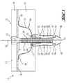
- the fastening device 11 With the fastening device 11 shown in FIGS. 1 to 3, solar panels 1 are fastened to a mounting rail 2, which has a mounting opening 3 limited by edges 4.
- the fastening device 11 comprises a hold-down element 12 for holding down the solar panels 1, a threaded rivet as a nut element 21 for clamping the fastening device 11 to the mounting rail 2 and a fastening screw 22.
- the fastening screw 22 has as an engaging means 23 a hexagon socket and a screw shank 24, starting from its free end 25, at least partially provided with an external thread. Due to the longitudinal extent of the fastening screw 22, a longitudinal axis 26 of the fastening device 11 extends.
- the hold-down element 12 has two opposing hold-down portions 13 which come into abutment with the solar panels 1 in the clamped state of the fastening device 11, a spacer portion 14 which is provided with a passage opening 15 for the fastening screw 22, and respectively the spacer portion 14 with the hold-down portions 13th connecting sections 16 on. Further, the hold-down element 12 is provided with two side walls 17 aligned parallel to one another, which extend on the side of the spacer section 14 facing away from the hold-down sections 13.
- the fastening device 11 further comprises a made of a spring steel in a stamping / bending process, substantially U-shaped connecting element 31, which has a connecting portion 32 and two projecting resilient portions 33 thereof, in the relaxed state of the connecting element 31 substantially parallel to the longitudinal axis 26 of the fastening device 11 extend. Between the resilient portions 33, a gap 36 is formed. At its end region, the resilient sections 33 have a first receiving space 37 for receiving in portions the edges 4 of the mounting opening 3, which is formed by a holding portion 34 and a projection 35 spaced from the holding portion 34 in the direction of the connecting portion 32. The holding portion 34 and the projection 35 are arranged on the side facing away from the gap 36 side 38 of the resilient portions 33.
- the projection 35 extends in the direction of the connecting portion 32 and thereby forms a second receiving space 39 for a portion of the screw shaft 24 of the fastening screw 22, which extends from the free end 25 of the screw shaft 24.
- the free edge of the projections 35 creates a sufficient bearing surface of the connecting element 31 on the outside 5 of the mounting rail 2.
- insertion portions 40 are provided, which protrude from the holding portions 34 facing each other and a conical tip as an insertion aid for Form fastening device 11.
- the fastening device 11 a leaf spring 47 as a spring element 46, which on the one hand with a central portion 48 which is fixed to the nut member 21, on the nut member 21 and on the other hand with the free ends 49 of the leaf spring 47 at the spacer portion 14 of the hold-down element 12th supported.
- FIGS. 2 a to 2 c the mounting operation for fixing solar panels 1 to the mounting rail 2 with the fastening device 11 will be described.
- the solar panels 1 are laid at a distance from each other on a grid created with the mounting rails 2.
- the fastening device 11 between two solar panels 1 in the direction of the arrow 51 is inserted (Fig. 2a).
- the resilient portions 33 of the connecting element 31 are compressed, wherein the free end 25 of the fastening screw 22 in the second, of the projections 35, in the direction extending the connecting portion 32, formed receiving space 39 is received.
- the connecting element 31 snaps in and the edges 4 of the mounting opening 3 are received by the first receiving spaces 37 (FIG. 2 b), whereby the fastening device 11 moves along the mounting opening 3 slidably held on the mounting rail 2.
- the fastening device 11 is clamped to the mounting rail 2 by actuating the fastening screw 22 (FIG. 2c).
- the hold-down element 12 is moved counter to the spring force of the leaf spring 47 in the direction of the mounting rail 2 until the hold-down sections 13 of the hold-down element 12 come into contact with the solar panels.
- the free end 25 of the screw shaft 24 penetrates during bracing between the resilient portions 33 in the mounting hole 3, wherein the resilient portions 33 are pressed against the edges 4 of the mounting hole 3.
- the solar panels 1 are fixed with the inventive fastening device 11 against tensile and compressive stress on the mounting rail 2.
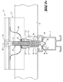
- the fastening device 61 shown in Fig. 4 differs from the fastening device 11 in particular by the configuration of the spring element 66.
- the spring element 66 is formed as a compression spring 67 which is supported on the one hand on the nut member 71 and on the other hand on the spacer portion 74 of the hold-down element 72.
- the fastening screw 62 is passed through the compression spring 67.
- a sheet metal section 69 is provided with angled edges between the side walls 77 of the hold-down element 72.
Landscapes
- Engineering & Computer Science (AREA)
- General Engineering & Computer Science (AREA)
- Mechanical Engineering (AREA)
- Physics & Mathematics (AREA)
- Life Sciences & Earth Sciences (AREA)
- Sustainable Development (AREA)
- Sustainable Energy (AREA)
- Thermal Sciences (AREA)
- Chemical & Material Sciences (AREA)
- Combustion & Propulsion (AREA)
- Roof Covering Using Slabs Or Stiff Sheets (AREA)
- Connection Of Plates (AREA)
Applications Claiming Priority (1)
| Application Number | Priority Date | Filing Date | Title |
|---|---|---|---|
| DE102005000129A DE102005000129A1 (de) | 2005-09-23 | 2005-09-23 | Befestigungsvorrichtung für die Befestigung von Solarpaneelen an einer Montageschiene |
Publications (2)
| Publication Number | Publication Date |
|---|---|
| EP1767793A2 true EP1767793A2 (fr) | 2007-03-28 |
| EP1767793A3 EP1767793A3 (fr) | 2012-09-19 |
Family
ID=37450867
Family Applications (1)
| Application Number | Title | Priority Date | Filing Date |
|---|---|---|---|
| EP06120779A Withdrawn EP1767793A3 (fr) | 2005-09-23 | 2006-09-15 | Dispositif de fixation pour la fixation des panneaux solaires à un rail d'assemblage |
Country Status (2)
| Country | Link |
|---|---|
| EP (1) | EP1767793A3 (fr) |
| DE (1) | DE102005000129A1 (fr) |
Cited By (11)
| Publication number | Priority date | Publication date | Assignee | Title |
|---|---|---|---|---|
| DE202011003490U1 (de) | 2011-03-04 | 2011-05-12 | Sodeik, Clemens | Halteklammer |
| CN102169914A (zh) * | 2011-03-30 | 2011-08-31 | 厦门天环能源科技有限公司 | 太阳能电池板安放结构 |
| FR2957405A1 (fr) * | 2010-03-10 | 2011-09-16 | Altus Energy | Dispositif d'installation de panneaux solaires |
| EP2410190A1 (fr) * | 2010-07-21 | 2012-01-25 | Fath Solar Group Holding GmbH | Dispositif de fixation d'un objet à un élément présentant une ouverture aux bords marqués |
| EP2029946B1 (fr) * | 2006-06-15 | 2012-05-16 | Haticon GmbH | Système de montage, en particulier pour modules solaires |
| EP2476972A1 (fr) * | 2011-01-17 | 2012-07-18 | PAIRAN GmbH | Dispositif de fixation et coulisseau pour la fixation de modules photovoltaïques |
| DE102012105072B3 (de) * | 2012-06-12 | 2013-11-28 | Hanwha Q.CELLS GmbH | Verfahren zum Montieren mindestens eines Solarmoduls und Solarmodulanordnung |
| EP2669595A2 (fr) | 2012-06-01 | 2013-12-04 | HILTI Aktiengesellschaft | Dispositif de fixation pour panneaux solaires |
| CN103647503A (zh) * | 2013-12-13 | 2014-03-19 | 保定天威英利新能源有限公司 | 一种可自动定位光伏组件及其安装方法 |
| ITBS20130098A1 (it) * | 2013-07-08 | 2015-01-09 | Ambrosia Holding S R L | Dispositivo di fissaggio per pannelli solari o fotovoltaici |
| WO2017148786A1 (fr) * | 2016-03-03 | 2017-09-08 | Hella Kgaa Hueck & Co. | Dispositif de liaison pour la liaison avec maintien de deux éléments l'un par rapport à l'autre |
Families Citing this family (4)
| Publication number | Priority date | Publication date | Assignee | Title |
|---|---|---|---|---|
| DE102007016047B4 (de) * | 2007-03-30 | 2011-08-25 | HatiCon GmbH, 16303 | Befestigungseinrichtung für Solarmodule |
| DE102010049229A1 (de) * | 2010-10-25 | 2012-04-26 | Juwi R & D Research Development Gmbh & Co. Kg | Gestell |
| DE102015013262B3 (de) | 2015-10-06 | 2017-01-12 | Lutz Wolff | Montagesystem für plattenförmige Körper, insbesondere Solarmodule |
| DE102020110550B4 (de) | 2020-04-17 | 2025-11-13 | Ibc Solar Ag | Modulklemme, Verfahren zur Befestigung von Solarmodulen, Verbindungsanordnung zur Befestigung eines Solarmoduls und Anordnung mit Verbindungsanordnung und Solarmodul |
Family Cites Families (5)
| Publication number | Priority date | Publication date | Assignee | Title |
|---|---|---|---|---|
| CH418735A (de) * | 1963-01-24 | 1966-08-15 | Glissa Ag | Befestigungsknopf für Leisten |
| DE29616947U1 (de) * | 1996-09-28 | 1997-03-27 | Leichtmetallbau Schletter GmbH, 83527 Haag | Befestigungssystem für Photovoltaikpaneele |
| DE29713037U1 (de) * | 1997-07-23 | 1997-09-25 | Pfitzmann, Wolfgang, 21339 Lüneburg | Befestigungsanordnung für die Anbringung eines Bauteils an einer C-förmigen Halteschiene |
| US6672018B2 (en) * | 2001-10-12 | 2004-01-06 | Jefferson Shingleton | Solar module mounting method and clip |
| DE10305610A1 (de) * | 2003-02-11 | 2004-08-19 | Ejot Gmbh & Co. Kg | Kunststoffmutter zur Aufnahme an einem einen Durchbruch aufweisenden Bauteil |
-
2005
- 2005-09-23 DE DE102005000129A patent/DE102005000129A1/de not_active Withdrawn
-
2006
- 2006-09-15 EP EP06120779A patent/EP1767793A3/fr not_active Withdrawn
Cited By (16)
| Publication number | Priority date | Publication date | Assignee | Title |
|---|---|---|---|---|
| EP2029946B1 (fr) * | 2006-06-15 | 2012-05-16 | Haticon GmbH | Système de montage, en particulier pour modules solaires |
| US8936224B2 (en) | 2006-06-15 | 2015-01-20 | Sapa Holding Gmbh | Mounting system, especially for solar modules |
| FR2957405A1 (fr) * | 2010-03-10 | 2011-09-16 | Altus Energy | Dispositif d'installation de panneaux solaires |
| EP2410190A1 (fr) * | 2010-07-21 | 2012-01-25 | Fath Solar Group Holding GmbH | Dispositif de fixation d'un objet à un élément présentant une ouverture aux bords marqués |
| EP2476972A1 (fr) * | 2011-01-17 | 2012-07-18 | PAIRAN GmbH | Dispositif de fixation et coulisseau pour la fixation de modules photovoltaïques |
| DE202011003490U1 (de) | 2011-03-04 | 2011-05-12 | Sodeik, Clemens | Halteklammer |
| EP2495508A2 (fr) | 2011-03-04 | 2012-09-05 | Clemens Sodeik | Clip de maintien |
| CN102169914A (zh) * | 2011-03-30 | 2011-08-31 | 厦门天环能源科技有限公司 | 太阳能电池板安放结构 |
| EP2669595A2 (fr) | 2012-06-01 | 2013-12-04 | HILTI Aktiengesellschaft | Dispositif de fixation pour panneaux solaires |
| DE102012209272A1 (de) | 2012-06-01 | 2013-12-05 | Hilti Aktiengesellschaft | Befestigungsvorrichtung für Solarpaneele |
| EP2669595A3 (fr) * | 2012-06-01 | 2014-07-09 | HILTI Aktiengesellschaft | Dispositif de fixation pour panneaux solaires |
| DE102012105072B3 (de) * | 2012-06-12 | 2013-11-28 | Hanwha Q.CELLS GmbH | Verfahren zum Montieren mindestens eines Solarmoduls und Solarmodulanordnung |
| ITBS20130098A1 (it) * | 2013-07-08 | 2015-01-09 | Ambrosia Holding S R L | Dispositivo di fissaggio per pannelli solari o fotovoltaici |
| CN103647503A (zh) * | 2013-12-13 | 2014-03-19 | 保定天威英利新能源有限公司 | 一种可自动定位光伏组件及其安装方法 |
| WO2017148786A1 (fr) * | 2016-03-03 | 2017-09-08 | Hella Kgaa Hueck & Co. | Dispositif de liaison pour la liaison avec maintien de deux éléments l'un par rapport à l'autre |
| DE102016103783B4 (de) * | 2016-03-03 | 2025-07-17 | HELLA GmbH & Co. KGaA | Verbindungseinrichtung zur haltenden Verbindung von zwei Bauteilen zueinander |
Also Published As
| Publication number | Publication date |
|---|---|
| EP1767793A3 (fr) | 2012-09-19 |
| DE102005000129A1 (de) | 2007-03-29 |
Similar Documents
| Publication | Publication Date | Title |
|---|---|---|
| EP2435768B1 (fr) | Dispositif servant à fixer un rail de montage sur une tige filetée | |
| EP2013493B1 (fr) | Dispositif de fixation | |
| DE10357844B4 (de) | Befestigungssystem | |
| EP3472403B1 (fr) | Dispositif servant à fixer un élément en forme de plaque dans une rainure de réception d'un rail de support | |
| EP2481939B1 (fr) | collier de serrage | |
| EP3423745B1 (fr) | Collier profilé | |
| EP0805297B1 (fr) | Dispositif d'ancrage | |
| EP1826507A2 (fr) | Dispositif de fixation pour la fixation de panneaux solaires sur un rail de montage | |
| EP3308066B1 (fr) | Bride pourvue d'une bande de bride et d'un dispositif de pré-positionnement | |
| DE4447456C2 (de) | Montageschiene | |
| DE102012221228A1 (de) | Toleranzausgleichsvorrichtung | |
| EP2527762A1 (fr) | Dispositif de fixation | |
| DE102005000129A1 (de) | Befestigungsvorrichtung für die Befestigung von Solarpaneelen an einer Montageschiene | |
| EP3623721A1 (fr) | Crochet de toit | |
| EP3623722A1 (fr) | Crochet de toit | |
| DE102006000090A1 (de) | Befestigungsvorrichtung für ein Trägerprofil | |
| EP2292988A2 (fr) | Dispositif de fixation pour la fixation de panneaux solaires sur un rail de montage | |
| EP1767719A2 (fr) | Dispositif de fixation pour fixer des panneaux solaires à un rail de montage en forme de C. | |
| DE19946890C2 (de) | Halteelement zur unverlierbaren Halterung von Kopfschrauben | |
| DE102020110550A1 (de) | Modulklemme, Verfahren zur Befestigung von Solarmodulen, Verbindungsanordnung zur Befestigung eines Solarmoduls und Anordnung mit Verbindungsanordnung und Solarmodul | |
| EP2322874A1 (fr) | Crochet de toit | |
| DE19652027C2 (de) | Montageschiene zur Befestigung von Rohren o. dgl. Gegenständen | |
| DE19903972C2 (de) | Federmutter zur Schnellbefestigung | |
| DE20108139U1 (de) | Klemmvorrichtung | |
| DE102008046181A1 (de) | Antennenhalter für eine Satellitenschüssel |
Legal Events
| Date | Code | Title | Description |
|---|---|---|---|
| PUAI | Public reference made under article 153(3) epc to a published international application that has entered the european phase |
Free format text: ORIGINAL CODE: 0009012 |
|
| AK | Designated contracting states |
Kind code of ref document: A2 Designated state(s): AT BE BG CH CY CZ DE DK EE ES FI FR GB GR HU IE IS IT LI LT LU LV MC NL PL PT RO SE SI SK TR |
|
| AX | Request for extension of the european patent |
Extension state: AL BA HR MK YU |
|
| RIN1 | Information on inventor provided before grant (corrected) |
Inventor name: RUBIO, DANIEL Inventor name: HOFFMANN, ARMIN |
|
| PUAL | Search report despatched |
Free format text: ORIGINAL CODE: 0009013 |
|
| AK | Designated contracting states |
Kind code of ref document: A3 Designated state(s): AT BE BG CH CY CZ DE DK EE ES FI FR GB GR HU IE IS IT LI LT LU LV MC NL PL PT RO SE SI SK TR |
|
| AX | Request for extension of the european patent |
Extension state: AL BA HR MK RS |
|
| RIC1 | Information provided on ipc code assigned before grant |
Ipc: F24J 2/52 20060101ALI20120810BHEP Ipc: F16B 5/02 20060101ALI20120810BHEP Ipc: F16B 5/06 20060101AFI20120810BHEP |
|
| 17P | Request for examination filed |
Effective date: 20130319 |
|
| AKX | Designation fees paid |
Designated state(s): AT BE BG CH CY CZ DE DK EE ES FI FR GB GR HU IE IS IT LI LT LU LV MC NL PL PT RO SE SI SK TR |
|
| STAA | Information on the status of an ep patent application or granted ep patent |
Free format text: STATUS: THE APPLICATION IS DEEMED TO BE WITHDRAWN |
|
| 18D | Application deemed to be withdrawn |
Effective date: 20150401 |