EP1767863A2 - Appareil de cuisson à encastrer en hauteur - Google Patents
Appareil de cuisson à encastrer en hauteur Download PDFInfo
- Publication number
- EP1767863A2 EP1767863A2 EP20060120425 EP06120425A EP1767863A2 EP 1767863 A2 EP1767863 A2 EP 1767863A2 EP 20060120425 EP20060120425 EP 20060120425 EP 06120425 A EP06120425 A EP 06120425A EP 1767863 A2 EP1767863 A2 EP 1767863A2
- Authority
- EP
- European Patent Office
- Prior art keywords
- air
- cooking appliance
- appliance according
- fan
- space
- Prior art date
- Legal status (The legal status is an assumption and is not a legal conclusion. Google has not performed a legal analysis and makes no representation as to the accuracy of the status listed.)
- Withdrawn
Links
- 238000010411 cooking Methods 0.000 title claims description 63
- 238000009423 ventilation Methods 0.000 claims description 49
- 238000009434 installation Methods 0.000 claims description 26
- 238000000034 method Methods 0.000 claims description 7
- 238000007599 discharging Methods 0.000 claims description 2
- 238000013022 venting Methods 0.000 claims 1
- 238000001816 cooling Methods 0.000 description 18
- 238000010438 heat treatment Methods 0.000 description 13
- 238000013461 design Methods 0.000 description 7
- 238000009413 insulation Methods 0.000 description 6
- 239000002241 glass-ceramic Substances 0.000 description 5
- 230000004913 activation Effects 0.000 description 3
- 230000000712 assembly Effects 0.000 description 3
- 238000000429 assembly Methods 0.000 description 3
- 230000002349 favourable effect Effects 0.000 description 3
- 238000005259 measurement Methods 0.000 description 3
- 238000003825 pressing Methods 0.000 description 3
- 238000006243 chemical reaction Methods 0.000 description 2
- 238000012790 confirmation Methods 0.000 description 2
- 238000009826 distribution Methods 0.000 description 2
- 230000006870 function Effects 0.000 description 2
- 239000011810 insulating material Substances 0.000 description 2
- 230000002045 lasting effect Effects 0.000 description 2
- 238000000197 pyrolysis Methods 0.000 description 2
- 230000000630 rising effect Effects 0.000 description 2
- 238000003860 storage Methods 0.000 description 2
- 238000005299 abrasion Methods 0.000 description 1
- 229910052782 aluminium Inorganic materials 0.000 description 1
- XAGFODPZIPBFFR-UHFFFAOYSA-N aluminium Chemical compound [Al] XAGFODPZIPBFFR-UHFFFAOYSA-N 0.000 description 1
- 230000001174 ascending effect Effects 0.000 description 1
- 230000005540 biological transmission Effects 0.000 description 1
- 238000004140 cleaning Methods 0.000 description 1
- 238000004891 communication Methods 0.000 description 1
- 238000010276 construction Methods 0.000 description 1
- 238000005034 decoration Methods 0.000 description 1
- 230000001419 dependent effect Effects 0.000 description 1
- 238000011161 development Methods 0.000 description 1
- 238000010586 diagram Methods 0.000 description 1
- 238000006073 displacement reaction Methods 0.000 description 1
- 230000009977 dual effect Effects 0.000 description 1
- 238000011156 evaluation Methods 0.000 description 1
- 230000006698 induction Effects 0.000 description 1
- 238000002347 injection Methods 0.000 description 1
- 239000007924 injection Substances 0.000 description 1
- 238000003780 insertion Methods 0.000 description 1
- 230000037431 insertion Effects 0.000 description 1
- 239000000463 material Substances 0.000 description 1
- 239000012528 membrane Substances 0.000 description 1
- 229910052751 metal Inorganic materials 0.000 description 1
- 239000002184 metal Substances 0.000 description 1
- 230000007935 neutral effect Effects 0.000 description 1
- 230000003287 optical effect Effects 0.000 description 1
- 238000005192 partition Methods 0.000 description 1
- 239000004065 semiconductor Substances 0.000 description 1
- 125000006850 spacer group Chemical group 0.000 description 1
- 238000009827 uniform distribution Methods 0.000 description 1
- 238000010792 warming Methods 0.000 description 1
Images


Classifications
-
- F—MECHANICAL ENGINEERING; LIGHTING; HEATING; WEAPONS; BLASTING
- F24—HEATING; RANGES; VENTILATING
- F24C—DOMESTIC STOVES OR RANGES ; DETAILS OF DOMESTIC STOVES OR RANGES, OF GENERAL APPLICATION
- F24C15/00—Details
- F24C15/006—Arrangements for circulation of cooling air
-
- F—MECHANICAL ENGINEERING; LIGHTING; HEATING; WEAPONS; BLASTING
- F24—HEATING; RANGES; VENTILATING
- F24C—DOMESTIC STOVES OR RANGES ; DETAILS OF DOMESTIC STOVES OR RANGES, OF GENERAL APPLICATION
- F24C15/00—Details
- F24C15/02—Doors specially adapted for stoves or ranges
- F24C15/027—Doors specially adapted for stoves or ranges located at bottom side of housing
-
- F—MECHANICAL ENGINEERING; LIGHTING; HEATING; WEAPONS; BLASTING
- F24—HEATING; RANGES; VENTILATING
- F24C—DOMESTIC STOVES OR RANGES ; DETAILS OF DOMESTIC STOVES OR RANGES, OF GENERAL APPLICATION
- F24C15/00—Details
- F24C15/32—Arrangements of ducts for hot gases, e.g. in or around baking ovens
- F24C15/322—Arrangements of ducts for hot gases, e.g. in or around baking ovens with forced circulation
Definitions
- the present invention relates to a high-installation cooking appliance having at least one housing body with a muffle defining a cooking space, a housing cover for covering the housing body so that at least one gap between the housing body and the housing cover is formed, and with a vent for discharging air from the at least one gap to the outside.
- the present invention further relates to an associated method of operation.
- Such a generic high-installation cooking appliance is off US 2,944,540 known, in which the intermediate space is designed so that located in the muffle air - especially hot air - freely emerge from the underlying muffle opening, ascend through heat convection through the gap up to an air outlet and can escape through this outwards.
- the purpose of the space is the improved thermal insulation of the muffle, as the temperature gradient is reduced to muffle by the rising warm air.
- the disadvantage is that rising hot air, although better insulated the muffle, but the temperature of the device around the muffle to rise. For household appliances, this is disadvantageous in terms of user safety (burns) and reliability and service life (heating of functional parts, in particular electronic components).
- a disadvantage of these cooking appliances is that the ventilation devices are designed for cooking appliances equipped with baking car, while they are not suitable for high-installation cooking appliances due to the cramped construction.
- the present object is achieved by the high-mounting cooking appliance with the features of claim 1 and a method according to claim 17.
- Advantageous embodiments are the dependent claims individually or in combination removed.
- the high-installation cooking appliance is equipped with a ventilation opening for supplying air from the outside into the at least one intermediate space, as well as with at least one ventilation device for generating an air flow from the ventilation opening to the ventilation opening.
- a ventilation opening for supplying air from the outside into the at least one intermediate space
- at least one ventilation device for generating an air flow from the ventilation opening to the ventilation opening.
- the design of the gap is initially not essential; it may contain various elements (eg spacers, baffles, cables, etc.) as long as only the desired ventilation is achieved.
- not all sides of the cooking device must be equipped with a gap, and also does not have to be ventilated every gap.
- the number and arrangement of the radiator, intake and / or intake is not limited. For example, in each case a separate fan for a Wrasenö réelle or a Wrasenauslass, a ventilation of a front gap and be provided for electronics.
- the temperature reduction can, for example, via an adjustment of the ventilation performance of the ventilation device, a steering of the air flows, a flow cross-section u. v. m. happen.
- Several intermediate spaces may be fluidically related.
- a sufficient insulation of the muffle can be achieved, for example, by suitable insulating materials between the housing body and muffle frame, at least in some areas, which is also energy efficient.
- At least one ventilatable intermediate space is the front intermediate space which is delimited at least partially by a first, inner viewing window and a further viewing window.
- the viewing window or windows are those surface elements that are less thermally insulating compared to special insulation and thus potentially more heat.
- the front gap comprises at least a first front gap between a first, inner viewing window and a second, middle viewing window, and a second, front gap between a second, middle viewing window and a third, outer viewing window. These spaces run in a vertical direction substantially parallel.
- the object can be achieved by a single, correspondingly designed suction opening, it is advantageous for effective large-area cooling if the at least one ventilation device is equipped with at least two suction openings.
- different types of intake for example with respect to temperature, air quality
- the ventilation device comprises exactly one fan, possibly connected to a plurality of suction ports.
- the plurality of intake openings may for example be introduced in a single intake pipe, which leads to an intake opening of the fan.
- the fan is conveniently a double fan, in particular a double-radial fan, which has two intake openings, in particular in the opposite direction facing suction.
- double fans two part fans are driven together and suck in air through each of the intake ports.
- the part fans may be the same or different, z. B. with different ventilation performance.
- the resulting exhaust air can be mixed or dispensed substantially separately for each part fan.
- the at least one ventilation device is advantageously provided with at least two suction openings equipped, one of which opens to the front gap.
- one of the intake openings sucks at least partially, in particular mainly, cooling air through the front intermediate space.
- At least one of the suction openings may open to the gap between the surface of the housing body and the housing cover.
- air is sucked in from the intermediate spaces, in particular the lateral and / or the rear intermediate space, over the surface of the housing body.
- Such an air flow cools both the vented spaces and the surface of the housing body and attached components such.
- the ventilation device in particular the fan, especially the double fan, is arranged on the surface of the housing body, and one of the suction openings is connected to a leading to the front space intake port. Through the intake passage, a sufficient suction power in the front space and thus sufficient cooling of the front gap is ensured.
- the double fan with a - typically leading to the vent opening - exhaust duct which contains a flow divider for separating the substantially unmixed exhaust air from the two intake ports of the double fan at least over the length of the flow divider.
- a flow divider for separating the substantially unmixed exhaust air from the two intake ports of the double fan at least over the length of the flow divider.
- In the part of the exhaust duct, which leads substantially not sucked from the front space - warmer - air leads are at least one inlet air channel and an outlet air channel are arranged, which lead to the lamp and cool it with the exhaust air.
- the intake duct of the ventilation device in addition to the front gap also sucks air from an open Wrasenauslass.
- the air mixed with vapors is discharged directly to the outside, while the clean air can cool a luminaire.
- the vapor opening can be closed by at least one vapor valve.
- the vapor valve is arranged and dimensioned so that it can - depending on the opening or closing state - change the flow cross section between the front gap and fan; This will z. B. the ventilation through the front gap stronger (with closed vents flap) or weaker (with open vents flap, which then sets up in the flow channel).
- the at least one ventilation opening in the region of the underside of the housing - the housing cover and / or the housing body - is mounted, in particular on the bottom itself. It is advantageous to provide a plurality of ventilation openings.
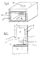
- FIG. 1 shows a high-installation cooking appliance with a housing 1 is shown.
- the back of the housing 1 is mounted on a wall 2 in the manner of a hanging cabinet.
- a cooking chamber 3 is defined, which can be controlled via a front side in the housing 1 introduced viewing window 4.
- FIG. 4 it can be seen that the cooking space 3 is delimited by a muffle 5, which is provided with a heat-insulating sheath, not shown, and that the muffle 5 has a bottom-side muffle opening 6.
- the muffle opening 6 is closable with a bottom door 7.
- the bottom door 7 is shown lowered, being with its underside in contact with a worktop 8 a kitchen device. In order to close the cooking chamber 3, the bottom door 7 is in the position shown in FIG.
- the drive device 9, 10 has a drive motor 9 shown in dashed lines in FIGS. 1, 2 and 4, which is arranged between the muffle 5 and an outer wall of the housing 1.
- the drive motor 9 is arranged in the region of the rear side of the housing 1 and is, as shown in FIGS. 1 or 4, in operative connection with a pair of lifting elements 10, which are connected to the bottom door 7.
- each lifting element 10 is designed as an L-shaped carrier, whose vertical leg extends from the housing-side drive motor 9
- the drive motor 9 can be actuated by means of a control panel 12 and a control circuit 13, which is arranged according to FIGS. 1 and 2 at the front of the bottom door 7.
- the control circuit 13 is located behind the control panel 12 within the bottom door 7.
- the control circuit 13, which consists of several spatially and functionally separated and over a communication bus communicating circuit boards composed, represents a central control unit for the device operation and controls and / or regulates z.
- a heating a method of the bottom door 3, a conversion of user input, a lighting, a pinch protection, a clocking of the radiator 16, 17, 18, 22 and much more.
- FIG. 1 shows that an upper side of the bottom door 7 has a hob 15. Almost the entire surface of the hob 15 is occupied by radiators 16, 17, 18, which are indicated in phantom in Fig. 1.
- the radiator 16, 17 are two spaced apart, different sized cooking hob, while the radiator 18 is provided between the two cooking area heaters 16,17 surface heating element, which almost encloses the cooking area heaters 16, 17.
- the hotplate heaters 16, 17 define for the user associated cooking zones or hobs; the hotplate heaters 16, 17 together with the surface heating element 18 define a bottom heat zone. The zones may be indicated by a suitable decoration on the surface.
- the radiators 16, 17, 18 are each controlled via the control circuit 13.
- the radiators 16, 17, 18 are configured as radiant heaters, which are covered by a glass ceramic plate 19.
- the glass ceramic plate 19 has approximately the dimensions of the top of the bottom door 7.
- the glass ceramic plate 19 is further equipped with mounting holes (not shown) through the base for holding support members 20 for Garguta 21 protrude, as shown in Fig. 4.
- mounting holes not shown
- a glass ceramic plate 19 other - preferably quick-responding - covers can be used, for. B. a thin sheet.
- the high-installation cooking appliance can be switched to a cooking or a bottom heat mode, which will be explained below.
- the cooking surface heaters 16, 17 can be controlled individually by means of control elements 11, which are provided in the control panel 12, via the control circuit 13, while the surface heating element 18 remains out of operation.
- the hotplate mode is executable with the bottom door 7 lowered, as shown in Fig. 1. But it can also be operated with closed cooking chamber 3 with raised floor door 7 in an energy saving function.
- the cooking surface 15 providing the bottom heat has a uniform distribution of the heat output over the surface of the hob 15, although the heating elements 16, 17, 18 have different nominal powers.
- the radiators 16, 17, 18 are not switched by the control circuit 13 to a continuous operation, but the power supply to the radiators 16, 17, 18 is clocked.
- the different sized nominal heating powers of the radiator 16, 17, 18 are individually reduced so that the radiators 16, 17, 18 provide a uniform over the surface of the hob 15 distribution of the heat output.
- Fig. 3 shows schematically the position of a circulating air pot 23 with a circulating air motor and an associated ring radiator, z. B. for generating hot air in a hot air operation.
- the open to the cooking chamber 3 Um Kunststofftopf 23 is separated from this typically by a baffle (not shown).
- a mounted on an upper side of the muffle 5 Oberhitzemos stresses 22 is provided, the single-circuit or Geographic Vietnamese Republicig, z. B. with an inner and an outer circle, can be executed.
- the various operating modes such as, for example, top heat, hot air or Schnellauffilter compassion, by an appropriate activation and adjustment of the heating power of the radiator 16, 17, 18, 22, possibly with activation of the fan 23, are set.
- the adjustment of the heating power can be done by appropriate timing.
- the hob 15 can also be designed differently, for. B. with or without roasting zone, as a pure - one or Moika - warming zone without cooktops and so on.
- the housing 1 has a seal 24 towards the bottom door 7.
- the control panel 12 is arranged mainly at the front of the bottom door 7. There are alternatively other arrangements conceivable, for. B. at the front of the housing 1, divided into different sub-fields and / or partially Side surfaces of the cooking appliance. Further designs are possible.
- the controls 11 are not limited in their design and can, for. B. z. As control knob, toggle switch, pushbuttons and membrane keys include the display elements 14 include z. B. LED, LCD and / or touchscreen displays.
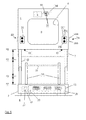
- Fig. 5 is schematically and not to scale a high-mounted cooking appliance shown from the front, in which the bottom door 7 is open on contact with the worktop 8. The closed state is shown in dashed lines.
- each traversing panel 25 comprises two pushbuttons, namely an upper CLOSE button 25a for a bottom door 7 traveling upwards in the closing direction and a lower OPEN button 25b for one Without automatic operation (see below) moves the bottom door 7 only by continuous simultaneous pressing the CLOSE buttons 25a both traversing panels 25 upwards, if possible; also moves the bottom door 7 only by continuous simultaneous pressing of the UP buttons 25b both traversing panels 25 down, if possible (manual operation). Since in manual operation an increased operator attention of the user is given and also both hands are used here, an anti-trap is then optional.
- traversing panels 26 are mounted on opposite outer sides of the housing 1 with corresponding ZU buttons 26a and UP buttons 26b, as shown in dotted lines.
- the control circuit 13 comprises a memory unit 27 for storing at least one destination or travel position P0, P1, P2, PZ of the bottom door 7, preferably with volatile memory components, eg. B. DRAMs. If a target position P0, P1, P2, PZ is stored, the bottom door can move independently after actuation of one of the keys 25a, 25b and 26a, 26b of the traversing panels 25 and 26 in the set direction until the next target position is reached or one of the buttons 25a, 25b and 26a, 26b again is pressed (automatic mode). In this embodiment, the lowest target position PZ corresponds to the maximum opening, the (zero) position P0 corresponds to the closed state, and P1 and P2 are freely adjustable intermediate positions.
- the lowest target position PZ corresponds to the maximum opening
- the (zero) position P0 corresponds to the closed state
- P1 and P2 are freely adjustable intermediate positions.
- Automatic mode and manual operation are not mutually exclusive: by permanently actuating the positioning panel (s) 25, 26, the bottom door 7 also moves in manual mode if a target position could be approached in this direction. It can be z. B. a maximum actuation time of the traversing fields 25 and 26, respectively, of the associated keys 25a, 25b and 26a, 26b, are set to activate the automatic mode, z. B. 0.4 seconds.
- a target position P0, P1, P2, PZ may be any position of the bottom door 7 between and including the zero position P0 and the maximum open position PZ.
- the maximum stored opening position PZ need not be the position with abutment on the work surface 8.
- Storing the target position P0, P1, P2, PZ can with the bottom door 7 at the desired target position P0, P1, P2, PZ, by, for example, lasting several seconds (eg, lasting two seconds), pressing a confirmation key 28 in the control panel 12th be performed.
- Existing optical and / or acoustic signal transmitters which output corresponding signals after storing a target position are not shown for the sake of clarity.
- a start-up of the desired target position P0, P1, P2, PZ to be set takes place, for example, by - in this embodiment - ambidextrous operation of the movement panels 25 or 26 and manual method to this position.
- target positions P0, P1, P2, PZ these can be approached successively by actuating the corresponding travel keys 25a, 25b or 26a, 26b.
- the target position (s) are advantageously erasable and / or overwritten.
- only one target position can be stored in the opened state, while the zero position P0 is automatically recognized and can be approached automatically.
- the zero position P0 must be stored in order to be automatically approachable.
- the or a target position P1, P2, PZ opens the bottom door 7 at least about 400 mm to about 540 mm (ie P1-P0, P2-P0, PZ-P0 ⁇ 40cm to 54 cm). In this opening dimension the food supports 21 are easy to insert into the support members 20. It is advantageous if the viewing window 4 is mounted approximately at eye level of the user or slightly below, z. B. by means of a template that indicates the dimensions of the cooking appliance.
- the drive motor 9 from FIG. 1 has at least one sensor unit 31, 32 arranged on a motor shaft 30, possibly in front of or behind a transmission, in order to measure a travel path or a position and / or a speed of the bottom door 7.
- the sensor unit may include one or more induction, reverberation, opto, SAW sensors, and so forth.
- two Hall (part) elements 31 offset by 180 ° - ie opposite - attached to the motor shaft 30, and a Hallmeßaufillon 32 is fixedly mounted at this area of the motor shaft spaced. If a Hall element 31 then moves past the measuring transducer 32 when the motor shaft 30 rotates, a measuring or sensor signal is generated which is, to a good approximation, digital.
- a speed control can realize the speed, for example via a PWM-controlled power semiconductor.
- the distance measurement is automatically re-adjusted by initialization in the zero position P0 of the bottom door 7 at each start, so z.
- a faulty sensor signal output or recording is not traditional.
- the drive motor 9 is operated by actuation of both traversing panels 25 and 26, even when the main switch 29 is turned off.
- control circuit 13 is flexible and not limited, so it can be several boards, z. B. include a display board, a control board and an elevator board, which are spatially separated.
- a 4 mm opening dimension can be detected by limit switches 33, which deactivate anti-pinch protection when actuated.
- the high-installation cooking appliance can also be designed without a storage unit 27, in which case no automatic operation is possible. This can be for increased operating safety, eg. B. as protection against pinching, be useful.
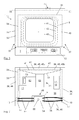
- Fig. 6 shows schematically (not to scale) indicated from the front, the position of individual elements of the housing 1 in the closed state, in which the bottom door 7 on the muffle 5 final touches and thereby the housing 1 visually terminates.
- the housing 1 consists of an (inner) housing body 34 (shown in dashed lines) and a housing cover or cover 35, which surrounds the housing body 34 at least front and side.
- the gap 36 between the housing body 34 and housing cover 35 is designed so that cooling air can flow at least partially.
- These are in the housing cover 35 lower ventilation holes 37, z.
- As ventilation slots provided which are mounted lower than the upper surface 38 of the housing body 34, preferably in an area in the vicinity of the muffle opening or the lift floor 7.
- the ventilation openings 37 are here introduced at the bottom of the housing cover 35; but can also be present for example laterally. Accordingly, there are one or more upper vents 39, z. B. a vent slot in the upper part of the housing cover 35, especially in the ceiling. Thereby, an air flow of cooling air through the gap 36 can be constructed, typically from bottom to top, which is then discharged through the ceiling.
- the muffle 5 (dotted drawn) is introduced, the associated space 40 - is lined - with the exception of the front - with insulating material.
- the muffle 5 is conversely configured U-shaped.
- a plurality of viewing windows 4 are present, namely a muffle 5 directly covering the first (inner) window 41 (dash-dotted lines), which therefore at least partially represents a wall of the muffle 5, further through the housing body 34th held second (middle) window 42 (also indicated by dash-dotted lines) and a third (outer) viewing window 43 in the housing cover 35th
- additional intermediate windows can be drawn in (not shown), which are preferably fastened to the housing body 34, or fewer viewing windows 4 may be present, eg. B. only the inner and outer windows 41, 43.
- the ventilation slots 37, 39 may be introduced in a different arrangement and shape.
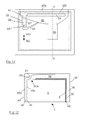
- Fig. 7 shows a plan view of the housing 1 corresponding to the sectional area III-III of Fig. 6 (ie without upper housing wall) a more detailed, not true to scale view of the housing interior with various elements arranged therein. From this point of view, the spaces 36 between the housing body 34 and housing cover 35 are clearly visible, namely the lateral spaces 44, the front gap 45 and the rear gap 46. Because of the three viewing windows 41, 42, 43, the front gap 45 is perpendicular to a first front intermediate space 45a between the middle viewing window 42 and outer viewing window 43 and a second front gap 45b between the middle viewing window 42 and inner viewing window 41 divided. Of course The spaces must not be empty, but may have different elements therein, such as. As lifting elements 10, brackets, bushings, insulation, air guide elements such as baffles, screws, struts, etc., and not every space 36 must allow a significant flow of air.
- electrical or electronic assemblies 47 such as the control circuit 13, a drive device 48 and a ventilation device 49th
- the ventilation device 49 comprises at least one fan, which in this embodiment is exactly one fan which draws in air from two directions by means of two suction openings.
- a two-part fan is advantageously used, in which in addition the exhaust air is output at least substantially unmixed.
- the double-radial fan 50 shown here which has two opposite suction openings and laterally discharges sucked-in air. In this case, the two sucked air flows are discharged substantially laterally parallel to each other.
- an intake opening of the double-radial fan 50 is connected to an intake channel 51 which at least partially covers the front intermediate space 45 and thereby draws cooling air from below from the lower ventilation openings 37 through the front intermediate space 45 during operation.
- the front gap 45 is cooled for improved user safety, which provides a rather low thermal insulation because of the viewing window 4, 41-43.
- the other (rear) suction port of the double-radial fan 50 is open.
- cooling air is sucked in particular from the lateral interspaces 44 and the rear gap 46 and flows over the upper surface 38 to the fan 50.
- the components arranged on the upper surface 38 are also circulated or flowed through and thus cooled. This is particularly advantageous for the electronic modules 47
- the exhaust air of the fan 50 passes through an exhaust duct 52 to an overhead air outlet 53 which blows out the air through the vent opening (s) 39 of FIG.
- the drive device 48 comprises a motor 9, which is fastened centrally on the surface 38 of the housing body 34 and on which a guide housing 54 rests. Through the guide housing 54 run two guide channels (not shown).
- the guide housing 54 has a circular recess for insertion of a pinion 55 of the motor 9.
- the guide channels lead open laterally past the recess, so that located in the guide channels ropes, cables, etc. are brought into engagement with the pinion 55.
- guide tubes 56 are mounted, which together with the guide channels form continuous cable channels.
- the guide tubes 56 extend in this embodiment from the guide housing 54 to the edge of the upper surface 38 in an area above the lifting elements 10 and further beyond the edge down into the lifting elements 10 into it.
- each of the two cable channels runs a pitch cable as a drive cable (not shown).
- the pitch cable has a bendable metal core and is wrapped in wire.
- One end of each pitch cable is firmly connected to the bottom door 7, the other is free. Since both pitch cables are on opposite sides in engagement with the pinion 55, they are linearly displaced by rotation of the pinion 55 in opposite directions.
- the ascending cable drive can be obtained, for example, from WEBASTO, Germany.
- the guide tubes 56 are elastically deformable, z. B. molded from aluminum injection.
- At least one load-carrying guide tube 56 ie, a guide tube 56 which guides a portion of a pitch cable which is fixedly connected to the floor door 7 directly or indirectly, thereby bearing a load on this portion of the pitch cable
- a support 57 rests on a support 57 .
- the bearing force depends on the size of the load on the pitch cable.
- a support 57 is provided for each load-carrying guide tube 56.
- the pads 57 are located substantially at the edge of the upper surface 38 of the housing body 34 so that the load deflectable length - the "arm" - of the guide tube 56 becomes large.
- the load dependence of the respective guide tube 56 on the support 57 is considered as large as possible.
- the contact force depends, for example, on the loading of the bottom door 7 or placing it on a base or an object. By measuring the contact force, for example, an overload of the bottom door 7 or a pinch protection can be realized.
- the length of the guide tubes 56 is of structural design and may be relatively short or may extend to the attachment of the pitch cable to the bottom door 7 (when closed).
- riser drive is not mandatory, but due to the simple design and installation and the precise displacement advantageous.
- Alternative drives include, for example, those driving a cable drum, etc.
- FIG. 8 shows a simplified diagram analogous to FIG. 6 with air movements indicated schematically by dashed arrows.
- fans 50, intake duct 51 and exhaust duct 52 are shown without cover.
- FIG. 9 schematically shows a variant of the exhaust air duct 52 from FIG. 8 with an inlet air duct 60 and an associated outlet air duct 61 integrally introduced therein.
- the two ducts 60, 61 serve to cool a lamp 63, as is explained in more detail in FIG.
- the intake air passage 60 is a port having an opening inclined toward the fan 50, so that air flowing in the exhaust passage 52 effectively presses into the intake air passage 60.
- the inlet air channel 60 leads at the other end into a lamp (see also Fig. 10), the lamp (s) are cooled by the air flow.
- the outlet air duct 61 allows the air to escape from the luminaire back into the exhaust duct 52.
- the flow divider 58 together with the use of a double-radial fan 50, ensures that substantially only the air sucked in through the lateral spaces 45 and / or the rear gap 46 reaches the light 62 via the air channels 60, 61; since the air drawn in from the front intermediate space 45 is mixed with air from the cooking chamber 3 at-typically-the open vapor flap 59 and this air is comparatively contaminated. z. B. by Gardämpfe.
- Fig. 10 shows a sectional side view along the section line IV-IV of Fig. 9, the arrangement of inlet air duct 60 and outlet air duct 61, as a nozzle through the wall of the housing body 34, filled with insulating space 40 (dashed lines) and the wall the muffle 5 are led to the lamp 62.
- the intake air passage 60 is provided with a wind catcher at its end extending into the exhaust passage to effectively direct the flowing air into the light 62.
- the luminaire 62 here is a ceiling lamp (see also FIG. 3) with a lamp 63 in the form of a mains voltage incandescent lamp, which is surrounded by a lamp housing 64. As indicated here by the dashed arrows, the - comparatively cool - air sweeps past the lamp 63 and thereby cools it, as well as by entrainment of the - comparatively warm - air in the lamp housing 64.
- Fig. 11 shows another embodiment of a ventilation device 49, in which now the intake passage 51, the vapor flap 59, an actuator holder 65 and a pivotable, resilient actuating lever 66 are made in one piece.
- the operating lever 66 is connected via an integrated connecting element 67 with the vapor flap 59 for opening and closing the same.
- a dotted inscribed actuator 68 can be used, which rests by a plunger 69 on the lever 66.
- the actuator 68 in the idle or open state, which is present in most operating modes, the actuator 68 is contracted and thus moved in the direction of its rest position WO. In this rest position, the lever 66 is in rest position, and the Wrasenklappe 59 is open. The vapor flap 59 has a spring to keep it open at rest.
- the actuator 68 In the actuated or closed state, the actuator 68 is actuated and expands in the direction of WZ. As a result, the plunger 69 is moved in the same direction WZ and deflects the lever 67 from its rest position. As a result, the lever 67 pulls the vapor flap 59 via the connecting element 67.
- This closed state is activated in particular in a pyrolytic self-cleaning, in which high temperatures in the cooking chamber 3 are required.
- the actuator 68 may be, for example, a Wachsaktuator, which when activated, z. B. on the control board after selecting an operating mode, expands by a heat development and contracts again without activation by cooling. Other types of actuators are possible.
- Fig. 12 shows - not to scale - the housing 1 of Fig. 11 in cross section along the section line VV of Fig. 11 in the open state.
- the opening of the intake channel 51 covers the first and the second front gap 45a, 45b, as well as the vapor flap 59 and the vapor outlet 59a.
- the vapor flap 59 opens in the direction of the fan 50 and is shown open. In the open state, air is thus sucked from the cooking chamber 3 through the Wrasenauslass 59a and, as described above, passed to the outside. It can be seen that the opened vapor flap 59 reduces the flow cross-section to the associated opening of the fan 50 in comparison to a closed position.
- the open vapor flap 59 defines the smallest flow cross-section in the intake channel 51 and thus acts as an air flow regulator.
- the Wrasenklappe 59 firstly as a closure element of the Wrasenö réelle and secondly as a flow regulator is the ventilation adjustable in the front part particularly advantageous. Because in the open state, when the temperature in the cooking chamber 3 is not set so high (typically ⁇ 250 ° C), the air flow through the front gap 45 is not maximum because of the smaller flow cross-section, and need not be.
- the temperature in the cooking chamber 3 can become very high (typically> 400 ° C), and the flow cross-section in the intake passage 51 is greater, so that the ventilation performance through the front gap 45 is higher, causing the View window 4 can be cooled more.
Landscapes
- Engineering & Computer Science (AREA)
- Chemical & Material Sciences (AREA)
- Combustion & Propulsion (AREA)
- Mechanical Engineering (AREA)
- General Engineering & Computer Science (AREA)
- Electric Stoves And Ranges (AREA)
Applications Claiming Priority (1)
| Application Number | Priority Date | Filing Date | Title |
|---|---|---|---|
| DE200510044701 DE102005044701A1 (de) | 2005-09-19 | 2005-09-19 | Hocheinbau-Gargerät |
Publications (1)
| Publication Number | Publication Date |
|---|---|
| EP1767863A2 true EP1767863A2 (fr) | 2007-03-28 |
Family
ID=37734006
Family Applications (1)
| Application Number | Title | Priority Date | Filing Date |
|---|---|---|---|
| EP20060120425 Withdrawn EP1767863A2 (fr) | 2005-09-19 | 2006-09-11 | Appareil de cuisson à encastrer en hauteur |
Country Status (2)
| Country | Link |
|---|---|
| EP (1) | EP1767863A2 (fr) |
| DE (1) | DE102005044701A1 (fr) |
Families Citing this family (1)
| Publication number | Priority date | Publication date | Assignee | Title |
|---|---|---|---|---|
| ITTO20080292A1 (it) * | 2008-04-15 | 2009-10-16 | Indesit Co Spa | Apparato di cottura domestico comprendente un'unita' pensile |
Family Cites Families (3)
| Publication number | Priority date | Publication date | Assignee | Title |
|---|---|---|---|---|
| DE29821158U1 (de) * | 1998-11-26 | 2000-03-30 | AEG Hausgeräte GmbH, 90429 Nürnberg | Garofen mit Kühlung und Wrasenabführung |
| DE10307086A1 (de) * | 2003-02-19 | 2004-09-09 | Electrolux Home Products Corporation N.V. | Garofen |
| FR2876781B1 (fr) * | 2004-10-18 | 2007-01-26 | Brandt Ind Sas | Four de cuisson comportant un dispositif de ventilation des organes de commande |
-
2005
- 2005-09-19 DE DE200510044701 patent/DE102005044701A1/de not_active Withdrawn
-
2006
- 2006-09-11 EP EP20060120425 patent/EP1767863A2/fr not_active Withdrawn
Also Published As
| Publication number | Publication date |
|---|---|
| DE102005044701A1 (de) | 2007-03-22 |
Similar Documents
| Publication | Publication Date | Title |
|---|---|---|
| DE102005044626A1 (de) | Gargerät | |
| DE3346019C2 (de) | Backofen | |
| EP1767863A2 (fr) | Appareil de cuisson à encastrer en hauteur | |
| DE102005044691A1 (de) | Hocheinbau-Gargerät | |
| WO2007033927A1 (fr) | Appareil de cuisson | |
| WO2007033935A1 (fr) | Appareil de cuisson monte en hauteur | |
| EP1929212A1 (fr) | Appareil de cuisson | |
| DE102005044646B4 (de) | Gargerät | |
| WO2007033919A1 (fr) | Appareil de cuisson | |
| EP1917480B1 (fr) | Appareil de cuisson | |
| WO2007088082A2 (fr) | Appareil de cuisson | |
| DE102005044690A1 (de) | Hocheinbau-Gargerät | |
| WO2007088083A1 (fr) | Appareil à pyrolyse | |
| EP1931919A1 (fr) | Appareil de cuisson monte en hauteur | |
| EP1982114B1 (fr) | Appareil de cuisson | |
| DE102010042788A1 (de) | Gargerät mit einem Backofen | |
| EP1929209A1 (fr) | Appareil de cuisson monte en hauteur | |
| DE102005044625A1 (de) | Gargerät | |
| EP1929214A1 (fr) | Appareil de cuisson monte en hauteur | |
| EP1917478B1 (fr) | Appareil de cuisson | |
| EP1767866A2 (fr) | Appareil de cuisson | |
| WO2007020165A1 (fr) | Appareil de cuisson | |
| WO2007033920A1 (fr) | Appareil de cuisson | |
| EP1754939A2 (fr) | Appareil de cuisson mural | |
| EP1982115A1 (fr) | Appareil de cuisson |
Legal Events
| Date | Code | Title | Description |
|---|---|---|---|
| PUAI | Public reference made under article 153(3) epc to a published international application that has entered the european phase |
Free format text: ORIGINAL CODE: 0009012 |
|
| AK | Designated contracting states |
Kind code of ref document: A2 Designated state(s): AT BE BG CH CY CZ DE DK EE ES FI FR GB GR HU IE IS IT LI LT LU LV MC NL PL PT RO SE SI SK TR |
|
| AX | Request for extension of the european patent |
Extension state: AL BA HR MK YU |
|
| STAA | Information on the status of an ep patent application or granted ep patent |
Free format text: STATUS: THE APPLICATION IS DEEMED TO BE WITHDRAWN |
|
| 18D | Application deemed to be withdrawn |
Effective date: 20110401 |