EP1767882B1 - Solarabsorber - Google Patents
Solarabsorber Download PDFInfo
- Publication number
- EP1767882B1 EP1767882B1 EP06019514.6A EP06019514A EP1767882B1 EP 1767882 B1 EP1767882 B1 EP 1767882B1 EP 06019514 A EP06019514 A EP 06019514A EP 1767882 B1 EP1767882 B1 EP 1767882B1
- Authority
- EP
- European Patent Office
- Prior art keywords
- solar
- solar absorber
- absorber
- medium
- phase transition
- Prior art date
- Legal status (The legal status is an assumption and is not a legal conclusion. Google has not performed a legal analysis and makes no representation as to the accuracy of the status listed.)
- Not-in-force
Links
- 239000006096 absorbing agent Substances 0.000 title claims description 42
- 239000012188 paraffin wax Substances 0.000 claims description 18
- 230000007704 transition Effects 0.000 claims description 7
- OKTJSMMVPCPJKN-UHFFFAOYSA-N Carbon Chemical compound [C] OKTJSMMVPCPJKN-UHFFFAOYSA-N 0.000 claims description 6
- 229910002804 graphite Inorganic materials 0.000 claims description 6
- 239000010439 graphite Substances 0.000 claims description 6
- 239000011159 matrix material Substances 0.000 claims description 4
- 239000012530 fluid Substances 0.000 claims description 3
- 238000000034 method Methods 0.000 claims description 3
- XLYOFNOQVPJJNP-UHFFFAOYSA-N water Substances O XLYOFNOQVPJJNP-UHFFFAOYSA-N 0.000 description 17
- 239000012267 brine Substances 0.000 description 5
- 239000011521 glass Substances 0.000 description 5
- 238000002844 melting Methods 0.000 description 5
- 230000008018 melting Effects 0.000 description 5
- HPALAKNZSZLMCH-UHFFFAOYSA-M sodium;chloride;hydrate Chemical compound O.[Na+].[Cl-] HPALAKNZSZLMCH-UHFFFAOYSA-M 0.000 description 5
- YIXJRHPUWRPCBB-UHFFFAOYSA-N magnesium nitrate Chemical compound [Mg+2].[O-][N+]([O-])=O.[O-][N+]([O-])=O YIXJRHPUWRPCBB-UHFFFAOYSA-N 0.000 description 4
- 230000005855 radiation Effects 0.000 description 3
- 229910013553 LiNO Inorganic materials 0.000 description 2
- 229910019427 Mg(NO3)2-6H2O Inorganic materials 0.000 description 2
- 229910052784 alkaline earth metal Inorganic materials 0.000 description 2
- 238000002425 crystallisation Methods 0.000 description 2
- 230000008025 crystallization Effects 0.000 description 2
- 238000004146 energy storage Methods 0.000 description 2
- 230000004927 fusion Effects 0.000 description 2
- 238000010438 heat treatment Methods 0.000 description 2
- IIPYXGDZVMZOAP-UHFFFAOYSA-N lithium nitrate Chemical compound [Li+].[O-][N+]([O-])=O IIPYXGDZVMZOAP-UHFFFAOYSA-N 0.000 description 2
- 239000000203 mixture Substances 0.000 description 2
- 238000005192 partition Methods 0.000 description 2
- 239000011833 salt mixture Substances 0.000 description 2
- 239000011232 storage material Substances 0.000 description 2
- RYGMFSIKBFXOCR-UHFFFAOYSA-N Copper Chemical group [Cu] RYGMFSIKBFXOCR-UHFFFAOYSA-N 0.000 description 1
- 241000589248 Legionella Species 0.000 description 1
- 208000007764 Legionnaires' Disease Diseases 0.000 description 1
- 230000001154 acute effect Effects 0.000 description 1
- 239000003513 alkali Substances 0.000 description 1
- 150000001342 alkaline earth metals Chemical class 0.000 description 1
- 229910052802 copper Inorganic materials 0.000 description 1
- 239000010949 copper Substances 0.000 description 1
- 238000005338 heat storage Methods 0.000 description 1
- 238000009413 insulation Methods 0.000 description 1
- 239000007788 liquid Substances 0.000 description 1
- 239000000463 material Substances 0.000 description 1
- 150000002823 nitrates Chemical class 0.000 description 1
- 231100000252 nontoxic Toxicity 0.000 description 1
- 230000003000 nontoxic effect Effects 0.000 description 1
- 230000009965 odorless effect Effects 0.000 description 1
- 239000003208 petroleum Substances 0.000 description 1
- 238000007670 refining Methods 0.000 description 1
- 230000000630 rising effect Effects 0.000 description 1
- 229930195734 saturated hydrocarbon Natural products 0.000 description 1
- 239000007787 solid Substances 0.000 description 1
- 239000000126 substance Substances 0.000 description 1
- 230000009967 tasteless effect Effects 0.000 description 1
- 238000003809 water extraction Methods 0.000 description 1
- 239000001993 wax Substances 0.000 description 1
Images


Classifications
-
- F—MECHANICAL ENGINEERING; LIGHTING; HEATING; WEAPONS; BLASTING
- F28—HEAT EXCHANGE IN GENERAL
- F28D—HEAT-EXCHANGE APPARATUS, NOT PROVIDED FOR IN ANOTHER SUBCLASS, IN WHICH THE HEAT-EXCHANGE MEDIA DO NOT COME INTO DIRECT CONTACT
- F28D20/00—Heat storage plants or apparatus in general; Regenerative heat-exchange apparatus not covered by groups F28D17/00 or F28D19/00
- F28D20/02—Heat storage plants or apparatus in general; Regenerative heat-exchange apparatus not covered by groups F28D17/00 or F28D19/00 using latent heat
- F28D20/023—Heat storage plants or apparatus in general; Regenerative heat-exchange apparatus not covered by groups F28D17/00 or F28D19/00 using latent heat the latent heat storage material being enclosed in granular particles or dispersed in a porous, fibrous or cellular structure
-
- F—MECHANICAL ENGINEERING; LIGHTING; HEATING; WEAPONS; BLASTING
- F24—HEATING; RANGES; VENTILATING
- F24S—SOLAR HEAT COLLECTORS; SOLAR HEAT SYSTEMS
- F24S60/00—Arrangements for storing heat collected by solar heat collectors
- F24S60/10—Arrangements for storing heat collected by solar heat collectors using latent heat
-
- F—MECHANICAL ENGINEERING; LIGHTING; HEATING; WEAPONS; BLASTING
- F24—HEATING; RANGES; VENTILATING
- F24S—SOLAR HEAT COLLECTORS; SOLAR HEAT SYSTEMS
- F24S60/00—Arrangements for storing heat collected by solar heat collectors
- F24S60/30—Arrangements for storing heat collected by solar heat collectors storing heat in liquids
-
- F—MECHANICAL ENGINEERING; LIGHTING; HEATING; WEAPONS; BLASTING
- F24—HEATING; RANGES; VENTILATING
- F24S—SOLAR HEAT COLLECTORS; SOLAR HEAT SYSTEMS
- F24S70/00—Details of absorbing elements
- F24S70/60—Details of absorbing elements characterised by the structure or construction
-
- F—MECHANICAL ENGINEERING; LIGHTING; HEATING; WEAPONS; BLASTING
- F28—HEAT EXCHANGE IN GENERAL
- F28D—HEAT-EXCHANGE APPARATUS, NOT PROVIDED FOR IN ANOTHER SUBCLASS, IN WHICH THE HEAT-EXCHANGE MEDIA DO NOT COME INTO DIRECT CONTACT
- F28D20/00—Heat storage plants or apparatus in general; Regenerative heat-exchange apparatus not covered by groups F28D17/00 or F28D19/00
- F28D20/02—Heat storage plants or apparatus in general; Regenerative heat-exchange apparatus not covered by groups F28D17/00 or F28D19/00 using latent heat
-
- F—MECHANICAL ENGINEERING; LIGHTING; HEATING; WEAPONS; BLASTING
- F24—HEATING; RANGES; VENTILATING
- F24S—SOLAR HEAT COLLECTORS; SOLAR HEAT SYSTEMS
- F24S10/00—Solar heat collectors using working fluids
- F24S10/70—Solar heat collectors using working fluids the working fluids being conveyed through tubular absorbing conduits
- F24S10/74—Solar heat collectors using working fluids the working fluids being conveyed through tubular absorbing conduits the tubular conduits are not fixed to heat absorbing plates and are not touching each other
- F24S10/748—Solar heat collectors using working fluids the working fluids being conveyed through tubular absorbing conduits the tubular conduits are not fixed to heat absorbing plates and are not touching each other the conduits being otherwise bent, e.g. zig-zag
-
- F—MECHANICAL ENGINEERING; LIGHTING; HEATING; WEAPONS; BLASTING
- F24—HEATING; RANGES; VENTILATING
- F24S—SOLAR HEAT COLLECTORS; SOLAR HEAT SYSTEMS
- F24S80/00—Details, accessories or component parts of solar heat collectors not provided for in groups F24S10/00-F24S70/00
- F24S80/50—Elements for transmitting incoming solar rays and preventing outgoing heat radiation; Transparent coverings
- F24S80/56—Elements for transmitting incoming solar rays and preventing outgoing heat radiation; Transparent coverings characterised by means for preventing heat loss
-
- Y—GENERAL TAGGING OF NEW TECHNOLOGICAL DEVELOPMENTS; GENERAL TAGGING OF CROSS-SECTIONAL TECHNOLOGIES SPANNING OVER SEVERAL SECTIONS OF THE IPC; TECHNICAL SUBJECTS COVERED BY FORMER USPC CROSS-REFERENCE ART COLLECTIONS [XRACs] AND DIGESTS
- Y02—TECHNOLOGIES OR APPLICATIONS FOR MITIGATION OR ADAPTATION AGAINST CLIMATE CHANGE
- Y02E—REDUCTION OF GREENHOUSE GAS [GHG] EMISSIONS, RELATED TO ENERGY GENERATION, TRANSMISSION OR DISTRIBUTION
- Y02E10/00—Energy generation through renewable energy sources
- Y02E10/40—Solar thermal energy, e.g. solar towers
-
- Y—GENERAL TAGGING OF NEW TECHNOLOGICAL DEVELOPMENTS; GENERAL TAGGING OF CROSS-SECTIONAL TECHNOLOGIES SPANNING OVER SEVERAL SECTIONS OF THE IPC; TECHNICAL SUBJECTS COVERED BY FORMER USPC CROSS-REFERENCE ART COLLECTIONS [XRACs] AND DIGESTS
- Y02—TECHNOLOGIES OR APPLICATIONS FOR MITIGATION OR ADAPTATION AGAINST CLIMATE CHANGE
- Y02E—REDUCTION OF GREENHOUSE GAS [GHG] EMISSIONS, RELATED TO ENERGY GENERATION, TRANSMISSION OR DISTRIBUTION
- Y02E60/00—Enabling technologies; Technologies with a potential or indirect contribution to GHG emissions mitigation
- Y02E60/14—Thermal energy storage
-
- Y—GENERAL TAGGING OF NEW TECHNOLOGICAL DEVELOPMENTS; GENERAL TAGGING OF CROSS-SECTIONAL TECHNOLOGIES SPANNING OVER SEVERAL SECTIONS OF THE IPC; TECHNICAL SUBJECTS COVERED BY FORMER USPC CROSS-REFERENCE ART COLLECTIONS [XRACs] AND DIGESTS
- Y02—TECHNOLOGIES OR APPLICATIONS FOR MITIGATION OR ADAPTATION AGAINST CLIMATE CHANGE
- Y02E—REDUCTION OF GREENHOUSE GAS [GHG] EMISSIONS, RELATED TO ENERGY GENERATION, TRANSMISSION OR DISTRIBUTION
- Y02E70/00—Other energy conversion or management systems reducing GHG emissions
- Y02E70/30—Systems combining energy storage with energy generation of non-fossil origin
Definitions
- the invention relates to a solar absorber with a housing and fluid-carrying lines, wherein within the housing, the fluid-carrying lines are guided in a phase change heat storing medium.
- Solar absorbers are known from the prior art, in which a fluid is heated to then thermally load a hot water tank. Very often find very voluminous hot water storage use. It is also known that below 55 ° C in hot water tanks the risk of Legione Ilen Struktur exists. As a result, solar storage are preheated mostly only with solar energy and heated at least at certain intervals by a further heat source above 55 ° C, on the one hand die off the Legionella and on the other hand see a corresponding hot water comfort available.
- GB 387 828 shows a solar absorber whose surface corresponds to the negative of truncated truncated cones.
- WO 01/53756 A2 is a solar absorber with latent storage material known.
- the latent storage material is hereby housed in plates, which have a recess on both sides; This also increases the absorbing surface.
- Object of the present invention is to increase the heat capacity of the actual solar absorber and / or solar storage and thus to reduce the necessary storage volume.
- the phase-change heat-storing medium is paraffin, and in the phase change is thus a transition from liquid to solid.
- Paraffin (C n H 2n + 2 ) is a collective term for saturated hydrocarbon mixtures derived primarily from petroleum. Paraffins, also referred to as waxes, are organic substances which, after refining, are odorless, tasteless and non-toxic. It is distinguished between normal paraffins and isoparaffins. Normal paraffins are simple, elongated chains. Isoparaffins have branching branches from a long basic chain. For thermal engineering applications are mostly normal paraffins used. The melting temperature of the paraffins is between 30 and 90 ° C with a number n between 18 and 50. With increasing molecular chain length or increasing molecular weight, the melting temperature of the material increases steadily. Paraffins are well suited for thermal applications.
- paraffins lies in the use of latent heat during the phase change. A minor part is stored as sensible heat.
- the spec. Heat capacity of heat paraffin is about 2.1 kJ / (kg • K), the enthalpy of fusion at 180 to 230 kJ / kg.
- paraffins are ideally suited for heat storage. Paraffin stores many times the heat of water.
- the paraffin is housed in a porous graphite matrix, the graphite thus receives on the one hand paraffin, and on the other hand serves to absorb infrared heat well.
- FIG. 1 shows a solar absorber with a housing 12 and a glass plate 3, through which infrared solar radiation 5 can get into the absorber.
- a thermal insulation 11 Within the frame 12 there is a thermal insulation 11.
- a paraffin container 10 consisting of a porous graphite matrix 8, in which paraffin 9 is located.
- paraffin 9 is located in the middle of the porous graphite matrix 8 .
- copper lines 4 in which brine flows.
- FIG. 2 shows a solar absorber 1, which is connected via a feed line 17 and return line 18 in which a pump 15 is connected to a solar storage tank 13.
- the feed line 17 leads to a heat exchanger 14, in which the brine heated by the solar absorber 1 is cooled and gives off heat to the solar accumulator 13.
- the brine is conveyed by the circulation pump 15.
- a hot water extraction line 19 hot water can be removed from the store.
- the solar tank 13 water is supplied again. Not shown are the hot water consumers and the conventional device for storage water heating.
- the solar absorber 1 In sunshine, the solar absorber 1 is heated, and as soon as the solar absorber 1 reaches a temperature which is greater than the solar storage temperature, the circulation pump 15 starts to run and thus to charge the hot water storage tank 13. Once the hot water tank 13 is loaded, z. B. when it has reached a temperature of 60 ° C, the circulation pump 15 is turned off. Since the sun still heats the solar absorber 1 in this case, the paraffin 9 in the solar absorber 1 starts to melt and thus absorb crystallization energy. The energy of the phase transition is now in Paraffin 9 saved. With a conventional solar absorber, this energy would be lost. When cloudy or sunset, the temperature in the solar absorber 1 is still above the temperature of the phase change, z. B. above 65 ° C. When the paraffin cools, it crystallizes and the crystallization energy is released. This is discharged via the graphite to the soleshareden line 17 to the hot water tank 13.
- the storage volume can be reduced by 30% to 50%.
- other media would also be suitable for absorbing the phase-change energy, in particular salt mixtures.
- mixtures of magnesium nitrate with nitrates or alkali or alkaline earth metals can be used.
- salt mixtures based on magnesium nitrate and lithium nitrate (Mg (NO 3 ) 2 6 H 2 O and LiNO 3 , eg 87-92% Mg (NO 3 ) 2 6 H 2 O and 8-13% LiNO 3 melting temperature 70 ° C. +/- 2 K, heat of fusion 54.32 Wh / kg) is suitable for this purpose.
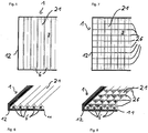
- FIG. 3 shows a solar absorber 1 according to the invention as a further development of the solar absorber generally shown FIG. 1 in which the surface 21 of the phase-change heat-storing medium has a conical surface 21 on the side of the glass plate 3.
- the air circulation is hindered in the solar absorber 1; by this heat can be dissipated from the surface 21 to the glass plate 3 and from this into the environment.
- the conical surface 21 leads in an advantageous embodiment almost to contact the glass plate 3, so that almost no convection can get over the tips.
- FIG. 3 According to the profile is according to FIG. 3 into the depth continuously. This is in FIG. 5 with view perpendicular to the glass plate 3 and in FIG. 6 shown in perspective. According to the invention - as in the FIGS. 7 and 8 shown - to separate such a profile in the valleys by parallel partitions 26, so that in the valleys a convective flow is avoided.
- FIG. 4 shows a solar absorber 1 with a solar storage tank 13 connected thereto, in which a paraffin container 10 is arranged in the interior of the solar accumulator 13. Paraffin has a higher heat capacity than water, which is why with the same size more heat in a solar storage tank 13 according to FIG. 4 can be stored as in a conventional water storage.
- a switching valve 25 from which a line 23 goes to a secondary heat exchanger 22.
- the secondary heat exchanger 22 is - not shown - connected to a heating and / or domestic water circuit. From the secondary heat exchanger 22, a line 24 leads to the flow line 17th
- the circulation pump 15 promotes brine between the solar absorber 1 and the solar storage tank 13.
- the solar storage tank 13 with the paraffin container 10 contained therein is heated and heat is stored therein. If the melting temperature is exceeded, the paraffin container 10 absorbs heat without the temperature in the solar accumulator 13 rising.
- the changeover valve 25 switches, whereby the circulation pump 15 promotes brine between the solar storage tank 13 and the secondary heat exchanger 22. Will the Farther below the melting temperature, the paraffin container 10 releases heat without the temperature falling in the solar accumulator 13.
Landscapes
- Engineering & Computer Science (AREA)
- Thermal Sciences (AREA)
- General Engineering & Computer Science (AREA)
- Mechanical Engineering (AREA)
- Physics & Mathematics (AREA)
- Chemical & Material Sciences (AREA)
- Sustainable Energy (AREA)
- Combustion & Propulsion (AREA)
- Sustainable Development (AREA)
- Life Sciences & Earth Sciences (AREA)
- Dispersion Chemistry (AREA)
- Heat-Pump Type And Storage Water Heaters (AREA)
- Road Paving Structures (AREA)
Description
- Die Erfindung bezieht sich auf einen Solarabsorber mit einem Gehäuse und fluidführenden Leitungen, wobei innerhalb des Gehäuses die fluidführende Leitungen in einem Phasenumwandlungswärme speicherndem Medium geführt werden.
- Aus dem Stand der Technik sind Solarabsorber bekannt, in welchen ein Fluid erhitzt wird, um sodann einen Warmwasserspeicher thermisch zu beladen. Sehr häufig finden sehr voluminöse Warmwasserspeicher Verwendung. Ferner ist bekannt, dass unterhalb von 55° C in Warmwasserspeichern die Gefahr der Legione Ilenbildung besteht. Als Folge dessen werden Solarspeicher meistens nur mit solarer Energie vorgeheizt und zumindest in bestimmten Abständen durch eine weitere Wärmequelle über 55° C erhitzt, damit einerseits die Legionellen absterben und andererseits ein entsprechender Warmwasserkomfort zur Verfügung seht.
- Aus der
WO 85/00212 A FR 2 503 855 A DE 39 10 356 A sind Solarabsorber mit Phasenumwandlungsenergie speichernden Medien bekannt. AusUS 4 111 189 ,EP 95 187 A DE 100 43 533 A undDE 198 15 521 A sind Solarsysteme mit Phasenumwandlungsenergie speichernden Medien in einem Solarspeicher bekannt.DE 27 54 873 A offenbart einen Solarabsorber mit Rippen, welche Wellen- oder Zick-Zack-Form haben können. Die Spitzen der Wellen oder Rippen haben Kontakt zur Scheibe des Kollektors. -
GB 387 828 - Aus
WO 01/53756 A2 - Aufgabe der vorliegenden Erfindung ist es, die Wärmekapazität des eigentlichen Solarabsorbers und / oder des Solarspeichers zu erhöhen und somit das notwendige Speichervolumen zu reduzieren.
- Bei dem erfindungsgemäßen Solarabsorber gemäß Anspruch 1 weist die Oberfläche des Mediums auf der der Sonneneinstrahlung zugewandten Seite eine nichtebene Struktur mit kegelförmigem Querschnitt mit vorzugsweise spitzen Winkeln auf, wobei die Struktur eine kontinuierliche Erstreckung senkrecht zu diesem Querschnitt, aufweist, wobei das Profil der kegelförmigen Oberfläche durch Trennwände, welche senkrecht zu der kontinuierlichen Erstreckung der Struktur verlaufen, unterbrochen ist. Es ergibt sich der Vorteil, dass reflektierte Sonnenstrahlen nicht wieder in die Umgebung reflektiert werden, sondern im Solarabsorber verbleiben. Es ergibt sich weiter der Vorteil, dass konvektiver Wärmeaustausch durch Behinderung einer Strömung vermieden werden kann.
- Gemäß den Merkmalen des Anspruchs 2 handelt es sich bei dem Phasenumwandlungswärme speicherndem Medium um Paraffin, und bei dem Phasenwechsel somit um einen Übergang von flüssig zu fest.
- Paraffin (CnH2n+2) stellt eine Sammelbezeichnung für gesättigte Kohlenwasserstoffgemische dar, die hauptsächlich aus Erdöl gewonnen werden. Paraffine, die auch als Wachse bezeichnet werden, sind organische Stoffe, die nach der Raffination geruchlos, geschmacklos und ungiftig sind. Es wird zwischen Normalparaffine und Isoparaffine unterschieden. Normalparaffine sind einfache, lang gestreckte Ketten. Isoparaffine haben von einer langen Grundkette verzweigende Äste. Für wärmetechnische Anwendungen kommen überwiegend Normalparaffine zum Einsatz. Die Schmelztemperatur der Paraffine liegt zwischen 30 bis 90°C bei einer Zahl n zwischen 18 und 50. Mit steigender Molekülkettenlänge bzw. steigender Molmasse nimmt die Schmelztemperatur des Materials stetig zu. Paraffine sind gut für thermische Anwendungen geeignet. Der Vorteil der Paraffine liegt in der Nutzung der latenten Wärme während des Phasenwechsels. Ein geringerer Teil wird als sensible Wärme gespeichert. Die spez. Wärmekapazität von Wärmeparaffin liegt bei etwa 2,1 kJ/(kg•K), die Schmelzenthalpie bei 180 bis 230 kJ/kg. Hierdurch sind Paraffine bestens zur Wärmespeicherung geeignet. Paraffin speichert ein Vielfaches der Wärme von Wasser.
- Gemäß den Merkmalen des Anspruchs 3 ist das Paraffin in einer porösen Graphitmatrix untergebracht, das Graphit nimmt somit einerseits Paraffin auf, und dient andererseits dazu, Infrarotwärme gut zu absorbieren.
- Die Verfahrensansprüche schützen eine besonders vorteilhafte Betriebsweise der Solarabsorber gemäß den Ansprüchen 1 bis 3.
- Die Erfindung wird nun anhand der Zeichnungen detailliert erläutert.
-
Figur 1 zeigt einen Solarabsorber, -
Figur 2 einen Solarabsorber mit einem Warmwasserspeicher, -
Figur 3 einen erfindungsgemäßen Solarabsorber -
Figur 4 einen Solarabsorber mit Phasenumwandlungswärme speicherndem Medium in einem Warmwasserspeicher, -
Figur 5 und 6 einen Solarabsorber sowieFiguren 7 und 8 den erfindungsgemäßen Solarabsorber im Detail. -
Figur 1 zeigt einen Solarabsorber mit einem Gehäuse 12 und einer Glasplatte 3, durch welche infrarote Sonnenstrahlung 5 in den Absorber gelangen kann. Innerhalb des Rahmens 12 befindet sich eine Wärmedämmung 11. Hierin wiederum befindet sich ein Paraffinbehälter 10, bestehend aus einer porösen Graphitmatrix 8, in welcher sich Paraffin 9 befindet. Inmitten der porösen Graphitmatrix 8 sind fluidführende Leitungen 6 untergebracht. Im konkreten Fall handelt es sich um Kupferleitungen 4, in welchen Sole strömt. -
Figur 2 zeigt einen Solarabsorber 1, welcher über eine Vorlaufleitung 17 und Rücklaufleitung 18, in der sich eine Pumpe 15 befindet, mit einem Solarspeicher 13 verbunden ist. Die Vorlaufleitung 17 führt zu einem Wärmetauscher 14, in dem die vom Solarabsorber 1 erwärmte Sole abgekühlt wird und Wärme auf den Solarspeicher 13 abgibt. Die Sole wird von der Umwälzpumpe 15 gefördert. Zum Ausgleich temperaturbedingter Volumenschwankungen befindet sich ein Ausdehnungsgefäß 16 in der Rücklaufleitung 18. Über eine Warmwasserentnahmeleitung 19 kann warmes Wasser aus dem Speicher entnommen werden. Über die Zuführleitung 20 wird dem Solarspeicher 13 Wasser wieder zugeführt. Nicht dargestellt sind die Brauchwasserverbraucher und die konventionelle Vorrichtung zur Speicherwassererhitzung. - Bei Sonnenschein wird der Solarabsorber 1 erhitzt, und sobald der Solarabsorber 1 eine Temperatur erreicht, die größer als die Solarspeichertemperatur ist, beginnt die Umwälzpumpe 15 zu laufen und somit den Warmwasserspeicher 13 zu laden. Sobald der Warmwasserspeicher 13 geladen ist, z. B. wenn er eine Temperatur von 60° C erreicht hat, wird die Zirkulationspumpe 15 abgeschaltet. Da die Sonne in diesem Fall nach wie vor den Solarabsorber 1 erhitzt, beginnt das Paraffin 9 in dem Solarabsorber 1 zu schmelzen und somit Kristallisationsenergie aufzunehmen. Die Energie des Phasenübergangs ist nun im Paraffin 9 gespeichert. Bei einem konventionellen Solarabsorber wäre diese Energie verloren. Bei Bewölkung oder Sonnenuntergang ist zunächst die Temperatur in dem Solarabsorber 1 noch oberhalb der Temperatur des Phasenwechsels, z. B. oberhalb 65° C. Kühlt sich das Paraffin ab, so kristallisiert es und die Kristallisationsenergie wird frei. Diese wird über das Graphit an die soleführenden Leitung 17 an den Warmwasserspeicher 13 abgegeben.
- Bei einem standardmäßigen Solarabsorber könnte nach dem Sonnenuntergang oder bei Bewölkung keine weitere Energie mehr freigesetzt werden. Mit dem erfindungsgemäßen Solarabsorber kann das Speichervolumen um 30% bis 50% reduziert werden. Neben Paraffin wären auch andere Medien zur Aufnahme der Phasenumwandlungsenergie geeignet, insbesondere Salzgemische. So können beispielsweise Gemische aus Magnesiumnitrat mit Nitraten oder Alkali- oder Erdalkalimetallen verwendet werden. Auch Salzgemische auf der Basis von Magnesiumnitrat und Lithiumnitrat (Mg (NO3)2 6 H2O und LiNO3, z.B. 87-92 % Mg (NO3)2 6 H2O und 8-13 % LiNO3 Schmelztemperatur 70°C +/- 2 K, Schmelzwärme 54,32 Wh/kg) ist hierzu geeignet.
-
Figur 3 zeigt einen erfindungsgemäßen Solarabsorber 1 als Weiterentwicklung des allgemein dargestellten Solarabsorbers ausFigur 1 , bei dem die Oberfläche 21 des Phasenumwandlungswärme speichernde Medium auf der Seite der Glasplatte 3 eine kegelförmige Oberfläche 21 aufweist. Je spitzer die Winkel der Oberfläche 21 sind, desto mehr von der Oberfläche 21 reflektierte Strahlen werden wieder auf die Oberfläche 21 geworfen. Hierdurch wird vermieden, dass reflektierte Strahlung wieder aus dem Solarabsorber 1 gelangt. Andererseits wird die Luftzirkulation im Solarabsorber 1 behindert; durch diese kann Wärme von der Oberfläche 21 zur Glasplatte 3 und von dieser in die Umgebung abgeführt werden. Die kegelförmige Oberfläche 21 führt in einer vorteilhaften Ausgestaltung bis fast zum Kontakt zur Glasplatte 3, so dass nahezu keine Konvektion über die Spitzen geraten kann. - Erfindungsgemäß setzt sich das Profil gemäß
Figur 3 in die Tiefe kontinuierlich fort. Dies ist inFigur 5 mit Blick senkrecht zur Glasplatte 3 und inFigur 6 perspektivisch dargestellt. Erfindungsgemäß ist - wie in denFiguren 7 und 8 dargestellt - ein derartiges Profil in den Tälern durch parallele Trennwände 26 zu trennen, so dass auch in den Tälern eine konvektive Strömung vermieden wird. -
Figur 4 zeigt einen Solarabsorber 1 mit einem daran angeschlossenen Solarspeicher 13, bei dem im Inneren des Solarspeichers 13 ein Paraffinbehälter 10 angeordnet ist. Paraffin hat eine höhere Wärmekapazität als Wasser, weshalb bei gleicher Baugröße mehr Wärme in einem Solarspeicher 13 gemäßFigur 4 gespeichert werden kann als in einem konventionellen Wasserspeicher. - In der Rücklaufleitung 18 befindet sich stromab der Umwälzpumpe 15 ein Umschaltventil 25, von dem eine Leitung 23 zu einem Sekundärwärmeaustauscher 22 abgeht. Der Sekundärwärmeaustauscher 22 ist - nicht dargestellt - mit einem Heiz- und / oder Brauchwasserkreislauf verbunden. Vom Sekundärwärmeaustauscher 22 führt eine Leitung 24 zur Vorlaufleitung 17.
- Beim Ladebetrieb fördert die Umwälzpumpe 15 Sole zwischen Solarabsorber 1 und Solarspeicher 13. Der Solarspeicher 13 mit dem darin enthaltenen Paraffinbehälter 10 wird erhitzt und darin Wärme gespeichert. Wird die Schmelztemperatur überschritten, so nimmt der Paraffinbehälter 10 Wärme auf ohne dass die Temperatur im Solarspeicher 13 steigt. Beim Entladebetrieb schaltet das Umschaltventil 25 um, wodurch die Umwälzpumpe 15 Sole zwischen dem Solarspeicher 13 und dem Sekundärwärmeaustauscher 22 fördert. Wird die Schmelztemperatur unterschritten, so gibt der Paraffinbehälter 10 Wärme ab ohne dass die Temperatur im Solarspeicher 13 fällt.
Claims (5)
- Solarabsorber (1) mit einem Gehäuse (12) und fluidführenden Leitungen (6), innerhalb des Gehäuses (12) die fluidführende Leitungen (6) in einem Phasenumwandlungswärme speicherndem Medium (9) geführt werden, dadurch gekennzeichnet, dass
die Oberfläche (21) des Mediums auf der der Sonneneinstrahlung zugewandten Seite eine nichtebene Struktur mit kegelförmigem Querschnitt mit vorzugsweise spitzen Winkeln aufweist, wobei die Struktur eine kontinuierliche Erstreckung senkrecht zu diesem Querschnitt, aufweist, wobei das Profil der kegelförmigen Oberfläche (21) durch Trennwände (26), welche senkrecht zu der kontinuierlichen Erstreckung der Struktur verlaufen, unterbrochen ist. - Solarabsorber (1) nach Anspruch 1 dadurch gekennzeichnet, dass das Phasenumwandlungswärme speicherndem Medium (9) Paraffin ist.
- Solarabsorber (1) nach Anspruch 1 oder 2, dadurch gekennzeichnet, dass das Phasenumwandlungswärme speichernde Medium in einer porösen Graphitmatrix (8) aufgenommen ist.
- Verfahren zum Betreiben eines Solarabsorber (1) nach einem der Ansprüche 1 bis 3 um thermischen Beladen eines Solarspeichers (13) mit einer Umwälzpumpe (15) zwischen Solarabsorber (1) und Solarspeicher (13), dadurch gekennzeichnet, dass bei geladenem Solarspeicher (13) die Umwälzpumpe (15) abgeschaltet wird, so dass das Phasenumwandlungswärme speicherndem Medium (9) weiter erhitzt wird und Phasenumwandlungsenergie aufnimmt.
- Verfahren zum Betreiben eines Solarabsorbers (1) nach Anspruch 4, dadurch gekennzeichnet, dass die Umwälzpumpe (15) eingeschaltet wird, wenn die Temperatur des Solarspeichers (13) kleiner der Temperatur des Solarabsorbers (1) ist.
Applications Claiming Priority (2)
| Application Number | Priority Date | Filing Date | Title |
|---|---|---|---|
| DE102005046259 | 2005-09-27 | ||
| AT17922005 | 2005-11-02 |
Publications (3)
| Publication Number | Publication Date |
|---|---|
| EP1767882A2 EP1767882A2 (de) | 2007-03-28 |
| EP1767882A3 EP1767882A3 (de) | 2007-10-24 |
| EP1767882B1 true EP1767882B1 (de) | 2018-10-31 |
Family
ID=37532961
Family Applications (1)
| Application Number | Title | Priority Date | Filing Date |
|---|---|---|---|
| EP06019514.6A Not-in-force EP1767882B1 (de) | 2005-09-27 | 2006-09-19 | Solarabsorber |
Country Status (2)
| Country | Link |
|---|---|
| EP (1) | EP1767882B1 (de) |
| DE (1) | DE102006043796A1 (de) |
Families Citing this family (14)
| Publication number | Priority date | Publication date | Assignee | Title |
|---|---|---|---|---|
| FR2918498A1 (fr) * | 2007-07-06 | 2009-01-09 | Antoine Jacques Candeias | Dispositif pour proteger biologiquement contre les rayonnements irradiants, ionisants, neutroniques |
| DE102007047693A1 (de) * | 2007-10-05 | 2009-04-23 | Universität Kassel | Fassaden- oder Dachelement zur Anbringung an einem Gebäude und Verwendung hierfür |
| FR2956727B1 (fr) | 2010-02-23 | 2012-08-24 | Philippe Mulcey | Panneau solaire thermique a rendement eleve |
| US10168105B2 (en) | 2010-05-04 | 2019-01-01 | Basf Se | Device and method for storing heat |
| ES2453094T3 (es) * | 2010-05-04 | 2014-04-04 | Basf Se | Dispositivo y procedimiento para la acumulación de calor |
| DE102010024740B4 (de) * | 2010-06-23 | 2012-04-19 | Robert Bosch Gmbh | Solarabsorber |
| WO2013016744A1 (en) * | 2011-07-28 | 2013-01-31 | Hellman Neil Christopher | Solar water heater with integrated collector and storage |
| SE537409C2 (sv) * | 2012-03-08 | 2015-04-21 | Törnerfälts Fastighets Ab | Tak för upptagande av solenergi |
| AT512838B1 (de) * | 2012-04-02 | 2014-01-15 | Greiner Technology & Innovation Gmbh | Solarspeicherkollektor |
| DE102014100448A1 (de) * | 2014-01-16 | 2015-07-16 | Anton Falkeis | Fassadenelemente mit Latentwärmespeicher |
| CN107044736B (zh) * | 2017-04-25 | 2023-04-07 | 广东五星太阳能股份有限公司 | 一种相变蓄热抗冻型太阳能集热器 |
| CN108163851A (zh) * | 2017-12-25 | 2018-06-15 | 杭州龙灿液态金属科技有限公司 | 一种高频感应加热装置、制备石墨蠕虫的方法以及石墨蠕虫的应用 |
| CN108753264B (zh) * | 2018-07-16 | 2024-04-05 | 东南大学 | 相变储能型太阳能干燥器及其相变储能层制备方法 |
| CN109883064B (zh) * | 2019-02-01 | 2020-08-04 | 南京航空航天大学 | 一种太阳能集热器 |
Citations (1)
| Publication number | Priority date | Publication date | Assignee | Title |
|---|---|---|---|---|
| WO2001053756A2 (de) * | 2000-01-20 | 2001-07-26 | Dietrich Schwarz | Latentspeicher-bauelement für gebäude |
Family Cites Families (9)
| Publication number | Priority date | Publication date | Assignee | Title |
|---|---|---|---|---|
| CH612495A5 (en) * | 1976-12-14 | 1979-07-31 | Scherer Solarbau Ag | Solar collector |
| US4111189A (en) * | 1977-01-03 | 1978-09-05 | Cities Service Company | Combined solar radiation collector and thermal energy storage device |
| FR2503855B1 (fr) * | 1981-04-10 | 1985-07-26 | Gradient | Echangeur de chaleur a milieu de stockage de chaleur |
| IT1151227B (it) * | 1982-05-25 | 1986-12-17 | Mario Stiffler | Collettore di termica ed in particolare di energia solare a superficie continua,procedimento di fabbricazione e relativo impiego in un impianto di climatizzazione con o senza produzione di energia elettrica |
| JPS59138862A (ja) * | 1983-01-31 | 1984-08-09 | Matsushita Electric Works Ltd | 太陽熱集熱装置 |
| AU3101984A (en) * | 1983-06-27 | 1985-01-25 | Stein, C. | Solar air heating system |
| DE3910356C2 (de) * | 1988-03-30 | 1998-11-19 | Bayerische Motoren Werke Ag | Latentwärmespeicher |
| DE19815521A1 (de) * | 1998-04-07 | 1999-10-14 | Dieter Weinhold | Verfahren und Vorrichtung zur Versorgung von Gebäuden mit Wärme aus einem Wärmespeicher mit eingebauten Wärmetauschern |
| DE10043533A1 (de) * | 2000-09-05 | 2002-03-28 | Roland Sailer | Wärmespeicher |
-
2006
- 2006-09-19 DE DE102006043796A patent/DE102006043796A1/de not_active Withdrawn
- 2006-09-19 EP EP06019514.6A patent/EP1767882B1/de not_active Not-in-force
Patent Citations (1)
| Publication number | Priority date | Publication date | Assignee | Title |
|---|---|---|---|---|
| WO2001053756A2 (de) * | 2000-01-20 | 2001-07-26 | Dietrich Schwarz | Latentspeicher-bauelement für gebäude |
Also Published As
| Publication number | Publication date |
|---|---|
| DE102006043796A1 (de) | 2007-03-29 |
| EP1767882A2 (de) | 2007-03-28 |
| EP1767882A3 (de) | 2007-10-24 |
Similar Documents
| Publication | Publication Date | Title |
|---|---|---|
| EP1767882A2 (de) | Solarabsorber | |
| EP0006211B1 (de) | Vorrichtung zur Warmwasserbereitung mittels Sonnenenergie | |
| EP1797382B1 (de) | Vorrichtung zum kühlen von lebensmitteln | |
| DE102014100420A1 (de) | Passive Temperaturregelung von Akkus durch zweiphasen Wärmetransport und -speicherung | |
| DE2849161A1 (de) | Verfahren und vorrichtung zur speicherung von waermeenergie | |
| EP2204618A2 (de) | Heiz- oder Brauchwasserwärmespeicher | |
| EP1798486B1 (de) | Heiz- oder Brauchwasserwärmespeicher mit mindestens zwei Wärmequellen | |
| DE102009001874A1 (de) | System zur Rückgewinnung von überschüssiger Wärmeenergie | |
| DE10043533A1 (de) | Wärmespeicher | |
| WO1989009375A1 (fr) | Accumulateur de chaleur fonctionnant selon le principe de la circulation de chaleur en vue d'emmagasiner de la chaleur latente de transformation, utilise notamment comme organe de chauffage automobile | |
| EP3249335A1 (de) | Latentspeicherelement, verkapselung für ein latentspeichermaterial und latentspeicher | |
| AT521295B1 (de) | Akkumulator | |
| DE10108152A1 (de) | Latentwärmespeicher | |
| WO2008087033A2 (de) | Verwendung von mit schmelzbaren materialien gefüllten hohlkörpern als latentwärmespeicher | |
| AT9093U1 (de) | Solarabsorber | |
| WO2009036974A2 (de) | Latentwärmespeichermedium | |
| WO2002012814A1 (de) | Latentwärmespeicher | |
| WO2004051169A1 (de) | Verfahren zum betreiben von heizungsanlagen, heizungsanlage vorwiegend zu dessen durchführung und verwendung | |
| DE102009007786A1 (de) | Latentwärmespeicher für kryogene Temperaturen | |
| EP1798488B1 (de) | Anlage zur Kraft-Wärme-Kopplung | |
| DE19931069A1 (de) | Sonnenkollektor-Anlage ohne Frostschutzmittel im Kollektor u. Rohrsystem mit sich selbstanpassender Wärmeschichtung | |
| DE2845865A1 (de) | Verfahren und vorrichtung zur speicherung von waerme | |
| DE102016001350B4 (de) | Verfahren und Vorrichtung zur Bereitstellung von Raumwärme und Warmwasser durch Nutzung solarer Strahlungsenergie | |
| WO2014056855A1 (de) | Latentwärmespeicher und dessen verwendung | |
| WO2017088983A1 (de) | Latentwärmespeicher, verfahren und heizanordnung |
Legal Events
| Date | Code | Title | Description |
|---|---|---|---|
| PUAI | Public reference made under article 153(3) epc to a published international application that has entered the european phase |
Free format text: ORIGINAL CODE: 0009012 |
|
| AK | Designated contracting states |
Kind code of ref document: A2 Designated state(s): AT BE BG CH CY CZ DE DK EE ES FI FR GB GR HU IE IS IT LI LT LU LV MC NL PL PT RO SE SI SK TR |
|
| AX | Request for extension of the european patent |
Extension state: AL BA HR MK YU |
|
| PUAL | Search report despatched |
Free format text: ORIGINAL CODE: 0009013 |
|
| AK | Designated contracting states |
Kind code of ref document: A3 Designated state(s): AT BE BG CH CY CZ DE DK EE ES FI FR GB GR HU IE IS IT LI LT LU LV MC NL PL PT RO SE SI SK TR |
|
| AX | Request for extension of the european patent |
Extension state: AL BA HR MK YU |
|
| 17P | Request for examination filed |
Effective date: 20071114 |
|
| AKX | Designation fees paid |
Designated state(s): AT BE BG CH CY CZ DE DK EE ES FI FR GB GR HU IE IS IT LI LT LU LV MC NL PL PT RO SE SI SK TR |
|
| 17Q | First examination report despatched |
Effective date: 20090824 |
|
| STAA | Information on the status of an ep patent application or granted ep patent |
Free format text: STATUS: EXAMINATION IS IN PROGRESS |
|
| REG | Reference to a national code |
Ref country code: DE Ref legal event code: R079 Ref document number: 502006016076 Country of ref document: DE Free format text: PREVIOUS MAIN CLASS: F24J0002340000 Ipc: F24S0060100000 |
|
| GRAJ | Information related to disapproval of communication of intention to grant by the applicant or resumption of examination proceedings by the epo deleted |
Free format text: ORIGINAL CODE: EPIDOSDIGR1 |
|
| STAA | Information on the status of an ep patent application or granted ep patent |
Free format text: STATUS: GRANT OF PATENT IS INTENDED |
|
| GRAP | Despatch of communication of intention to grant a patent |
Free format text: ORIGINAL CODE: EPIDOSNIGR1 |
|
| RIC1 | Information provided on ipc code assigned before grant |
Ipc: F28D 20/02 20060101ALI20180406BHEP Ipc: F24S 70/60 20180101ALI20180406BHEP Ipc: F24S 60/10 20180101AFI20180406BHEP |
|
| INTG | Intention to grant announced |
Effective date: 20180423 |
|
| GRAS | Grant fee paid |
Free format text: ORIGINAL CODE: EPIDOSNIGR3 |
|
| GRAA | (expected) grant |
Free format text: ORIGINAL CODE: 0009210 |
|
| STAA | Information on the status of an ep patent application or granted ep patent |
Free format text: STATUS: THE PATENT HAS BEEN GRANTED |
|
| AK | Designated contracting states |
Kind code of ref document: B1 Designated state(s): AT BE BG CH CY CZ DE DK EE ES FI FR GB GR HU IE IS IT LI LT LU LV MC NL PL PT RO SE SI SK TR |
|
| REG | Reference to a national code |
Ref country code: CH Ref legal event code: EP Ref country code: GB Ref legal event code: FG4D Free format text: NOT ENGLISH |
|
| REG | Reference to a national code |
Ref country code: AT Ref legal event code: REF Ref document number: 1059869 Country of ref document: AT Kind code of ref document: T Effective date: 20181115 |
|
| REG | Reference to a national code |
Ref country code: DE Ref legal event code: R096 Ref document number: 502006016076 Country of ref document: DE |
|
| REG | Reference to a national code |
Ref country code: IE Ref legal event code: FG4D Free format text: LANGUAGE OF EP DOCUMENT: GERMAN |
|
| REG | Reference to a national code |
Ref country code: NL Ref legal event code: MP Effective date: 20181031 |
|
| REG | Reference to a national code |
Ref country code: LT Ref legal event code: MG4D |
|
| PG25 | Lapsed in a contracting state [announced via postgrant information from national office to epo] |
Ref country code: FI Free format text: LAPSE BECAUSE OF FAILURE TO SUBMIT A TRANSLATION OF THE DESCRIPTION OR TO PAY THE FEE WITHIN THE PRESCRIBED TIME-LIMIT Effective date: 20181031 Ref country code: LV Free format text: LAPSE BECAUSE OF FAILURE TO SUBMIT A TRANSLATION OF THE DESCRIPTION OR TO PAY THE FEE WITHIN THE PRESCRIBED TIME-LIMIT Effective date: 20181031 Ref country code: PL Free format text: LAPSE BECAUSE OF FAILURE TO SUBMIT A TRANSLATION OF THE DESCRIPTION OR TO PAY THE FEE WITHIN THE PRESCRIBED TIME-LIMIT Effective date: 20181031 Ref country code: LT Free format text: LAPSE BECAUSE OF FAILURE TO SUBMIT A TRANSLATION OF THE DESCRIPTION OR TO PAY THE FEE WITHIN THE PRESCRIBED TIME-LIMIT Effective date: 20181031 Ref country code: BG Free format text: LAPSE BECAUSE OF FAILURE TO SUBMIT A TRANSLATION OF THE DESCRIPTION OR TO PAY THE FEE WITHIN THE PRESCRIBED TIME-LIMIT Effective date: 20190131 Ref country code: IS Free format text: LAPSE BECAUSE OF FAILURE TO SUBMIT A TRANSLATION OF THE DESCRIPTION OR TO PAY THE FEE WITHIN THE PRESCRIBED TIME-LIMIT Effective date: 20190228 Ref country code: ES Free format text: LAPSE BECAUSE OF FAILURE TO SUBMIT A TRANSLATION OF THE DESCRIPTION OR TO PAY THE FEE WITHIN THE PRESCRIBED TIME-LIMIT Effective date: 20181031 |
|
| PG25 | Lapsed in a contracting state [announced via postgrant information from national office to epo] |
Ref country code: PT Free format text: LAPSE BECAUSE OF FAILURE TO SUBMIT A TRANSLATION OF THE DESCRIPTION OR TO PAY THE FEE WITHIN THE PRESCRIBED TIME-LIMIT Effective date: 20190301 Ref country code: NL Free format text: LAPSE BECAUSE OF FAILURE TO SUBMIT A TRANSLATION OF THE DESCRIPTION OR TO PAY THE FEE WITHIN THE PRESCRIBED TIME-LIMIT Effective date: 20181031 Ref country code: GR Free format text: LAPSE BECAUSE OF FAILURE TO SUBMIT A TRANSLATION OF THE DESCRIPTION OR TO PAY THE FEE WITHIN THE PRESCRIBED TIME-LIMIT Effective date: 20190201 Ref country code: SE Free format text: LAPSE BECAUSE OF FAILURE TO SUBMIT A TRANSLATION OF THE DESCRIPTION OR TO PAY THE FEE WITHIN THE PRESCRIBED TIME-LIMIT Effective date: 20181031 |
|
| PG25 | Lapsed in a contracting state [announced via postgrant information from national office to epo] |
Ref country code: IT Free format text: LAPSE BECAUSE OF FAILURE TO SUBMIT A TRANSLATION OF THE DESCRIPTION OR TO PAY THE FEE WITHIN THE PRESCRIBED TIME-LIMIT Effective date: 20181031 Ref country code: CZ Free format text: LAPSE BECAUSE OF FAILURE TO SUBMIT A TRANSLATION OF THE DESCRIPTION OR TO PAY THE FEE WITHIN THE PRESCRIBED TIME-LIMIT Effective date: 20181031 Ref country code: DK Free format text: LAPSE BECAUSE OF FAILURE TO SUBMIT A TRANSLATION OF THE DESCRIPTION OR TO PAY THE FEE WITHIN THE PRESCRIBED TIME-LIMIT Effective date: 20181031 |
|
| REG | Reference to a national code |
Ref country code: DE Ref legal event code: R097 Ref document number: 502006016076 Country of ref document: DE |
|
| PG25 | Lapsed in a contracting state [announced via postgrant information from national office to epo] |
Ref country code: EE Free format text: LAPSE BECAUSE OF FAILURE TO SUBMIT A TRANSLATION OF THE DESCRIPTION OR TO PAY THE FEE WITHIN THE PRESCRIBED TIME-LIMIT Effective date: 20181031 Ref country code: SK Free format text: LAPSE BECAUSE OF FAILURE TO SUBMIT A TRANSLATION OF THE DESCRIPTION OR TO PAY THE FEE WITHIN THE PRESCRIBED TIME-LIMIT Effective date: 20181031 Ref country code: RO Free format text: LAPSE BECAUSE OF FAILURE TO SUBMIT A TRANSLATION OF THE DESCRIPTION OR TO PAY THE FEE WITHIN THE PRESCRIBED TIME-LIMIT Effective date: 20181031 |
|
| PLBE | No opposition filed within time limit |
Free format text: ORIGINAL CODE: 0009261 |
|
| STAA | Information on the status of an ep patent application or granted ep patent |
Free format text: STATUS: NO OPPOSITION FILED WITHIN TIME LIMIT |
|
| 26N | No opposition filed |
Effective date: 20190801 |
|
| PG25 | Lapsed in a contracting state [announced via postgrant information from national office to epo] |
Ref country code: SI Free format text: LAPSE BECAUSE OF FAILURE TO SUBMIT A TRANSLATION OF THE DESCRIPTION OR TO PAY THE FEE WITHIN THE PRESCRIBED TIME-LIMIT Effective date: 20181031 |
|
| PG25 | Lapsed in a contracting state [announced via postgrant information from national office to epo] |
Ref country code: TR Free format text: LAPSE BECAUSE OF FAILURE TO SUBMIT A TRANSLATION OF THE DESCRIPTION OR TO PAY THE FEE WITHIN THE PRESCRIBED TIME-LIMIT Effective date: 20181031 |
|
| REG | Reference to a national code |
Ref country code: DE Ref legal event code: R119 Ref document number: 502006016076 Country of ref document: DE |
|
| PG25 | Lapsed in a contracting state [announced via postgrant information from national office to epo] |
Ref country code: MC Free format text: LAPSE BECAUSE OF FAILURE TO SUBMIT A TRANSLATION OF THE DESCRIPTION OR TO PAY THE FEE WITHIN THE PRESCRIBED TIME-LIMIT Effective date: 20181031 |
|
| REG | Reference to a national code |
Ref country code: CH Ref legal event code: PL |
|
| PG25 | Lapsed in a contracting state [announced via postgrant information from national office to epo] |
Ref country code: IE Free format text: LAPSE BECAUSE OF NON-PAYMENT OF DUE FEES Effective date: 20190919 Ref country code: DE Free format text: LAPSE BECAUSE OF NON-PAYMENT OF DUE FEES Effective date: 20200401 Ref country code: CH Free format text: LAPSE BECAUSE OF NON-PAYMENT OF DUE FEES Effective date: 20190930 Ref country code: LI Free format text: LAPSE BECAUSE OF NON-PAYMENT OF DUE FEES Effective date: 20190930 Ref country code: LU Free format text: LAPSE BECAUSE OF NON-PAYMENT OF DUE FEES Effective date: 20190919 |
|
| REG | Reference to a national code |
Ref country code: BE Ref legal event code: MM Effective date: 20190930 |
|
| PG25 | Lapsed in a contracting state [announced via postgrant information from national office to epo] |
Ref country code: BE Free format text: LAPSE BECAUSE OF NON-PAYMENT OF DUE FEES Effective date: 20190930 |
|
| GBPC | Gb: european patent ceased through non-payment of renewal fee |
Effective date: 20190919 |
|
| PG25 | Lapsed in a contracting state [announced via postgrant information from national office to epo] |
Ref country code: GB Free format text: LAPSE BECAUSE OF NON-PAYMENT OF DUE FEES Effective date: 20190919 |
|
| REG | Reference to a national code |
Ref country code: AT Ref legal event code: MM01 Ref document number: 1059869 Country of ref document: AT Kind code of ref document: T Effective date: 20190919 |
|
| PG25 | Lapsed in a contracting state [announced via postgrant information from national office to epo] |
Ref country code: AT Free format text: LAPSE BECAUSE OF NON-PAYMENT OF DUE FEES Effective date: 20190919 |
|
| PG25 | Lapsed in a contracting state [announced via postgrant information from national office to epo] |
Ref country code: CY Free format text: LAPSE BECAUSE OF FAILURE TO SUBMIT A TRANSLATION OF THE DESCRIPTION OR TO PAY THE FEE WITHIN THE PRESCRIBED TIME-LIMIT Effective date: 20181031 |
|
| PG25 | Lapsed in a contracting state [announced via postgrant information from national office to epo] |
Ref country code: HU Free format text: LAPSE BECAUSE OF FAILURE TO SUBMIT A TRANSLATION OF THE DESCRIPTION OR TO PAY THE FEE WITHIN THE PRESCRIBED TIME-LIMIT; INVALID AB INITIO Effective date: 20060919 Ref country code: FR Free format text: LAPSE BECAUSE OF NON-PAYMENT OF DUE FEES Effective date: 20190930 |