EP1768006A2 - Système et méthode pour faciliter le réglage de systèmes, avec lesquels des objets sont bougés - Google Patents
Système et méthode pour faciliter le réglage de systèmes, avec lesquels des objets sont bougés Download PDFInfo
- Publication number
- EP1768006A2 EP1768006A2 EP06118356A EP06118356A EP1768006A2 EP 1768006 A2 EP1768006 A2 EP 1768006A2 EP 06118356 A EP06118356 A EP 06118356A EP 06118356 A EP06118356 A EP 06118356A EP 1768006 A2 EP1768006 A2 EP 1768006A2
- Authority
- EP
- European Patent Office
- Prior art keywords
- time
- data
- signal
- stored data
- control
- Prior art date
- Legal status (The legal status is an assumption and is not a legal conclusion. Google has not performed a legal analysis and makes no representation as to the accuracy of the status listed.)
- Granted
Links
Images

Classifications
-
- G—PHYSICS
- G05—CONTROLLING; REGULATING
- G05B—CONTROL OR REGULATING SYSTEMS IN GENERAL; FUNCTIONAL ELEMENTS OF SUCH SYSTEMS; MONITORING OR TESTING ARRANGEMENTS FOR SUCH SYSTEMS OR ELEMENTS
- G05B19/00—Program-control systems
- G05B19/02—Program-control systems electric
- G05B19/418—Total factory control, i.e. centrally controlling a plurality of machines, e.g. direct or distributed numerical control [DNC], flexible manufacturing systems [FMS], integrated manufacturing systems [IMS] or computer integrated manufacturing [CIM]
- G05B19/41885—Total factory control, i.e. centrally controlling a plurality of machines, e.g. direct or distributed numerical control [DNC], flexible manufacturing systems [FMS], integrated manufacturing systems [IMS] or computer integrated manufacturing [CIM] characterised by modeling, simulation of the manufacturing system
-
- G—PHYSICS
- G05—CONTROLLING; REGULATING
- G05B—CONTROL OR REGULATING SYSTEMS IN GENERAL; FUNCTIONAL ELEMENTS OF SUCH SYSTEMS; MONITORING OR TESTING ARRANGEMENTS FOR SUCH SYSTEMS OR ELEMENTS
- G05B19/00—Program-control systems
- G05B19/02—Program-control systems electric
- G05B19/418—Total factory control, i.e. centrally controlling a plurality of machines, e.g. direct or distributed numerical control [DNC], flexible manufacturing systems [FMS], integrated manufacturing systems [IMS] or computer integrated manufacturing [CIM]
- G05B19/4183—Total factory control, i.e. centrally controlling a plurality of machines, e.g. direct or distributed numerical control [DNC], flexible manufacturing systems [FMS], integrated manufacturing systems [IMS] or computer integrated manufacturing [CIM] characterised by data acquisition, e.g. workpiece identification
-
- G—PHYSICS
- G05—CONTROLLING; REGULATING
- G05B—CONTROL OR REGULATING SYSTEMS IN GENERAL; FUNCTIONAL ELEMENTS OF SUCH SYSTEMS; MONITORING OR TESTING ARRANGEMENTS FOR SUCH SYSTEMS OR ELEMENTS
- G05B2219/00—Program-control systems
- G05B2219/30—Nc systems
- G05B2219/31—From computer integrated manufacturing till monitoring
- G05B2219/31261—Coordination control
-
- G—PHYSICS
- G05—CONTROLLING; REGULATING
- G05B—CONTROL OR REGULATING SYSTEMS IN GENERAL; FUNCTIONAL ELEMENTS OF SUCH SYSTEMS; MONITORING OR TESTING ARRANGEMENTS FOR SUCH SYSTEMS OR ELEMENTS
- G05B2219/00—Program-control systems
- G05B2219/30—Nc systems
- G05B2219/31—From computer integrated manufacturing till monitoring
- G05B2219/31286—Detect position of articles and equipment by receivers, identify objects by code
-
- G—PHYSICS
- G05—CONTROLLING; REGULATING
- G05B—CONTROL OR REGULATING SYSTEMS IN GENERAL; FUNCTIONAL ELEMENTS OF SUCH SYSTEMS; MONITORING OR TESTING ARRANGEMENTS FOR SUCH SYSTEMS OR ELEMENTS
- G05B2219/00—Program-control systems
- G05B2219/30—Nc systems
- G05B2219/32—Operator till task planning
- G05B2219/32014—Augmented reality assists operator in maintenance, repair, programming, assembly, use of head mounted display with 2-D 3-D display and voice feedback, voice and gesture command
-
- G—PHYSICS
- G05—CONTROLLING; REGULATING
- G05B—CONTROL OR REGULATING SYSTEMS IN GENERAL; FUNCTIONAL ELEMENTS OF SUCH SYSTEMS; MONITORING OR TESTING ARRANGEMENTS FOR SUCH SYSTEMS OR ELEMENTS
- G05B2219/00—Program-control systems
- G05B2219/30—Nc systems
- G05B2219/32—Operator till task planning
- G05B2219/32357—Simulation of material handling, flexible conveyor system fcs
-
- G—PHYSICS
- G05—CONTROLLING; REGULATING
- G05B—CONTROL OR REGULATING SYSTEMS IN GENERAL; FUNCTIONAL ELEMENTS OF SUCH SYSTEMS; MONITORING OR TESTING ARRANGEMENTS FOR SUCH SYSTEMS OR ELEMENTS
- G05B2219/00—Program-control systems
- G05B2219/30—Nc systems
- G05B2219/35—Nc in input of data, input till input file format
- G05B2219/35506—Camera images overlayed with graphics, model
-
- G—PHYSICS
- G05—CONTROLLING; REGULATING
- G05B—CONTROL OR REGULATING SYSTEMS IN GENERAL; FUNCTIONAL ELEMENTS OF SUCH SYSTEMS; MONITORING OR TESTING ARRANGEMENTS FOR SUCH SYSTEMS OR ELEMENTS
- G05B2219/00—Program-control systems
- G05B2219/30—Nc systems
- G05B2219/37—Measurements
- G05B2219/37451—Plan sensor placement for optimal inspection
-
- Y—GENERAL TAGGING OF NEW TECHNOLOGICAL DEVELOPMENTS; GENERAL TAGGING OF CROSS-SECTIONAL TECHNOLOGIES SPANNING OVER SEVERAL SECTIONS OF THE IPC; TECHNICAL SUBJECTS COVERED BY FORMER USPC CROSS-REFERENCE ART COLLECTIONS [XRACs] AND DIGESTS
- Y02—TECHNOLOGIES OR APPLICATIONS FOR MITIGATION OR ADAPTATION AGAINST CLIMATE CHANGE
- Y02P—CLIMATE CHANGE MITIGATION TECHNOLOGIES IN THE PRODUCTION OR PROCESSING OF GOODS
- Y02P90/00—Enabling technologies with a potential contribution to greenhouse gas [GHG] emissions mitigation
- Y02P90/02—Total factory control, e.g. smart factories, flexible manufacturing systems [FMS] or integrated manufacturing systems [IMS]
Definitions
- the invention relates to a method and apparatus for facilitating the adjustment of systems in which objects of the system or objects are moved by the system.
- a sensor detects an identification tag attached to a moving package.
- a control unit makes a decision as to whether the package remains on the conveyor belt or is pushed onto a further conveyor belt with the aid of a discharger.
- the above problem can be solved by either mounting the aforementioned sensor further on the conveyor belt or by modifying the running speed of the conveyor belt.
- Identically constructed conveyor belts are also unique. Due to different friction factors, these conveyor belts run with only slightly different running speeds. If these conveyor belts are connected in series, then there is the need to match the running speeds of these conveyor belts in the sense of a synchronous operation. This is set in known systems in the context of commissioning of the system or in the context of maintenance by setting appropriate parameters of the drive technology.
- the object of the invention is to provide a method and a device in which the disadvantages described above do not occur.
- the advantages of the invention are in particular that systems in which objects are moved, can be taken much faster than in the prior art in operation. In the case of the presence of a production plant, the production can be much more likely to start than in known production plants. For example, a positioning of sensors or a parameterization of treadmills can be made faster and more targeted.
- These advantages of the invention are essentially achieved by displaying to the user the spatial relationship between signals and movements. By evaluating motion processes and signals, the user can be shown, for example, directly in the room where a sensor is to be placed functionally.
- FIG. 1 shows a sketch of a detail of a conveyor system 1 and a device connected to the conveyor system, which is shown in the form of a block diagram.
- the conveyor system 1 which is an example of a system in which objects are moved, has one first treadmill 1a, a second treadmill 1b arranged in series therewith and a third treadmill 1c arranged at right angles to the second treadmill. Objects should be transported on these treadmills. As an example of such an object, a packet 1e is shown in FIG.
- a sensor 1f is placed whose task is to deliver a sensor signal to a sensor system 2 as soon as a leading packet is detected. Furthermore, a diverter 1d is arranged in the region of the second treadmill 1b. This is intended to move a passing on the second treadmill 1b package from the second treadmill 1b on the third treadmill 1c when a reject signal is delivered by a controller 4.
- marks 9b, 9c, 9d are provided. These are used by a tracking system to continuously detect and identify position and orientation and possibly objects.
- the brand 9b is provided on the package 1e. Based on this brand, the package can be identified and tracked.
- a reference mark 9d is provided on the static part of the discharger 1d and a mark 9c on the moving part of the discharger 1d for tracking the movement of the moving part of the discharger.
- the sensor signal emitted by the sensor 1 f sensor 2 is supplied.
- a signal derived from the ejector 1d, which is an actuator, is supplied to the actuator system 3.
- the sensors 2 and the actuators 3 are each connected to a signal detection system 6 in connection. This is intended to forward the signals applied to the sensors 2 and to the actuators 3, which are data which correspond to control-relevant signals, to a signal memory 7 at times specified by the clock signals of a synchronization clock generator 8.
- the signals applied to the sensor system 2 and to the actuators 3 can also be output from a controller 4 and / or a computer 5 and forwarded from there via the signal acquisition system 6 to the signal memory 7.
- the signal acquisition system 6 defines from which signal sources signals are to be detected.
- a concrete signal is generated by a value or state change. This can also be the occurrence of an alarm or a message.
- the detection can - as already described above - take place directly on the sensor 2 and on the actuators 3, but also in the controller 4 or in the computer 5. If the controller works cyclically, then a signal source can also be the cycle change, as he specifies the time horizon of the controller.
- the controller 4 and the computer 5 have the task to bring the occurring in the plant different movements and existing timing requirements in line. These include the speed of the packet 1e and the time required for the packet 1e to go from the sensor 1f to the diverter 1d. This also includes the response time of the controller 4 for the decision whether the package 1e is penetrateschleusen or not. Furthermore, this also includes the reaction time of the computer 5, if the knowledge about the path to be taken of the package 1f is not present in the controller 4 but in the computer 5.
- FIG. 1 shows a tracking system 9 which is provided for detecting moving objects in the room is.
- this tracking system is connected to a tracking sensor 9a, which is placed on the helmet of a user.
- the user also wears glasses as a display unit 15.
- the tracking sensor 9a is for detecting the position and orientation of the mark 9b provided on the package 1e.
- This mark 9b may be a passive mark, for example a black and white pattern, or an active mark, for example a radio station.
- the mark 9b may also be a mark that is defined by the geometry and surface properties of the respective object. In this case, the object itself represents the mark.
- the tracking sensor 9a is not permanently installed in the room, but on the helmet of the user, another brand 9d is provided. This is attached to the stationary part of the Ausschleusers 1d and serves as a reference mark or as a geometric reference point for all other brands. The brand 9d also makes it possible to determine the current position and orientation of the user.
- the data collected by the tracking system which are data describing movement processes, are forwarded to a motion memory 10 and stored there.
- a simultaneous acquisition and storage of the data describing movement processes and the data corresponding to control-relevant signals is ensured by the fact that the clock signals provided by the synchronization clock 8 not only the signal memory 7, but also the signal acquisition system 6, the tracking system 9 and the movement memory 10 are supplied.
- the signal memory 7 and the motion memory 10 are on the output side with an evaluation unit 11 in connection. This prepares the stored data that describe motion processes, and the stored data that correspond to control-relevant signals graphically so that they are brought in spatial and temporal context. This is a prerequisite for being able to implement the detected movements and control events in a modeler 12 arranged downstream of the evaluation unit 11 as a graphic three-dimensional model in such a way that they are superimposed into the field of view of the user or into a recorded video sequence with the aid of an augmented reality system can.
- Augmented reality systems are used to directly overlay spatial information into the field of view of a user wearing glasses as a playback device. These systems can be designed as an optical see-through system or as a video see-through system. For video see-through systems, it is not required that a display be made directly in the field of view of the user. The overlay can also be done on a separate display unit, for example on the screen of a tablet PC.
- the augmented reality system shown in FIG. 1 includes the tracking sensor 9a, the tracking system 9, the modeler 12, a unit 13 for processing the three-dimensional model supplied by the modeler 12, and possibly a video card 14.
- the image processing unit 13 prepares the three-dimensional model supplied to it exactly in such a way that it is perceived by the user as a true overlay of reality.
- the evaluation unit 11 makes it possible to introduce the calculated three-dimensional model into the augmented reality system or the already existing three-dimensional model to modify so that the insertion into the field of view of the user or in the video sequence is done correctly.
- the motion memory 10 has the property to store one or more motion operations and to provide a time stamp.
- each movement process is still assigned a position specification and an indication of the orientation in the room.
- Each movement is associated with a defined object or brand, such as brand 9b or brand 9c.
- the time stamp is calculated from the timing of the clock signal supplied by the synchronization clock 8, an internal time interpolation between two clock signals and a time correction factor which corrects the time delay of the tracking system 9 to the overall system.
- the system can also be designed such that the assignment of the time stamp is not made in the motion memory 10, but directly in the tracking system 9. Also in this case, the time stamp from the timing of the clock supplied by the synchronization clock 8, an internal time interpolation between two clock signals and calculates a time correction factor that corrects the time delay of the tracking system to the overall system.
- Which movement processes are to be recorded concretely is specified by the user. Also, the start of recording and the recording time are set by the user.
- the detection of the control-relevant signals is carried out, as already stated above, by means of the signal acquisition system 6.
- the signal acquisition system 6 it is defined from which signal sources signals are to be detected.
- a concrete signal is generated by a value or state change. This can also be the occurrence of an alarm or a message.
- the detection can take place on a sensor system 2, an actuator system 3, a controller 4 or a computer 5. If the controller is operating cyclically, then a signal source can also be the cycle change because it defines the time horizon of the controller.
- the signal memory 7 has the property of storing one or more detected signals and providing them with a second time stamp. Each signal is assigned to a defined signal source.
- the second time stamp is also calculated from the timing of the clock signal supplied by the synchronization clock 8, an internal time interpolation between two clock signals and a time correction factor which corrects the time delay of the signal detection to the overall system. Since the signal acquisition can be done from different sources, a separate time correction factor can be specified for each source.
- Which signal sources are to be considered is specified by the user. Also, the start of recording and the recording time are set by the user.
- the system can also be designed such that the assignment of the time stamp does not take place in the signal memory 7, but in the signal acquisition system 6.
- the time stamp is calculated from the timing of the clock signal supplied by the synchronization clock 8, an internal time interpolation between two clock signals and one or more source-specific time correction factors which correct the time delay of the signal acquisition to the overall system.
- Each movement is assigned to an object.
- Each object represents a space-time axis, which is represented in the three-dimensional model.
- the spatial extent of the time axis is defined by the movement processes assigned to it, in particular by the position and orientation values.
- the space-time axis is represented, for example, in the form of a polyline with directional arrows, wherein the interpolation points of the polyline can be derived directly from the position values of the movement processes. If further interpolation points are required, they can be calculated by interpolation.
- the space-time axis is preferably displayed along with text designating the object.
- the evaluation unit 11 allows the user to define periodic time intervals and to assign these time intervals to an object or the associated space-time axis.
- the evaluation unit 11 converts this information in such a way that the time intervals are displayed as lines perpendicular to the time axis.
- a text can be displayed, which displays the associated time.
- a definable time constant can be used to shift the interval display on the space-time axis.
- a defined time interval can also be used, for example, to display the cycle time, if this is known. Then, the cycle time of the controller need not be recorded by the signal acquisition system.
- an object or a space-time axis that also the acceleration or the speed is derived from the detected objects and is plotted to the space-time axis.
- the acceleration and / or the speed can be represented, for example, by means of a band whose height depends on the value of the speed or the value of the acceleration during a movement process or between two movement processes.
- the average velocity between two motion processes or interpolation points results from the distance of the interpolation points from each other divided by the absolute time difference between the interpolation points.
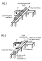
- the average acceleration value at a support point results from the difference between the mean velocity and its predecessor and follower points. An example of a representation of such velocity profiles is shown in FIG.
- the evaluation unit 11 also allows an assignment of signal sources or individual signals to objects or space-time axes. If a signal source has been assigned, then all associated signals of this signal source are assigned to the object. For each assigned signal, it is determined on the basis of the time stamp between or on which movement processes the signal was temporally. Its exact position on the space-time axis can then be calculated by means of an interpolation.
- the signal is displayed for example as a variable-size circular disk which is perpendicular to the space-time axis, supplemented by a text indicating the identifier of the signal. An example of such a representation is shown in FIG.
- a signal can be assigned to more than one object or more than one space-time axis simultaneously. As a result, this is shown several times on different space-time axes. This makes dependencies between movements visible.
- the evaluation unit 11 additionally has the property of being able to continuously change the time stamps of selected signals by a common defined value. This works directly on the display of the signals on the space-time axis.
- the signals are shifted along the space-time axis.
- the optimum position of the sensor 1f can be determined. From the system, the signals of the sensor 1f and the presence of the discharge decision were registered in the controller 4. These signals are brought to display on the associated space-time axis by the association with the object defined by the mark 9b. If the signal of the rejection decision lies behind the rejector, the sensor 1f must be shifted. The time stamp of the reject decision is now changed continuously until the display of the signal comes to rest at the level of the Ausschleusers.
- the sensor signal Since the sensor signal has also been selected to be shifted, it is now at the point where the sensor is to be positioned in order to have the decision signal in time. In this process, preferably the displayed cycle time of the control is taken into account. Interpolation can also be used to calculate interpolation points for a space-time axis that are behind or before the last recorded movement.
- the evaluation unit 11 preferably additionally has the property that the user can define any space-time axis.
- This space-time axis is defined as with an object via a set of motion processes, these motion processes being specified by the user.
Landscapes
- Engineering & Computer Science (AREA)
- Manufacturing & Machinery (AREA)
- General Engineering & Computer Science (AREA)
- Quality & Reliability (AREA)
- Physics & Mathematics (AREA)
- General Physics & Mathematics (AREA)
- Automation & Control Theory (AREA)
- Processing Or Creating Images (AREA)
Applications Claiming Priority (1)
| Application Number | Priority Date | Filing Date | Title |
|---|---|---|---|
| DE102005045855A DE102005045855A1 (de) | 2005-09-26 | 2005-09-26 | Verfahren und Vorrichtung zur Erleichterung der Einstellung von Systemen, bei welchen Objekten bewegt werden |
Publications (3)
| Publication Number | Publication Date |
|---|---|
| EP1768006A2 true EP1768006A2 (fr) | 2007-03-28 |
| EP1768006A3 EP1768006A3 (fr) | 2008-01-16 |
| EP1768006B1 EP1768006B1 (fr) | 2009-02-11 |
Family
ID=37595049
Family Applications (1)
| Application Number | Title | Priority Date | Filing Date |
|---|---|---|---|
| EP06118356A Not-in-force EP1768006B1 (fr) | 2005-09-26 | 2006-08-03 | Système et méthode pour faciliter le réglage de systèmes, avec lesquels des objets sont bougés |
Country Status (2)
| Country | Link |
|---|---|
| EP (1) | EP1768006B1 (fr) |
| DE (2) | DE102005045855A1 (fr) |
Cited By (6)
| Publication number | Priority date | Publication date | Assignee | Title |
|---|---|---|---|---|
| EP2085841A1 (fr) * | 2008-01-31 | 2009-08-05 | Sick Ag | Capteur avec temporisateur à émettre le temps de détection d' un objet |
| EP2434360A1 (fr) * | 2010-09-22 | 2012-03-28 | Siemens Aktiengesellschaft | Système de contrôle de mouvement |
| US20180136035A1 (en) * | 2015-04-20 | 2018-05-17 | Prüftechnik Dieter Busch AG | Method for detecting vibrations of a device and vibration detection system |
| US20200034621A1 (en) * | 2018-07-25 | 2020-01-30 | Fanuc Corporation | Sensing system, work system, augmented-reality-image displaying method, augmented-reality-image storing method, and program |
| US11049287B2 (en) | 2018-08-31 | 2021-06-29 | Fanuc Corporation | Sensing system, work system, augmented-reality-image displaying method, and program |
| EP2729856B1 (fr) * | 2011-07-08 | 2023-03-22 | Intelligrated Headquarters LLC | Technologie de simulation intégrée |
Families Citing this family (3)
| Publication number | Priority date | Publication date | Assignee | Title |
|---|---|---|---|---|
| DE102012217573A1 (de) | 2012-09-27 | 2014-03-27 | Krones Ag | Bediensystem für eine Maschine |
| US20150199106A1 (en) * | 2014-01-14 | 2015-07-16 | Caterpillar Inc. | Augmented Reality Display System |
| DE102014217090B4 (de) | 2014-08-27 | 2022-04-21 | Volkswagen Aktiengesellschaft | Verfahren zum Betrieb eines Augmented-Reality-Systems oder eines Virtual Reality Systems |
Citations (1)
| Publication number | Priority date | Publication date | Assignee | Title |
|---|---|---|---|---|
| EP1447770A2 (fr) | 2003-02-11 | 2004-08-18 | KUKA Roboter GmbH | Procédé et système de visualisation d'information assisté par ordinateur |
Family Cites Families (6)
| Publication number | Priority date | Publication date | Assignee | Title |
|---|---|---|---|---|
| US6625299B1 (en) * | 1998-04-08 | 2003-09-23 | Jeffrey Meisner | Augmented reality technology |
| US6282455B1 (en) * | 1998-10-19 | 2001-08-28 | Rockwell Technologies, Llc | Walk-through human/machine interface for industrial control |
| DE19900884A1 (de) * | 1999-01-12 | 2000-07-20 | Siemens Ag | System und Verfahren zum Bedienen und Beobachten eines Automatisierungssystems mit Prozeßvisualisierung und Prozeßsteuerung durch virtuelle Anlagenmodelle als Abbild einer realen Anlage |
| DE10127396A1 (de) * | 2000-06-13 | 2001-12-20 | Volkswagen Ag | Verfahren zum Verwerten eines Altfahrzeugs |
| DE102004016329A1 (de) * | 2003-11-10 | 2005-05-25 | Siemens Ag | System und Verfahren zur Durchführung und Visualisierung von Simulationen in einer erweiterten Realität |
| US7236854B2 (en) * | 2004-01-05 | 2007-06-26 | Abb Research Ltd. | Method and a system for programming an industrial robot |
-
2005
- 2005-09-26 DE DE102005045855A patent/DE102005045855A1/de not_active Ceased
-
2006
- 2006-08-03 DE DE502006002796T patent/DE502006002796D1/de active Active
- 2006-08-03 EP EP06118356A patent/EP1768006B1/fr not_active Not-in-force
Patent Citations (1)
| Publication number | Priority date | Publication date | Assignee | Title |
|---|---|---|---|---|
| EP1447770A2 (fr) | 2003-02-11 | 2004-08-18 | KUKA Roboter GmbH | Procédé et système de visualisation d'information assisté par ordinateur |
Cited By (8)
| Publication number | Priority date | Publication date | Assignee | Title |
|---|---|---|---|---|
| EP2085841A1 (fr) * | 2008-01-31 | 2009-08-05 | Sick Ag | Capteur avec temporisateur à émettre le temps de détection d' un objet |
| EP2434360A1 (fr) * | 2010-09-22 | 2012-03-28 | Siemens Aktiengesellschaft | Système de contrôle de mouvement |
| EP2729856B1 (fr) * | 2011-07-08 | 2023-03-22 | Intelligrated Headquarters LLC | Technologie de simulation intégrée |
| US20180136035A1 (en) * | 2015-04-20 | 2018-05-17 | Prüftechnik Dieter Busch AG | Method for detecting vibrations of a device and vibration detection system |
| US20200034621A1 (en) * | 2018-07-25 | 2020-01-30 | Fanuc Corporation | Sensing system, work system, augmented-reality-image displaying method, augmented-reality-image storing method, and program |
| US10885340B2 (en) * | 2018-07-25 | 2021-01-05 | Fanuc Corporation | Sensing system, work system, augmented-reality-image displaying method, augmented-reality-image storing method, and program |
| US11328507B2 (en) | 2018-07-25 | 2022-05-10 | Fanuc Corporation | Sensing system, work system, augmented-reality-image displaying method, augmented-reality-image storing method, and program |
| US11049287B2 (en) | 2018-08-31 | 2021-06-29 | Fanuc Corporation | Sensing system, work system, augmented-reality-image displaying method, and program |
Also Published As
| Publication number | Publication date |
|---|---|
| DE502006002796D1 (de) | 2009-03-26 |
| DE102005045855A1 (de) | 2007-03-29 |
| EP1768006A3 (fr) | 2008-01-16 |
| EP1768006B1 (fr) | 2009-02-11 |
Similar Documents
| Publication | Publication Date | Title |
|---|---|---|
| DE102019128814B4 (de) | Kamera zur Erfassung eines Objektstroms und Verfahren zur Bestimmung der Höhe von Objekten | |
| EP2710794B1 (fr) | Procédé pour produire et évaluer une image | |
| DE102018212531B4 (de) | Artikeltransfervorrichtung | |
| DE102018123363A1 (de) | Verfahren zur Kollisionsvermeidung und Laserbearbeitungsmaschine | |
| EP3786745B1 (fr) | Identification des écarts entre une installation réelle et son double numérique | |
| DE102015008195A1 (de) | Gegenstandsausrichtvorrichtung zum Ausrichten von Gegenständen auf einem Förderband | |
| DE112010005042T5 (de) | Dezentrales Bildverarbeitungssystem mit Mehrphasensynchronisierung | |
| EP1768006B1 (fr) | Système et méthode pour faciliter le réglage de systèmes, avec lesquels des objets sont bougés | |
| EP3147089A1 (fr) | Procede de reglage automatise d'un interstice, installation de commande correspondante et dispositif d'estampage | |
| DE10020842A1 (de) | Koordinatenmeßgerät oder Werkzeugmaschine | |
| DE10144998A1 (de) | Ereignisdatenrekorder für Kollisions- bzw. Überlastsituationen an Werkzeugmaschinen | |
| EP1984795A1 (fr) | Procede et dispositif de surveillance d'une ligne de production | |
| WO2006037137A1 (fr) | Surveillance d'une zone de travail pour machines et robots commandes par programme et automatises | |
| EP1701233B1 (fr) | Génération de réalités virtuelles sur la base d'un environnement réel | |
| EP2438491B1 (fr) | Procédé et dispositif pour générer un profil de mouvement variable pour une unité d'entraînement d'une machine | |
| DE102022212433A1 (de) | Verfahren und Vorrichtung zur Sensorüberwachung | |
| DE102016225251A1 (de) | Verfahren und mobile Vorrichtung zur Analyse eines Produktionsablaufes einer Produktionsmaschine, sowie Computerprogramm, Set zur Analyse des Produktionsablaufes der Produktionsmaschine und Koffer | |
| DE102017122627B4 (de) | Optisches Messsystem und Messverfahren | |
| WO2019233551A1 (fr) | Procédé et système pour fournir des protocoles de processus pour des objets physiques | |
| DE19815647C2 (de) | Verfahren zur Synchronisation einer lokalen auf eine zentrale Zeitbasis, und Vorrichtung zur Durchführung des Verfahrens mit bevorzugten Verwendungen | |
| AT518005A1 (de) | Verfahren zur periodischen Erfassung von Messwerten in einem Echtzeitcomputersystem sowie Echtzeitcomputersystem | |
| DE102005060980B4 (de) | Verfahren und System zur Bestimmung eines kollisionsfreien dreidimensionalen Raumvolumens entlang eines Bewegungspfades gegenüber einer realen Umgebung | |
| DE102023116812B4 (de) | Erfassungsanordnung und Verfahren zur Steuerung eines Betriebs einer Erfassungsanordnung | |
| EP4531412B1 (fr) | Capture de flux d'objets à l'aide d'un capteur d'image basé sur des événements | |
| DE102012203987A1 (de) | Verfahren und Vorrichtung zur Visualisierung eines Prozessablaufes in einer hüttentechnischen Anlage |
Legal Events
| Date | Code | Title | Description |
|---|---|---|---|
| PUAI | Public reference made under article 153(3) epc to a published international application that has entered the european phase |
Free format text: ORIGINAL CODE: 0009012 |
|
| AK | Designated contracting states |
Kind code of ref document: A2 Designated state(s): AT BE BG CH CY CZ DE DK EE ES FI FR GB GR HU IE IS IT LI LT LU LV MC NL PL PT RO SE SI SK TR |
|
| AX | Request for extension of the european patent |
Extension state: AL BA HR MK YU |
|
| RIN1 | Information on inventor provided before grant (corrected) |
Inventor name: MORITZ, SOEREN |
|
| PUAL | Search report despatched |
Free format text: ORIGINAL CODE: 0009013 |
|
| AK | Designated contracting states |
Kind code of ref document: A3 Designated state(s): AT BE BG CH CY CZ DE DK EE ES FI FR GB GR HU IE IS IT LI LT LU LV MC NL PL PT RO SE SI SK TR |
|
| AX | Request for extension of the european patent |
Extension state: AL BA HR MK YU |
|
| 17P | Request for examination filed |
Effective date: 20080411 |
|
| GRAP | Despatch of communication of intention to grant a patent |
Free format text: ORIGINAL CODE: EPIDOSNIGR1 |
|
| AKX | Designation fees paid |
Designated state(s): DE FR GB IT |
|
| GRAS | Grant fee paid |
Free format text: ORIGINAL CODE: EPIDOSNIGR3 |
|
| GRAS | Grant fee paid |
Free format text: ORIGINAL CODE: EPIDOSNIGR3 |
|
| GRAA | (expected) grant |
Free format text: ORIGINAL CODE: 0009210 |
|
| AK | Designated contracting states |
Kind code of ref document: B1 Designated state(s): DE FR GB IT |
|
| REG | Reference to a national code |
Ref country code: GB Ref legal event code: FG4D Free format text: NOT ENGLISH |
|
| REF | Corresponds to: |
Ref document number: 502006002796 Country of ref document: DE Date of ref document: 20090326 Kind code of ref document: P |
|
| PLBE | No opposition filed within time limit |
Free format text: ORIGINAL CODE: 0009261 |
|
| STAA | Information on the status of an ep patent application or granted ep patent |
Free format text: STATUS: NO OPPOSITION FILED WITHIN TIME LIMIT |
|
| 26N | No opposition filed |
Effective date: 20091112 |
|
| REG | Reference to a national code |
Ref country code: FR Ref legal event code: PLFP Year of fee payment: 11 |
|
| REG | Reference to a national code |
Ref country code: FR Ref legal event code: PLFP Year of fee payment: 12 |
|
| REG | Reference to a national code |
Ref country code: FR Ref legal event code: PLFP Year of fee payment: 13 |
|
| PGFP | Annual fee paid to national office [announced via postgrant information from national office to epo] |
Ref country code: DE Payment date: 20181019 Year of fee payment: 13 |
|
| PGFP | Annual fee paid to national office [announced via postgrant information from national office to epo] |
Ref country code: IT Payment date: 20190828 Year of fee payment: 14 Ref country code: FR Payment date: 20190823 Year of fee payment: 14 |
|
| PGFP | Annual fee paid to national office [announced via postgrant information from national office to epo] |
Ref country code: GB Payment date: 20190805 Year of fee payment: 14 |
|
| REG | Reference to a national code |
Ref country code: DE Ref legal event code: R119 Ref document number: 502006002796 Country of ref document: DE |
|
| PG25 | Lapsed in a contracting state [announced via postgrant information from national office to epo] |
Ref country code: DE Free format text: LAPSE BECAUSE OF NON-PAYMENT OF DUE FEES Effective date: 20200303 |
|
| GBPC | Gb: european patent ceased through non-payment of renewal fee |
Effective date: 20200803 |
|
| PG25 | Lapsed in a contracting state [announced via postgrant information from national office to epo] |
Ref country code: FR Free format text: LAPSE BECAUSE OF NON-PAYMENT OF DUE FEES Effective date: 20200831 |
|
| PG25 | Lapsed in a contracting state [announced via postgrant information from national office to epo] |
Ref country code: GB Free format text: LAPSE BECAUSE OF NON-PAYMENT OF DUE FEES Effective date: 20200803 |
|
| PG25 | Lapsed in a contracting state [announced via postgrant information from national office to epo] |
Ref country code: IT Free format text: LAPSE BECAUSE OF NON-PAYMENT OF DUE FEES Effective date: 20200803 |