EP1768009A1 - Drehsteller - Google Patents
Drehsteller Download PDFInfo
- Publication number
- EP1768009A1 EP1768009A1 EP06008070A EP06008070A EP1768009A1 EP 1768009 A1 EP1768009 A1 EP 1768009A1 EP 06008070 A EP06008070 A EP 06008070A EP 06008070 A EP06008070 A EP 06008070A EP 1768009 A1 EP1768009 A1 EP 1768009A1
- Authority
- EP
- European Patent Office
- Prior art keywords
- turntable
- housing
- turntable according
- rotor
- electric motor
- Prior art date
- Legal status (The legal status is an assumption and is not a legal conclusion. Google has not performed a legal analysis and makes no representation as to the accuracy of the status listed.)
- Granted
Links
Images
Classifications
-
- G—PHYSICS
- G01—MEASURING; TESTING
- G01D—MEASURING NOT SPECIALLY ADAPTED FOR A SPECIFIC VARIABLE; ARRANGEMENTS FOR MEASURING TWO OR MORE VARIABLES NOT COVERED IN A SINGLE OTHER SUBCLASS; TARIFF METERING APPARATUS; MEASURING OR TESTING NOT OTHERWISE PROVIDED FOR
- G01D5/00—Mechanical means for transferring the output of a sensing member; Means for converting the output of a sensing member to another variable where the form or nature of the sensing member does not constrain the means for converting; Transducers not specially adapted for a specific variable
- G01D5/12—Mechanical means for transferring the output of a sensing member; Means for converting the output of a sensing member to another variable where the form or nature of the sensing member does not constrain the means for converting; Transducers not specially adapted for a specific variable using electric or magnetic means
- G01D5/14—Mechanical means for transferring the output of a sensing member; Means for converting the output of a sensing member to another variable where the form or nature of the sensing member does not constrain the means for converting; Transducers not specially adapted for a specific variable using electric or magnetic means influencing the magnitude of a current or voltage
- G01D5/142—Mechanical means for transferring the output of a sensing member; Means for converting the output of a sensing member to another variable where the form or nature of the sensing member does not constrain the means for converting; Transducers not specially adapted for a specific variable using electric or magnetic means influencing the magnitude of a current or voltage using Hall-effect devices
- G01D5/145—Mechanical means for transferring the output of a sensing member; Means for converting the output of a sensing member to another variable where the form or nature of the sensing member does not constrain the means for converting; Transducers not specially adapted for a specific variable using electric or magnetic means influencing the magnitude of a current or voltage using Hall-effect devices influenced by the relative movement between the Hall device and magnetic fields
-
- B—PERFORMING OPERATIONS; TRANSPORTING
- B60—VEHICLES IN GENERAL
- B60K—ARRANGEMENT OR MOUNTING OF PROPULSION UNITS OR OF TRANSMISSIONS IN VEHICLES; ARRANGEMENT OR MOUNTING OF PLURAL DIVERSE PRIME-MOVERS IN VEHICLES; AUXILIARY DRIVES FOR VEHICLES; INSTRUMENTATION OR DASHBOARDS FOR VEHICLES; ARRANGEMENTS IN CONNECTION WITH COOLING, AIR INTAKE, GAS EXHAUST OR FUEL SUPPLY OF PROPULSION UNITS IN VEHICLES
- B60K35/00—Instruments specially adapted for vehicles; Arrangement of instruments in or on vehicles
- B60K35/10—Input arrangements, i.e. from user to vehicle, associated with vehicle functions or specially adapted therefor
-
- B—PERFORMING OPERATIONS; TRANSPORTING
- B60—VEHICLES IN GENERAL
- B60K—ARRANGEMENT OR MOUNTING OF PROPULSION UNITS OR OF TRANSMISSIONS IN VEHICLES; ARRANGEMENT OR MOUNTING OF PLURAL DIVERSE PRIME-MOVERS IN VEHICLES; AUXILIARY DRIVES FOR VEHICLES; INSTRUMENTATION OR DASHBOARDS FOR VEHICLES; ARRANGEMENTS IN CONNECTION WITH COOLING, AIR INTAKE, GAS EXHAUST OR FUEL SUPPLY OF PROPULSION UNITS IN VEHICLES
- B60K35/00—Instruments specially adapted for vehicles; Arrangement of instruments in or on vehicles
- B60K35/20—Output arrangements, i.e. from vehicle to user, associated with vehicle functions or specially adapted therefor
- B60K35/25—Output arrangements, i.e. from vehicle to user, associated with vehicle functions or specially adapted therefor using haptic output
-
- F—MECHANICAL ENGINEERING; LIGHTING; HEATING; WEAPONS; BLASTING
- F16—ENGINEERING ELEMENTS AND UNITS; GENERAL MEASURES FOR PRODUCING AND MAINTAINING EFFECTIVE FUNCTIONING OF MACHINES OR INSTALLATIONS; THERMAL INSULATION IN GENERAL
- F16H—GEARING
- F16H59/00—Control inputs to control units of change-speed- or reversing-gearings for conveying rotary motion
- F16H59/02—Selector apparatus
- F16H59/08—Range selector apparatus
-
- G—PHYSICS
- G05—CONTROLLING; REGULATING
- G05G—CONTROL DEVICES OR SYSTEMS INSOFAR AS CHARACTERISED BY MECHANICAL FEATURES ONLY
- G05G1/00—Controlling members, e.g. knobs or handles; Assemblies or arrangements thereof; Indicating position of controlling members
- G05G1/08—Controlling members for hand actuation by rotary movement, e.g. hand wheels
- G05G1/087—Controlling members for hand actuation by rotary movement, e.g. hand wheels retractable; Flush control knobs
-
- H—ELECTRICITY
- H01—ELECTRIC ELEMENTS
- H01H—ELECTRIC SWITCHES; RELAYS; SELECTORS; EMERGENCY PROTECTIVE DEVICES
- H01H3/00—Mechanisms for operating contacts
- H01H3/02—Operating parts, i.e. for operating driving mechanism by a mechanical force external to the switch
- H01H3/08—Turn knobs
-
- B—PERFORMING OPERATIONS; TRANSPORTING
- B60—VEHICLES IN GENERAL
- B60K—ARRANGEMENT OR MOUNTING OF PROPULSION UNITS OR OF TRANSMISSIONS IN VEHICLES; ARRANGEMENT OR MOUNTING OF PLURAL DIVERSE PRIME-MOVERS IN VEHICLES; AUXILIARY DRIVES FOR VEHICLES; INSTRUMENTATION OR DASHBOARDS FOR VEHICLES; ARRANGEMENTS IN CONNECTION WITH COOLING, AIR INTAKE, GAS EXHAUST OR FUEL SUPPLY OF PROPULSION UNITS IN VEHICLES
- B60K2360/00—Indexing scheme associated with groups B60K35/00 or B60K37/00 relating to details of instruments or dashboards
- B60K2360/126—Rotatable input devices for instruments
-
- F—MECHANICAL ENGINEERING; LIGHTING; HEATING; WEAPONS; BLASTING
- F16—ENGINEERING ELEMENTS AND UNITS; GENERAL MEASURES FOR PRODUCING AND MAINTAINING EFFECTIVE FUNCTIONING OF MACHINES OR INSTALLATIONS; THERMAL INSULATION IN GENERAL
- F16H—GEARING
- F16H59/00—Control inputs to control units of change-speed- or reversing-gearings for conveying rotary motion
- F16H59/02—Selector apparatus
- F16H59/08—Range selector apparatus
- F16H2059/081—Range selector apparatus using knops or discs for rotary range selection
-
- H—ELECTRICITY
- H01—ELECTRIC ELEMENTS
- H01H—ELECTRIC SWITCHES; RELAYS; SELECTORS; EMERGENCY PROTECTIVE DEVICES
- H01H3/00—Mechanisms for operating contacts
- H01H3/02—Operating parts, i.e. for operating driving mechanism by a mechanical force external to the switch
- H01H2003/0266—Operating part bringable in an inoperative position by an electrical drive
-
- H—ELECTRICITY
- H01—ELECTRIC ELEMENTS
- H01H—ELECTRIC SWITCHES; RELAYS; SELECTORS; EMERGENCY PROTECTIVE DEVICES
- H01H3/00—Mechanisms for operating contacts
- H01H3/02—Operating parts, i.e. for operating driving mechanism by a mechanical force external to the switch
- H01H3/08—Turn knobs
- H01H2003/085—Retractable turn knobs, e.g. flush mounted
Definitions
- the invention relates to a turntable with a rotatably mounted actuating shaft and an associated, arranged in a user interface knob, as well as with a locking cam and at least one engaging in the latching cam locking bolt comprehensive mechanical locking device.
- Turntables are used for example in data input devices in which by turning the turntable and possibly by pressing or pivoting the same about a cursor control in different menu levels can be performed.
- a turntable may be part of a so-called joystick.
- Such a turntable is known from the DE 197 12 049 A1 ,
- a device for generating a haptic is geared to the actuating shaft coupled.
- it is an electric motor, which acts accordingly applied to the rotary shaft opposite torque on the actuating shaft.
- the electric motor which acts accordingly applied to the rotary shaft opposite torque on the actuating shaft.
- different haptics can be provided.
- the turntable according to the present invention is further developed with respect to those known from the prior art described to allow an active adjustment of the knob between a position of use and a non-use position thereof.
- knob is associated with an actuator driven by an electric motor, by means of which it is axially adjustable between an outstanding position from the user interface and a recessed position in the user interface.
- the detent recesses of the detent curve form sections in the axial direction extending tracks that allow a displacement of the control shaft in the direction of its axis of rotation, and that at the end remote from the user interface of these webs extending obliquely to this, a forced coupling is provided by rotational movement and axial displacement of the actuating shaft causing further path in the latching cam.
- an angle measuring device is provided with which the exact rotational position of the control shaft can be detected.
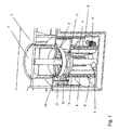
- the turntable shown in the drawing is taken up to the one provided for manual operation knob 1 in a housing 7, which is shown partially open in FIG.
- a rotatably mounted in the housing 7 actuating shaft 3, passes through the housing 7 on its user interface 2 and connects the knob 1 with a Haptiker Wegungs announced.
- the knob is located in Fig. 1 in a position in which the vehicle can be taken out of service, ie in the so-called P position corresponding to the park position of the transmission.
- the knob 1 is in this position with its top flush with the user interface 2.
- the connected to the knob 1 haptic generating device is designed in the manner of a mechanical detent and essentially comprises an at least partially annular detent curve 4 and two engaging in this spring-loaded detent pin 5.
- Die two locking pins 5 are arranged opposite one another in a connected to the control shaft 3 and arranged in a direction perpendicular to the axis of rotation thereof, sleeve-like receptacle by a compression spring.
- the latching cam 4 is arranged on the inside of a cup-shaped part of the housing 7.
- the latching recesses of the latching cam 4 form sections 4 'extending in the axial direction, which allow a displacement of the control shaft 3 in the direction of its axis of rotation.
- the knob 1 is connected to an adjusting device by which he between his from the user interface 2 outstanding, a rotation of the same permitting use position and a sunken in the user interface 2 rotation of the same preventing non-use position is adjustable.
- a cylindrical rotor 8 is rotatably received in the cup-shaped part of the housing 7, which is driven by an electric motor. Also included in the cup-shaped part of the housing 7 and that against rotation and axially displaceable to this is a stator 9.
- This stator in turn is rotatably and axially fixedly connected to the control shaft 3 of the knob 1.
- the rotor 8 and the stator 9 are engaged with each other via a thread-like coupling by which they cooperate with each other in a manner converting a rotational movement of the rotor 8 in an axial movement of the stator 9.
- the rotor 8 is engaged via a peripheral external toothing 8 'by means of a geared connection with an electric motor 6 arranged below in the housing 7.
- the axis of the electric motor 6 is for this purpose provided with a worm wheel 6 ', which engages in the designed as a helical spur peripheral outer toothing 8' of the rotor 8.
- the knob 1 In its normal position of use, the knob 1 protrudes from the user interface 2 and is thus accessible to the user. A rotation of the knob 1 in its various positions is possible against the latching forces of the latching device and thus under experience of the haptic generated therewith.
- the rotor 8 is rotated by means of the electric motor 6 via its worm wheel 6 '.
- the stator 9 is moved by the rotational movement of the rotor 8 in the axial direction, and thereby the knob 1 is retracted into the user interface 2 inside.
- a particularly low-friction thread-like coupling between the rotor 8 and stator 9, which also allows a low overall height of the entire structure is projecting through a three-start trapezoidal thread on the outside of the stator 9 and three at an angular distance of 120 ° from the inside of the rotor 8 and realized in this thread engaging, also trapezoidal executed pins.
- the latching pins 5 of the latching device strike the track 4 "which extends at an angle to the axially aligned tracks 4 'of the latching cam 4 another axial movement of the control shaft 3 causes a rotation of the same, so that the knob 1 is not only pulled into the user interface 2 in but simultaneously displaced in its rotational position and thus also with respect to this rotational position in a defined rest or non-use position is brought.
- brake brackets 11 are mounted in an area above the latching device provided in cooperation with a corresponding to the desired locking positions contour with the Control shaft 3 rotatably connected locking disc 12 can prevent rotation of the control shaft 3.
- the brake clips 11 are moved by a solenoid 13 to the control shaft 3, and thereby brought to the brake clips 11 pins with corresponding recesses in the contour of the locking disc 12 is engaged.
- an electronic control device is provided, which is at least partially realized on a above the haptic generating device, the control shaft 3 encompassing arranged printed circuit board 10. Also on this circuit board 10, the fixed sensing elements of an angle measuring device for detecting the rotational position of the control shaft 3 are present. These cooperate with corresponding initiator elements, which are rotatably connected to the control shaft 3 and rotate with this with respect to the fixed circuit board 10 and connected to this sensing elements.
- These stationary scanning elements and the initiator elements assigned to them can be, for example, light barriers which cooperate with diaphragm or reflection elements, or about Hall effect or magnetoresistive sensors which cooperate with correspondingly designed magnet structures.
Landscapes
- Engineering & Computer Science (AREA)
- Mechanical Engineering (AREA)
- Physics & Mathematics (AREA)
- General Physics & Mathematics (AREA)
- General Engineering & Computer Science (AREA)
- Chemical & Material Sciences (AREA)
- Combustion & Propulsion (AREA)
- Transportation (AREA)
- Automation & Control Theory (AREA)
- Mechanical Control Devices (AREA)
- Connection Of Motors, Electrical Generators, Mechanical Devices, And The Like (AREA)
Abstract
Description
- Die Erfindung betrifft einen Drehsteller mit einer drehbar gelagerten Stellwelle und einem damit verbundenen, in einer Bedienoberfläche angeordneten Drehknopf, sowie mit einer eine Rastkurve und zumindest einen in die Rastkurve eingreifenden Rastbolzen umfassenden mechanischen Rasteinrichtung.
- Drehsteller werden beispielsweise bei Dateneingabegeräten eingesetzt, bei denen durch Drehen des Drehstellers und gegebenenfalls durch Drücken oder Verschwenken desselben etwa eine Cursorsteuerung in unterschiedlichen Menüebenen durchgeführt werden kann. Beispielsweise kann ein solcher Drehsteller Teil eines sogenannten Joysticks sein. Ein solcher Drehsteller ist bekannt aus der
DE 197 12 049 A1 . Bei diesem vorbekannten Drehsteller ist getrieblich mit der Stellwelle eine Einrichtung zum Erzeugen einer Haptik gekoppelt. Bei dieser Einrichtung handelt es sich um einen Elektromotor, der entsprechend beaufschlagt ein der Drehbewegung entgegengesetztes Drehmoment auf die Stellwelle ausübt. In Abhängigkeit von der Ansteuerung bzw. Aktivierung des Elektromotors sowohl hinsichtlich der den Elektromotor beaufschlagenden Stromstärke als auch in Abhängigkeit von der aktuellen Drehwinkelstellung der Stellwelle können unterschiedliche Haptiken bereitgestellt werden. - Durch die
DE 100 41 935 A1 ist ein Drehsteller bekannt geworden, bei dem mehrere ringförmig angeordnete Rastkurven übereinander angeordnet und zur Erzeugung unterschiedlicher Haptiken wahlweise durch elektromagnetisch betätigbare Spannringe aktivierbar sind. Mit dieser Einrichtung werden die zuvor genannten Nachteile bezüglich des zu schwammigen Gefühls der elektromotorisch erzeugten Haptik überwunden. - Der Drehsteller gemäß der vorliegenden Erfindung ist gegenüber den aus dem beschriebenen Stand der Technik bekannten dahingehend weitergebildet eine aktive Verstellung des Drehknopfes zwischen einer Gebrauchsstellung und einer Nichtgebrauchsstellung desselben zu ermöglichen.
- Dies wird erfindungsgemäß dadurch möglich, daß dem Drehknopf eine durch einen Elektromotor angetriebene Stelleinrichtung zugeordnet ist, mittels derer dieser zwischen einer aus der Bedienoberfläche herausragenden Position und einer in der Bedienoberfläche versenkten Position axial verstellbar ist.
- In einem bevorzugten Ausführungsbeispiel ist vorgesehen, daß die Rastvertiefungen der Rastkurve abschnittsweise in axialer Richtung sich erstreckende Bahnen ausbilden, die eine Verschiebung der Stellwelle in Richtung ihrer Drehachse ermöglichen, und daß an dem der Bedienoberfläche abgewandten Ende dieser Bahnen eine schräg zu diesen verlaufende, eine Zwangskopplung von Drehbewegung und axialer Verschiebung der Stellwelle bewirkende weitere Bahn in der Rastkurve vorhanden ist. Durch diese Ausgestaltung ist es möglich, gleichzeitig mit dem axialen Verstellen des Drehknopfes in seine versenkte Nichtgebrauchsstellung das Einnehmen einer vorbestimmten Drehstellung sicher zu stellen.
- In einer Weiterbildung der Erfindung ist vorgesehen, daß in dem Gehäuse eine Winkelmesseinrichtung vorhanden ist, mit der die exakte Drehstellung der Stellwelle erfasst werden kann.
- Nachfolgend ist die Erfindung anhand eines Ausführungsbeispiels unter Bezugnahme auf die beigefügten Figuren erläutert. Bei diesem Ausführungsbeispiel handelt es sich um eine Anwendung des erfindungsgemäßen Drehstellers als manuelle Eingabeeinrichtung für ein automatisches Getriebe eines Kraftfahrzeugs. Es zeigen:
- Fig.1:
- Eine dreidimensionale Darstellung eines erfindungsgemäßen Drehstellers
- Fig. 2:
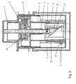
- Einen Längsschnitt durch den Drehsteller der Figur 1
- Der in der Zeichnung dargestellte Drehsteller ist bis auf den zur manuellen Bedienung vorgesehenen Drehknopf 1 in einem Gehäuse 7 aufgenommen, das in der Fig. 1 teilweise geöffnet dargestellt ist. Eine in dem Gehäuse 7 drehbar gelagerte Stellwelle 3, durchgreift das Gehäuse 7 an seiner Bedienoberfläche 2 und verbindet den Drehknopf 1 mit einer Haptikerzeugungseinrichtung. Der Drehknopf befindet sich in Fig. 1 in einer Stellung in der das Fahrzeug außer Betrieb genommen werden kann, d.h. in der so genannten P-Stellung, die der Park-Stellung des Getriebes entspricht. Der Drehknopf 1 ist in dieser Stellung mit seiner Oberseite bündig mit der Bedienoberfläche 2. Die mit dem Drehknopf 1 verbundene Haptikerzeugungseinrichtung ist nach Art einer mechanischen Rastung ausgeführt und umfasst im wesentlichen eine zumindest abschnittsweise ringförmige Rastkurve 4 sowie zwei in diese eingreifende federbelastete Rastbolzen 5. Die beiden Rastbolzen 5 sind einander gegenüberliegend in einer mit der Stellwelle 3 verbundenen und in einer senkrecht zur Drehachse derselben angeordneten, hülsenartigen Aufnahme durch eine Druckfeder sich gegenseitig abstützend angeordnet. Die Rastkurve 4 ist auf der Innenseite eines topfförmigen Teils des Gehäuses 7 angeordnet.
Die Rastvertiefungen der Rastkurve 4 bilden abschnittsweise in axialer Richtung sich erstreckende Bahnen 4' aus, die eine Verschiebung der Stellwelle 3 in Richtung ihrer Drehachse ermöglichen. An dem der Bedienoberfläche 2 abgewandten Ende dieser Bahnen 4' ist eine schräg zu diesen verlaufende, eine Zwangskopplung von Drehbewegung und axialer Verschiebung der Stellwelle 3 bewirkende weitere Bahn 4" in der Rastkurve 4 vorhanden. - Der Drehknopf 1 ist mit einer Stelleinrichtung verbunden durch welche er zwischen seiner aus der Bedienoberfläche 2 herausragenden, eine Drehung desselben erlaubenden Gebrauchsstellung und einer in der Bedienoberfläche 2 versenkte eine Drehung desselben verhindernde Nichtgebrauchsstellung verstellbar ist.
- Dazu ist in dem topfförmigen Teil des Gehäuses 7 ein zylindrischer Rotor 8 drehbar aufgenommenen, der durch einen Elektromotor antreibbar ist. Ebenfalls in dem topfförmigen Teil des Gehäuses 7 aufgenommen und zwar drehfest und axial verschiebbar zu diesem ist ein Stator 9. Dieser Stator wiederum ist mit der Stellwelle 3 des Drehknopfes 1 drehbeweglich und axial fest verbunden. Der Rotor 8 und der Stator 9 sind über eine gewindeartige Kopplung miteinander in Eingriff gestellt, durch die diese in einer eine Drehbewegung des Rotors 8 in eine axiale Bewegung des Stators 9 umsetzenden Weise miteinander kooperieren.
- Der Rotor 8 ist über eine umlaufende Außenverzahnung 8' mittels einer getrieblichen Verbindung mit einem unten im Gehäuse 7 angeordneten Elektromotor 6 in Eingriff gestellt. Die Achse des Elektromotors 6 ist dazu mit einem Schneckenrad 6' versehen, welches ein in die als schrägverzahntes Stirnrad ausgeführte umlaufende Außenverzahnung 8' des Rotors 8 eingreift.
- In seiner normalen Gebrauchsstellung ragt der Drehknopf 1 aus der Bedienoberfläche 2 heraus und ist so für den Benutzer greifbar. Eine Drehung des Knopfes 1 in seine verschiedenen Positionen ist gegen die Rastkräfte der Rasteinrichtung und damit unter Erfahrung der damit erzeugten Haptik möglich.
- Soll die durch den Drehsteller beeinflussbare elektrische Einrichtung außer Funktion gesetzt werden, so wird zuvor der Drehknopf 1 in seine Nichtgebrauchsstellung verlagert. Dazu wird mittels des Elektromotors 6 über sein Schneckenrad 6' der Rotor 8 in Drehung versetzt. Über die gewindeartige Kopplung zwischen Rotor 8 und Stator 9 wird der Stator 9 durch die Drehbewegung des Rotors 8 in axialer Richtung bewegt, und dadurch der Drehknopf 1 in die Bedienoberfläche 2 hinein zurückgezogen. Eine besonders reibungsarme gewindeartige Kopplung zwischen Rotor 8 und Stator 9, die zudem auch eine geringe Bauhöhe des gesamten Aufbaus ermöglicht, ist durch ein dreigängiges Trapezgewinde an der Aussenseite des Stators 9 sowie drei in einem Winkelabstand von jeweils 120° von der Innenseite des Rotors 8 abragende und in dieses Gewinde eingreifende, ebenfalls trapezförmig ausgeführte Stifte realisiert. Bei der axialen Bewegung des Drehknopfes 1 sowie der mit diesem verbundenen Stellwelle 3 treffen die Rastbolzen 5 der Rasteinrichtung auf die am Ende der axial ausgerichteten Bahnen 4' der Rastkurve 4 angeordnete schräg zu diesen verlaufende Bahn 4". Durch diese Bahn 4" wird bei der weiteren axialen Bewegung der Stellwelle 3 auch eine Drehung derselben bewirkt, so daß der Drehknopf 1 nicht nur in die Bedienoberfläche 2 hinein gezogen sondern gleichzeitig auch in seiner Drehstellung verlagert und damit auch bezüglich dieser Drehstellung in eine definierte Ruhe- oder Nichtgebrauchsstellung gebracht wird.
- In dieser Nichtgebrauchsstellung des Drehknopfes 1 ist eine Verdrehung desselben verhindert, da in seiner zurückgezogenen axialen Stellung nur eine einzige Drehstellung in der Rastkurve 4 einnehmbar ist. Bei einer erneuten Inbetriebnahme der Einrichtung wird der Elektromotor 6 in der entgegengesetzten Richtung betrieben, wodurch der Drehknopf 1 wieder in seine aus der Bedienoberfläche 2 herausragende Stellung verlagert wird. Seine Drehstellung bleibt dabei in der zuletzt eingenommenen Position, da sich die Rastbolzen 5 lediglich entlang der letzten der axial ausgerichteten Bahnen 4' bewegen. Die anfängliche Drehstellung des Drehknopfes 1 bei einer Inbetriebnahme der Einrichtung entspricht somit stets der in der Nichtgebrauchsstellung eingenommenen.
- Um den Drehknopf 1 in seiner Nichtgebrauchsstellung zusätzlich gegen Verdrehung zu sichern oder auch um in anderen Positionen einer Drehsperre zu ermöglichen, sind in einem Bereich oberhalb der Rasteinrichtung Bremsklammern 11 angebracht, die in Kooperation mit einer mit einer den gewünschten Sperrpositionen entsprechenden Kontur versehenen, mit der Stellwelle 3 drehfest verbundenen Sperrscheibe 12 eine Drehung der Stellwelle 3 verhindern können. Um eine solche Drehsperre zu aktivieren werden die Bremsklammern 11 durch eine Magnetspule 13 auf die Stellwelle 3 zu bewegt, und dabei an den Bremsklammern 11 vorhandene Zapfen mit entsprechenden Ausnehmungen in der Kontur der Sperrscheibe 12 in Eingriff gebracht.
- Zur Steuerung des Drehstellers ist im Gehäuse 7 eine elektronische Steuereinrichtung vorhanden, die zumindest teilweise auf einer oberhalb der Haptikerzeugungseinrichtung die Stellwelle 3 umgreifend angeordneten Leiterplatte 10 realisiert ist. Ebenfalls auf dieser Leiterplatte 10 sind die feststehenden Abtastelemente einer Winkelmesseinrichtung zur Erfassung der Drehstellung der Stellwelle 3 vorhanden. Diese kooperieren mit entsprechenden Initiatorelementen, die mit der Stellwelle 3 drehfest verbunden sind und sich mit dieser in Bezug auf die feststehende Leiterplatte 10 und die mit dieser verbundenen Abtastelemente drehen. Bei diesen feststehenden Abtastelementen und den diesen zugeordneten Initiatorelementen kann es sich beispielweise um Lichtschranken handeln, die mit Blenden- oder Reflexionselementen kooperieren, oder etwa um Halleffekt- bzw. magnetoresistive Sensoren, die mit entsprechend ausgebildeten Magnetstrukturen kooperieren.
-
- 1
- Drehknopf
- 2
- Bedienoberfläche
- 3
- Stellwelle
- 4
- Rastkurve
- 4'
- axial verlaufende Bahn
- 4"
- schräg verlaufende Bahn
- 5
- Rastbolzen
- 6
- Elektromotor
- 6'
- Schneckenrad
- 7
- Gehäuse
- 8
- Rotor
- 8'
- Außenverzahnung
- 9
- Stator
- 10
- Leiterplatte
- 11
- Bremsklammer
- 12
- Sperrscheibe
- 13
- Magnetspule
Claims (8)
- Drehsteller mit einer drehbar gelagerten Stellwelle (3) und einem damit verbundenen, in einer Bedienoberfläche (2) angeordneten Drehknopf (1), sowie mit einer eine Rastkurve (4) und zumindest einen in die Rastkurve (4) eingreifenden Rastbolzen (5) umfassenden mechanischen Rasteinrichtung, dadurch gekennzeichnet, daß dem Drehknopf (1) eine durch einen Elektromotor (6) angetriebene Stelleinrichtung zugeordnet ist, mittels derer dieser zwischen einer aus der Bedienoberfläche (2) herausragenden Position und einer in der Bedienoberfläche (2) versenkten Position axial verstellbar ist.
- Drehsteller nach Anspruch 1, dadurch gekennzeichnet, daß die Stelleinrichtung einen in einem topfförmigen Teil eines Gehäuses (7) drehbar aufgenommenen, durch den Elektromotor antreibbaren, zylindrischen Rotor (8) sowie einen in dem Gehäuse (7) drehfest und axial verschiebbar aufgenommenen, mit der Stellwelle (3) des Drehknopfes (1) drehbeweglich und axial fest verbundenen Stator (9) umfasst, wobei Rotor (8) und Stator (9) mittels einer eine Drehbewegung des Rotors (8) in eine axiale Bewegung des Stators (9) umsetzenden gewindeartigen Kopplung miteinander kooperieren.
- Drehsteller nach Anspruch 2, dadurch gekennzeichnet, daß der Rotor (8) auf seiner Außenseite eine umlaufende Außenverzahnung (8') aufweist, und über diese mittels eines Zahnradgetriebes mit dem Elektromotor in Eingriff ist.
- Drehsteller nach einem der Ansprüche 1 bis 3, dadurch gekennzeichnet, daß die Rastvertiefungen der Rastkurve (4) abschnittsweise in axialer Richtung sich erstreckende Bahnen (4') ausbilden, die eine Verschiebung der Stellwelle (3) in Richtung ihrer Drehachse ermöglichen, und daß an dem der Bedienoberfläche (2) abgewandten Ende dieser Bahnen (4') eine schräg zu diesen verlaufende, eine Zwangskopplung von Drehbewegung und axialer Verschiebung der Stellwelle (3) bewirkende weitere Bahn (4") in der Rastkurve (4) vorhanden ist.
- Drehsteller nach einem der Ansprüche 1 bis 4, dadurch gekennzeichnet, daß Drehknopf (1) in seiner aus der Bedienoberfläche (2) herausragenden Position in einer eine Drehung desselben erlaubenden Gebrauchsstellung und seiner in der Bedienoberfläche (2) versenkten Position in einer eine Drehung desselben verhindernden Nichtgebrauchsstellung ist
- Drehsteller nach einem der Ansprüche 1 bis 5, dadurch gekennzeichnet, daß zur Steuerung des Drehstellers im Gehäuse (7) eine elektronische Steuereinrichtung vorhanden ist, die auf einer oberhalb der Rastseinrichtung die Stellwelle (3) zumindest teilweise umgreifend angeordneten Leiterplatte (10) realisiert ist.
- Drehsteller nach einem der Ansprüche 1 bis 6, dadurch gekennzeichnet, daß in dem Gehäuse (7) eine Winkelmesseinrichtung zur Erfassung der Drehstellung der Stellwelle (3) vorhanden ist.
- Drehsteller nach Anspruch 7, dadurch gekennzeichnet, daß die Winkelmesseinrichtung auf der Leiterplatte (10) angeordnete, feststehende Abtastelemente und mit der Stellwelle (3) drehfest verbundene und sich mit dieser in Bezug auf die feststehende Leiterplatte (10) drehende Initiatorelemente umfaßt.
Applications Claiming Priority (1)
| Application Number | Priority Date | Filing Date | Title |
|---|---|---|---|
| DE102005018380A DE102005018380A1 (de) | 2005-04-21 | 2005-04-21 | Drehsteller |
Publications (2)
| Publication Number | Publication Date |
|---|---|
| EP1768009A1 true EP1768009A1 (de) | 2007-03-28 |
| EP1768009B1 EP1768009B1 (de) | 2010-06-02 |
Family
ID=37111209
Family Applications (1)
| Application Number | Title | Priority Date | Filing Date |
|---|---|---|---|
| EP06008070A Expired - Lifetime EP1768009B1 (de) | 2005-04-21 | 2006-04-19 | Drehsteller |
Country Status (3)
| Country | Link |
|---|---|
| EP (1) | EP1768009B1 (de) |
| AT (1) | ATE470181T1 (de) |
| DE (2) | DE102005018380A1 (de) |
Cited By (6)
| Publication number | Priority date | Publication date | Assignee | Title |
|---|---|---|---|---|
| EP2159455A1 (de) | 2008-08-28 | 2010-03-03 | Dura Automotive Systems SAS | Steuervorrichtung eines computergesteuerten Kraftfahrzeuggetriebes |
| DE102009001936A1 (de) * | 2009-03-27 | 2010-09-30 | BSH Bosch und Siemens Hausgeräte GmbH | Bedieneinrichtung für ein Hausgerät |
| CN108317242A (zh) * | 2018-04-21 | 2018-07-24 | 浙江科思泰智能科技有限公司 | 旋钮换挡器的旋钮升降系统 |
| US20190203832A1 (en) * | 2017-12-29 | 2019-07-04 | Sl Corporation | Actuator and vehicle transmission including the same |
| US10865875B2 (en) * | 2018-08-21 | 2020-12-15 | Kyung Chang Industrial Co., Ltd. | Dial shift lever device for vehicle |
| US10948056B2 (en) | 2017-12-23 | 2021-03-16 | Continental Automotive Systems, Inc. | Elevation mechanism for a central input selector knob |
Families Citing this family (4)
| Publication number | Priority date | Publication date | Assignee | Title |
|---|---|---|---|---|
| DE102009001935A1 (de) * | 2009-03-27 | 2010-09-30 | BSH Bosch und Siemens Hausgeräte GmbH | Bedieneinrichtung für ein Hausgerät |
| EP3020896A1 (de) * | 2014-11-12 | 2016-05-18 | Illinois Tool Works Inc. | Tastvorrichtung mit Einstellfunktion zur Anwendung in einem Fahrzeug |
| DE102019114111A1 (de) * | 2019-05-27 | 2020-12-03 | Bayerische Motoren Werke Aktiengesellschaft | Wahlregler für eine Audioeinheit, Audioeinheit und Fahrzeug |
| WO2025149769A1 (en) * | 2024-01-08 | 2025-07-17 | Ka Group Ag | Retractable rotary control knob |
Citations (4)
| Publication number | Priority date | Publication date | Assignee | Title |
|---|---|---|---|---|
| DE19712049A1 (de) | 1997-03-21 | 1998-09-24 | Mannesmann Vdo Ag | Bedienvorrichtung |
| DE10041935A1 (de) | 2000-08-25 | 2002-03-07 | Kostal Leopold Gmbh & Co Kg | Drehsteller |
| EP1229272A2 (de) | 2001-02-01 | 2002-08-07 | JSJ Corporation | Schaltvorrichtung |
| EP1505612A2 (de) | 2003-07-31 | 2005-02-09 | Marantz Japan, Inc. | Drehbarer Manipulationsvorrichtung |
Family Cites Families (1)
| Publication number | Priority date | Publication date | Assignee | Title |
|---|---|---|---|---|
| JPH10500516A (ja) * | 1995-03-13 | 1998-01-13 | フィリップス エレクトロニクス ネムローゼ フェンノートシャップ | マウス又はトラックボールの垂直移動による真の3次元入力の可能化 |
-
2005
- 2005-04-21 DE DE102005018380A patent/DE102005018380A1/de not_active Withdrawn
-
2006
- 2006-04-19 AT AT06008070T patent/ATE470181T1/de active
- 2006-04-19 EP EP06008070A patent/EP1768009B1/de not_active Expired - Lifetime
- 2006-04-19 DE DE502006007071T patent/DE502006007071D1/de not_active Expired - Lifetime
Patent Citations (5)
| Publication number | Priority date | Publication date | Assignee | Title |
|---|---|---|---|---|
| DE19712049A1 (de) | 1997-03-21 | 1998-09-24 | Mannesmann Vdo Ag | Bedienvorrichtung |
| DE10041935A1 (de) | 2000-08-25 | 2002-03-07 | Kostal Leopold Gmbh & Co Kg | Drehsteller |
| WO2002018882A1 (de) * | 2000-08-25 | 2002-03-07 | Leopold Kostal Gmbh & Co. Kg | Drehsteller |
| EP1229272A2 (de) | 2001-02-01 | 2002-08-07 | JSJ Corporation | Schaltvorrichtung |
| EP1505612A2 (de) | 2003-07-31 | 2005-02-09 | Marantz Japan, Inc. | Drehbarer Manipulationsvorrichtung |
Cited By (7)
| Publication number | Priority date | Publication date | Assignee | Title |
|---|---|---|---|---|
| EP2159455A1 (de) | 2008-08-28 | 2010-03-03 | Dura Automotive Systems SAS | Steuervorrichtung eines computergesteuerten Kraftfahrzeuggetriebes |
| DE102009001936A1 (de) * | 2009-03-27 | 2010-09-30 | BSH Bosch und Siemens Hausgeräte GmbH | Bedieneinrichtung für ein Hausgerät |
| US10948056B2 (en) | 2017-12-23 | 2021-03-16 | Continental Automotive Systems, Inc. | Elevation mechanism for a central input selector knob |
| US20190203832A1 (en) * | 2017-12-29 | 2019-07-04 | Sl Corporation | Actuator and vehicle transmission including the same |
| US10844955B2 (en) * | 2017-12-29 | 2020-11-24 | Sl Corporation | Actuator and vehicle transmission including the same |
| CN108317242A (zh) * | 2018-04-21 | 2018-07-24 | 浙江科思泰智能科技有限公司 | 旋钮换挡器的旋钮升降系统 |
| US10865875B2 (en) * | 2018-08-21 | 2020-12-15 | Kyung Chang Industrial Co., Ltd. | Dial shift lever device for vehicle |
Also Published As
| Publication number | Publication date |
|---|---|
| ATE470181T1 (de) | 2010-06-15 |
| EP1768009B1 (de) | 2010-06-02 |
| DE502006007071D1 (de) | 2010-07-15 |
| DE102005018380A1 (de) | 2006-11-09 |
Similar Documents
| Publication | Publication Date | Title |
|---|---|---|
| EP1797400B1 (de) | Drehsteller | |
| EP2914879B1 (de) | Vorrichtung und verfahren zum auswählen einer schalterstellung | |
| EP1917167B1 (de) | Elektromotorischer hilfsantrieb für fahrzeuge | |
| EP0961305A2 (de) | Drehsteller für elektrische oder elektronische Geräte | |
| DE102020128017A1 (de) | Verstaubares lenkrad für autonome fahrzeuge | |
| EP1893456B1 (de) | Verriegelungsvorrichtung für eine lenkspindel mit wählbarer abschaltposition bei bewegung der sperrbolzenanordnung in richtung einer freigabeendposition | |
| EP3074836B1 (de) | Stellglied, insbesondere für ein kraftfahrzeug | |
| EP3371003B1 (de) | Kopfstütze mit verstellvorrichtung zur verstellung einer kopfstützenposition mit direktantrieb | |
| EP1768009B1 (de) | Drehsteller | |
| EP2700545B1 (de) | Verfahren zum Betrieb eines Steuerungssystems eines Motorrads | |
| WO2000047447A1 (de) | Fahrzeugaussenspiegel und verfahren zu dessen steuerung | |
| DE19642665A1 (de) | Elektromotorische Verstellvorrichtung, insbesondere zum Verstellen eines Kraftfahrzeugsitzes | |
| DE29915905U1 (de) | Kraftfahrzeugtürverschluß | |
| DE19712185C1 (de) | Antriebsvorrichtung für ein verstellbares Teil eines Fahrzeuges | |
| DE102008045195A1 (de) | Überdrehschutzanordnung für ein drehbares Bedienelement in einem Kraftfahrzeug | |
| EP2070781A1 (de) | Kompakte Verriegelungsvorrichtung mit Sicherungselement | |
| DE29621794U1 (de) | Verstellvorrichtung insbesondere für ein Schiebe-Hebe-Dach eines Kraftfahrzeugs | |
| DE19838992C2 (de) | Zündanlaßschalter für Kraftfahrzeuge mit elektronischer Lenkungsverriegelung | |
| DE10341419A1 (de) | Kraftfahrzeuglenksäuleneinheit | |
| WO2009103405A1 (de) | Feststellvorrichtung für eine verfahrbare wand | |
| WO2006092186A2 (de) | Verriegelungsvorrichtung für eine lenkspindel und anwendungsspezifische integrierte schaltung hierfür | |
| DE60202407T2 (de) | Perfektionierte elektrische Verriegelungsvorrichtung für eine Fahrzeugslenkung | |
| EP1475183B1 (de) | Verstelleinrichtung mit einem auf einem Schlitten integrierten Elektromotor und einer Feststellvorrichtung | |
| EP2972644A1 (de) | Eingabeeinheit für ein druck- und drehbetätigbares bedienelement | |
| EP0806533A2 (de) | Steuervorrichtung für die Funktionszustände eines Verschlusses von Kraftfahrzeugen |
Legal Events
| Date | Code | Title | Description |
|---|---|---|---|
| PUAI | Public reference made under article 153(3) epc to a published international application that has entered the european phase |
Free format text: ORIGINAL CODE: 0009012 |
|
| AK | Designated contracting states |
Kind code of ref document: A1 Designated state(s): AT BE BG CH CY CZ DE DK EE ES FI FR GB GR HU IE IS IT LI LT LU LV MC NL PL PT RO SE SI SK TR |
|
| AX | Request for extension of the european patent |
Extension state: AL BA HR MK YU |
|
| 17P | Request for examination filed |
Effective date: 20070816 |
|
| AKX | Designation fees paid |
Designated state(s): AT BE BG CH CY CZ DE DK EE ES FI FR GB GR HU IE IS IT LI LT LU LV MC NL PL PT RO SE SI SK TR |
|
| GRAP | Despatch of communication of intention to grant a patent |
Free format text: ORIGINAL CODE: EPIDOSNIGR1 |
|
| GRAS | Grant fee paid |
Free format text: ORIGINAL CODE: EPIDOSNIGR3 |
|
| GRAA | (expected) grant |
Free format text: ORIGINAL CODE: 0009210 |
|
| AK | Designated contracting states |
Kind code of ref document: B1 Designated state(s): AT BE BG CH CY CZ DE DK EE ES FI FR GB GR HU IE IS IT LI LT LU LV MC NL PL PT RO SE SI SK TR |
|
| REG | Reference to a national code |
Ref country code: GB Ref legal event code: FG4D Free format text: NOT ENGLISH |
|
| REG | Reference to a national code |
Ref country code: CH Ref legal event code: EP |
|
| REG | Reference to a national code |
Ref country code: IE Ref legal event code: FG4D Free format text: LANGUAGE OF EP DOCUMENT: GERMAN |
|
| REF | Corresponds to: |
Ref document number: 502006007071 Country of ref document: DE Date of ref document: 20100715 Kind code of ref document: P |
|
| REG | Reference to a national code |
Ref country code: NL Ref legal event code: VDEP Effective date: 20100602 |
|
| PG25 | Lapsed in a contracting state [announced via postgrant information from national office to epo] |
Ref country code: SE Free format text: LAPSE BECAUSE OF FAILURE TO SUBMIT A TRANSLATION OF THE DESCRIPTION OR TO PAY THE FEE WITHIN THE PRESCRIBED TIME-LIMIT Effective date: 20100602 Ref country code: LT Free format text: LAPSE BECAUSE OF FAILURE TO SUBMIT A TRANSLATION OF THE DESCRIPTION OR TO PAY THE FEE WITHIN THE PRESCRIBED TIME-LIMIT Effective date: 20100602 |
|
| LTIE | Lt: invalidation of european patent or patent extension |
Effective date: 20100602 |
|
| PG25 | Lapsed in a contracting state [announced via postgrant information from national office to epo] |
Ref country code: SI Free format text: LAPSE BECAUSE OF FAILURE TO SUBMIT A TRANSLATION OF THE DESCRIPTION OR TO PAY THE FEE WITHIN THE PRESCRIBED TIME-LIMIT Effective date: 20100602 Ref country code: FI Free format text: LAPSE BECAUSE OF FAILURE TO SUBMIT A TRANSLATION OF THE DESCRIPTION OR TO PAY THE FEE WITHIN THE PRESCRIBED TIME-LIMIT Effective date: 20100602 Ref country code: LV Free format text: LAPSE BECAUSE OF FAILURE TO SUBMIT A TRANSLATION OF THE DESCRIPTION OR TO PAY THE FEE WITHIN THE PRESCRIBED TIME-LIMIT Effective date: 20100602 |
|
| PG25 | Lapsed in a contracting state [announced via postgrant information from national office to epo] |
Ref country code: PL Free format text: LAPSE BECAUSE OF FAILURE TO SUBMIT A TRANSLATION OF THE DESCRIPTION OR TO PAY THE FEE WITHIN THE PRESCRIBED TIME-LIMIT Effective date: 20100602 Ref country code: CY Free format text: LAPSE BECAUSE OF FAILURE TO SUBMIT A TRANSLATION OF THE DESCRIPTION OR TO PAY THE FEE WITHIN THE PRESCRIBED TIME-LIMIT Effective date: 20100602 Ref country code: GR Free format text: LAPSE BECAUSE OF FAILURE TO SUBMIT A TRANSLATION OF THE DESCRIPTION OR TO PAY THE FEE WITHIN THE PRESCRIBED TIME-LIMIT Effective date: 20100903 |
|
| REG | Reference to a national code |
Ref country code: IE Ref legal event code: FD4D |
|
| PG25 | Lapsed in a contracting state [announced via postgrant information from national office to epo] |
Ref country code: NL Free format text: LAPSE BECAUSE OF FAILURE TO SUBMIT A TRANSLATION OF THE DESCRIPTION OR TO PAY THE FEE WITHIN THE PRESCRIBED TIME-LIMIT Effective date: 20100602 Ref country code: EE Free format text: LAPSE BECAUSE OF FAILURE TO SUBMIT A TRANSLATION OF THE DESCRIPTION OR TO PAY THE FEE WITHIN THE PRESCRIBED TIME-LIMIT Effective date: 20100602 Ref country code: IE Free format text: LAPSE BECAUSE OF FAILURE TO SUBMIT A TRANSLATION OF THE DESCRIPTION OR TO PAY THE FEE WITHIN THE PRESCRIBED TIME-LIMIT Effective date: 20100602 |
|
| PG25 | Lapsed in a contracting state [announced via postgrant information from national office to epo] |
Ref country code: PT Free format text: LAPSE BECAUSE OF FAILURE TO SUBMIT A TRANSLATION OF THE DESCRIPTION OR TO PAY THE FEE WITHIN THE PRESCRIBED TIME-LIMIT Effective date: 20101004 Ref country code: IS Free format text: LAPSE BECAUSE OF FAILURE TO SUBMIT A TRANSLATION OF THE DESCRIPTION OR TO PAY THE FEE WITHIN THE PRESCRIBED TIME-LIMIT Effective date: 20101002 Ref country code: CZ Free format text: LAPSE BECAUSE OF FAILURE TO SUBMIT A TRANSLATION OF THE DESCRIPTION OR TO PAY THE FEE WITHIN THE PRESCRIBED TIME-LIMIT Effective date: 20100602 Ref country code: RO Free format text: LAPSE BECAUSE OF FAILURE TO SUBMIT A TRANSLATION OF THE DESCRIPTION OR TO PAY THE FEE WITHIN THE PRESCRIBED TIME-LIMIT Effective date: 20100602 Ref country code: SK Free format text: LAPSE BECAUSE OF FAILURE TO SUBMIT A TRANSLATION OF THE DESCRIPTION OR TO PAY THE FEE WITHIN THE PRESCRIBED TIME-LIMIT Effective date: 20100602 |
|
| PG25 | Lapsed in a contracting state [announced via postgrant information from national office to epo] |
Ref country code: IT Free format text: LAPSE BECAUSE OF FAILURE TO SUBMIT A TRANSLATION OF THE DESCRIPTION OR TO PAY THE FEE WITHIN THE PRESCRIBED TIME-LIMIT Effective date: 20100602 |
|
| PLBE | No opposition filed within time limit |
Free format text: ORIGINAL CODE: 0009261 |
|
| STAA | Information on the status of an ep patent application or granted ep patent |
Free format text: STATUS: NO OPPOSITION FILED WITHIN TIME LIMIT |
|
| PG25 | Lapsed in a contracting state [announced via postgrant information from national office to epo] |
Ref country code: DK Free format text: LAPSE BECAUSE OF FAILURE TO SUBMIT A TRANSLATION OF THE DESCRIPTION OR TO PAY THE FEE WITHIN THE PRESCRIBED TIME-LIMIT Effective date: 20100602 |
|
| 26N | No opposition filed |
Effective date: 20110303 |
|
| REG | Reference to a national code |
Ref country code: DE Ref legal event code: R097 Ref document number: 502006007071 Country of ref document: DE Effective date: 20110302 |
|
| BERE | Be: lapsed |
Owner name: LEOPOLD KOSTAL G.M.B.H. & CO. KG Effective date: 20110430 |
|
| PG25 | Lapsed in a contracting state [announced via postgrant information from national office to epo] |
Ref country code: MC Free format text: LAPSE BECAUSE OF NON-PAYMENT OF DUE FEES Effective date: 20110430 |
|
| REG | Reference to a national code |
Ref country code: CH Ref legal event code: PL |
|
| PG25 | Lapsed in a contracting state [announced via postgrant information from national office to epo] |
Ref country code: BE Free format text: LAPSE BECAUSE OF NON-PAYMENT OF DUE FEES Effective date: 20110430 Ref country code: LI Free format text: LAPSE BECAUSE OF NON-PAYMENT OF DUE FEES Effective date: 20110430 Ref country code: CH Free format text: LAPSE BECAUSE OF NON-PAYMENT OF DUE FEES Effective date: 20110430 |
|
| REG | Reference to a national code |
Ref country code: AT Ref legal event code: MM01 Ref document number: 470181 Country of ref document: AT Kind code of ref document: T Effective date: 20110419 |
|
| PG25 | Lapsed in a contracting state [announced via postgrant information from national office to epo] |
Ref country code: AT Free format text: LAPSE BECAUSE OF NON-PAYMENT OF DUE FEES Effective date: 20110419 |
|
| PG25 | Lapsed in a contracting state [announced via postgrant information from national office to epo] |
Ref country code: LU Free format text: LAPSE BECAUSE OF NON-PAYMENT OF DUE FEES Effective date: 20110419 |
|
| PG25 | Lapsed in a contracting state [announced via postgrant information from national office to epo] |
Ref country code: TR Free format text: LAPSE BECAUSE OF FAILURE TO SUBMIT A TRANSLATION OF THE DESCRIPTION OR TO PAY THE FEE WITHIN THE PRESCRIBED TIME-LIMIT Effective date: 20100602 Ref country code: BG Free format text: LAPSE BECAUSE OF FAILURE TO SUBMIT A TRANSLATION OF THE DESCRIPTION OR TO PAY THE FEE WITHIN THE PRESCRIBED TIME-LIMIT Effective date: 20100902 |
|
| PG25 | Lapsed in a contracting state [announced via postgrant information from national office to epo] |
Ref country code: HU Free format text: LAPSE BECAUSE OF FAILURE TO SUBMIT A TRANSLATION OF THE DESCRIPTION OR TO PAY THE FEE WITHIN THE PRESCRIBED TIME-LIMIT Effective date: 20100602 Ref country code: ES Free format text: LAPSE BECAUSE OF FAILURE TO SUBMIT A TRANSLATION OF THE DESCRIPTION OR TO PAY THE FEE WITHIN THE PRESCRIBED TIME-LIMIT Effective date: 20100913 |
|
| REG | Reference to a national code |
Ref country code: FR Ref legal event code: PLFP Year of fee payment: 11 |
|
| REG | Reference to a national code |
Ref country code: FR Ref legal event code: PLFP Year of fee payment: 12 |
|
| REG | Reference to a national code |
Ref country code: FR Ref legal event code: PLFP Year of fee payment: 13 |
|
| REG | Reference to a national code |
Ref country code: DE Ref legal event code: R081 Ref document number: 502006007071 Country of ref document: DE Owner name: KOSTAL AUTOMOBIL ELEKTRIK GMBH & CO. KG, DE Free format text: FORMER OWNER: LEOPOLD KOSTAL GMBH & CO. KG, 58513 LUEDENSCHEID, DE |
|
| REG | Reference to a national code |
Ref country code: DE Ref legal event code: R084 Ref document number: 502006007071 Country of ref document: DE |
|
| PGFP | Annual fee paid to national office [announced via postgrant information from national office to epo] |
Ref country code: GB Payment date: 20220427 Year of fee payment: 17 Ref country code: FR Payment date: 20220414 Year of fee payment: 17 Ref country code: DE Payment date: 20220329 Year of fee payment: 17 |
|
| REG | Reference to a national code |
Ref country code: DE Ref legal event code: R119 Ref document number: 502006007071 Country of ref document: DE |
|
| GBPC | Gb: european patent ceased through non-payment of renewal fee |
Effective date: 20230419 |
|
| PG25 | Lapsed in a contracting state [announced via postgrant information from national office to epo] |
Ref country code: GB Free format text: LAPSE BECAUSE OF NON-PAYMENT OF DUE FEES Effective date: 20230419 |
|
| PG25 | Lapsed in a contracting state [announced via postgrant information from national office to epo] |
Ref country code: GB Free format text: LAPSE BECAUSE OF NON-PAYMENT OF DUE FEES Effective date: 20230419 Ref country code: FR Free format text: LAPSE BECAUSE OF NON-PAYMENT OF DUE FEES Effective date: 20230430 Ref country code: DE Free format text: LAPSE BECAUSE OF NON-PAYMENT OF DUE FEES Effective date: 20231103 |