EP1768014B1 - Appareil de contrôle de stockage, système de gestion de données et procédé de gestion de données - Google Patents
Appareil de contrôle de stockage, système de gestion de données et procédé de gestion de données Download PDFInfo
- Publication number
- EP1768014B1 EP1768014B1 EP06250922A EP06250922A EP1768014B1 EP 1768014 B1 EP1768014 B1 EP 1768014B1 EP 06250922 A EP06250922 A EP 06250922A EP 06250922 A EP06250922 A EP 06250922A EP 1768014 B1 EP1768014 B1 EP 1768014B1
- Authority
- EP
- European Patent Office
- Prior art keywords
- data
- threshold value
- usage status
- storage
- information
- Prior art date
- Legal status (The legal status is an assumption and is not a legal conclusion. Google has not performed a legal analysis and makes no representation as to the accuracy of the status listed.)
- Expired - Lifetime
Links
Images







Classifications
-
- G—PHYSICS
- G06—COMPUTING OR CALCULATING; COUNTING
- G06F—ELECTRIC DIGITAL DATA PROCESSING
- G06F3/00—Input arrangements for transferring data to be processed into a form capable of being handled by the computer; Output arrangements for transferring data from processing unit to output unit, e.g. interface arrangements
- G06F3/06—Digital input from, or digital output to, record carriers, e.g. RAID, emulated record carriers or networked record carriers
- G06F3/0601—Interfaces specially adapted for storage systems
- G06F3/0628—Interfaces specially adapted for storage systems making use of a particular technique
- G06F3/0629—Configuration or reconfiguration of storage systems
- G06F3/0631—Configuration or reconfiguration of storage systems by allocating resources to storage systems
-
- G—PHYSICS
- G06—COMPUTING OR CALCULATING; COUNTING
- G06F—ELECTRIC DIGITAL DATA PROCESSING
- G06F3/00—Input arrangements for transferring data to be processed into a form capable of being handled by the computer; Output arrangements for transferring data from processing unit to output unit, e.g. interface arrangements
- G06F3/06—Digital input from, or digital output to, record carriers, e.g. RAID, emulated record carriers or networked record carriers
- G06F3/0601—Interfaces specially adapted for storage systems
- G06F3/0602—Interfaces specially adapted for storage systems specifically adapted to achieve a particular effect
- G06F3/061—Improving I/O performance
- G06F3/0613—Improving I/O performance in relation to throughput
-
- G—PHYSICS
- G06—COMPUTING OR CALCULATING; COUNTING
- G06F—ELECTRIC DIGITAL DATA PROCESSING
- G06F3/00—Input arrangements for transferring data to be processed into a form capable of being handled by the computer; Output arrangements for transferring data from processing unit to output unit, e.g. interface arrangements
- G06F3/06—Digital input from, or digital output to, record carriers, e.g. RAID, emulated record carriers or networked record carriers
- G06F3/0601—Interfaces specially adapted for storage systems
- G06F3/0602—Interfaces specially adapted for storage systems specifically adapted to achieve a particular effect
- G06F3/0614—Improving the reliability of storage systems
- G06F3/0616—Improving the reliability of storage systems in relation to life time, e.g. increasing Mean Time Between Failures [MTBF]
-
- G—PHYSICS
- G06—COMPUTING OR CALCULATING; COUNTING
- G06F—ELECTRIC DIGITAL DATA PROCESSING
- G06F3/00—Input arrangements for transferring data to be processed into a form capable of being handled by the computer; Output arrangements for transferring data from processing unit to output unit, e.g. interface arrangements
- G06F3/06—Digital input from, or digital output to, record carriers, e.g. RAID, emulated record carriers or networked record carriers
- G06F3/0601—Interfaces specially adapted for storage systems
- G06F3/0602—Interfaces specially adapted for storage systems specifically adapted to achieve a particular effect
- G06F3/0625—Power saving in storage systems
-
- G—PHYSICS
- G06—COMPUTING OR CALCULATING; COUNTING
- G06F—ELECTRIC DIGITAL DATA PROCESSING
- G06F3/00—Input arrangements for transferring data to be processed into a form capable of being handled by the computer; Output arrangements for transferring data from processing unit to output unit, e.g. interface arrangements
- G06F3/06—Digital input from, or digital output to, record carriers, e.g. RAID, emulated record carriers or networked record carriers
- G06F3/0601—Interfaces specially adapted for storage systems
- G06F3/0628—Interfaces specially adapted for storage systems making use of a particular technique
- G06F3/0646—Horizontal data movement in storage systems, i.e. moving data in between storage devices or systems
- G06F3/0647—Migration mechanisms
- G06F3/0649—Lifecycle management
-
- G—PHYSICS
- G06—COMPUTING OR CALCULATING; COUNTING
- G06F—ELECTRIC DIGITAL DATA PROCESSING
- G06F3/00—Input arrangements for transferring data to be processed into a form capable of being handled by the computer; Output arrangements for transferring data from processing unit to output unit, e.g. interface arrangements
- G06F3/06—Digital input from, or digital output to, record carriers, e.g. RAID, emulated record carriers or networked record carriers
- G06F3/0601—Interfaces specially adapted for storage systems
- G06F3/0668—Interfaces specially adapted for storage systems adopting a particular infrastructure
- G06F3/067—Distributed or networked storage systems, e.g. storage area networks [SAN], network attached storage [NAS]
-
- G—PHYSICS
- G06—COMPUTING OR CALCULATING; COUNTING
- G06F—ELECTRIC DIGITAL DATA PROCESSING
- G06F3/00—Input arrangements for transferring data to be processed into a form capable of being handled by the computer; Output arrangements for transferring data from processing unit to output unit, e.g. interface arrangements
- G06F3/06—Digital input from, or digital output to, record carriers, e.g. RAID, emulated record carriers or networked record carriers
- G06F3/0601—Interfaces specially adapted for storage systems
- G06F3/0668—Interfaces specially adapted for storage systems adopting a particular infrastructure
- G06F3/0671—In-line storage system
- G06F3/0683—Plurality of storage devices
- G06F3/0685—Hybrid storage combining heterogeneous device types, e.g. hierarchical storage, hybrid arrays
-
- Y—GENERAL TAGGING OF NEW TECHNOLOGICAL DEVELOPMENTS; GENERAL TAGGING OF CROSS-SECTIONAL TECHNOLOGIES SPANNING OVER SEVERAL SECTIONS OF THE IPC; TECHNICAL SUBJECTS COVERED BY FORMER USPC CROSS-REFERENCE ART COLLECTIONS [XRACs] AND DIGESTS
- Y02—TECHNOLOGIES OR APPLICATIONS FOR MITIGATION OR ADAPTATION AGAINST CLIMATE CHANGE
- Y02D—CLIMATE CHANGE MITIGATION TECHNOLOGIES IN INFORMATION AND COMMUNICATION TECHNOLOGIES [ICT], I.E. INFORMATION AND COMMUNICATION TECHNOLOGIES AIMING AT THE REDUCTION OF THEIR OWN ENERGY USE
- Y02D10/00—Energy efficient computing, e.g. low power processors, power management or thermal management
Definitions
- the present invention relates to a technology for reducing power consumption in a storage control apparatus for storing data in at least one hard disk device and other storage media.
- TCO Total Cost of Ownership
- banking agencies and medical institutions in Japan are obliged to accumulate their document data without deleting them by laws such as the Personal Information Protection Law.
- HDD hard disk drives
- an effective reduction in TCO over the storage system, especially in running costs represented by a power consumption amount can be achieved by adequately storing data to appropriate storage locations, taking various requests on stored data into account when it is required to accumulate a large amount of information, if necessary, to store the data information in a long term.
- flash memories By the way, great attention has recently been focused on flash memories as a non-volatile memory.
- a flash memory reduces power consumption by one several tenth in comparison with HDD, providing a high speed read.
- a flash memory can be compact because it is free from a driving mechanism that is required for HDD, and has high endurance against faults in general.
- a flash memory has a limitation on cycles of writing due to a physical property of cells for retaining information.
- a so-called wear leveling adjustment has been employed, in which a control is provided to maintain correspondence between cell locations and addresses which are indicated to higher level devices and to equalize cycles of writing to each cells, resulting in improvement in rewritable cycles for the flash memory.
- flash memory device a flash memory including mechanism for wear leveling adjustment and protocol processing for higher-level devices.
- the flash memory has a further disadvantage in that writing speed thereof descends to the same speed as that of HDD when it is necessary to erase data before writing new data.
- US 2005/120175A discloses a disk array apparatus that is capable of effecting saving and operation of data with a simple construction.
- a host computer sets "write inhibit” or “read/write inhibit” for an LDEV which is set on a first storage device, this setting is registered in an access attribute management table and is also reflected onto a migration management table.
- a migration control program moves the LDEV for which access limitation has been set to a lower-speed (lower-performance) second storage device or to an external storage device.
- the access limitation is released, the moved LDEV is restored to the first storage device from the storage device to which the LDEV has been moved.
- US 2003/028733A discloses a memory apparatus having a volatile memory for storing data from a host, non volatile memory capable of storing the data stored in the volatile memory, and electrically deleting the data, and a control circuit for controlling data transfer between the volatile memory and the nonvolatile memory.
- a capacity of a data storage area of the volatile memory is larger than that of a data storage area of the nonvolatile memory.
- a storage control apparatus comprising:
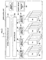
- Fig.1 is a block diagram showing an outline of a configuration of an embodiment of the present invention including a storage system.
- the storage system S comprises a storage control apparatus 101 and HDDs (hard disk drives) 110.
- the storage control apparatus 101 is connected through channels 114 via SAN (storage Area Network) 103 comprising SAN switches to one or plural host computers 102 (two in the drawing).
- SAN storage Area Network
- the storage control apparatus 101 is also connected to a plurality of HDDs 10 for storing data through disk-side channels 111.
- the storage control apparatus 101 comprises a plurality of channel control units (connecting units) 104, a plurality of cache memories (memory units) 113, control information storage areas (memory units) 117, a plurality of disk control units (connecting units) 105, a plurality of FM control units 106, and a matural network 107 inter connecting to the above components via internal paths 115.
- the channel control unit 104 receives an I/O request from the host computer 102 through the channels 114, and interprets the request type of the I/O request such as a REAR/WRITE request for reading or writing data onto a HDD 110 or its object address so as to execute an appropriate process for the request.
- the request type of the I/O request such as a REAR/WRITE request for reading or writing data onto a HDD 110 or its object address so as to execute an appropriate process for the request.
- the cache memory 113 temporarily stores data to be stored on a flash memory 306 (non-volatile storage medium: described later) within the HDD 110 and an FM control unit 106 or data to be sent to the host computer 102.
- the control information storage area 117 is an area for storing control information on the storage system S, which comprises memories such as RAM (Random Access Memory).
- the cache memory 113 and the control information storage area 117 may be separately used by preparing physically different memories depending on the type of information to be stored, or by allocating logically different area thereto.
- the disk control unit 105 provides a control for the HDD 110 through the disk-side channel 111 in response to a request from the channel control unit 104, and performs data acquisition or data storage for which the host computer 102 requests. At this time, the disk control unit 105 may provide control for the HDDs 110 according to RAID (Redundant Arrays of Inexpensive Disk: a scheme for managing a plurality of HDDs), so as to improve reliability, availability and performance of the storage system S.
- RAID Redundant Arrays of Inexpensive Disk: a scheme for managing a plurality of HDDs
- the FM control unit 106 provide control for the flash memory 306 (further details in Fig. 3 ) or for a flash memory device (further details in Figs. 4 and 5 ) within the storage system S.
- the FM control unit 106 acquires or stores data storage requested by the host computer 102 in the flash memory 306 or the flash memory device, in response to the request from the channel control unit 104, etc.
- the FM control unit 106 may provide RAID control for the flash memory device, so as to improve reliability, availability and performance of the storage system S.
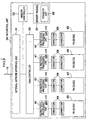
- Fig. 2 is a block diagram showing the configuration of the channel control unit 104.
- the channel control unit 104 comprises a MP (micro processor) unit (processing unit) 220, a plurality of channel protocol processing units 204 and an internal network interface unit 205.
- the MP unit 220 includes a plurality of processors 201, a memory module 202 and a peripheral processing unit 203.
- Each processor 201 is connected to the peripheral processing unit 203 by connection media such as bus.
- the peripheral processing unit 203 is connected to the memory module 202 so as to provide a control for the memory module 202.
- the peripheral processing unit 203 is also connected through a bus 215 of a communication system to the channel protocol processing units 204 and to the internal network interface unit 205.
- the peripheral processing unit 203 receives packets (data) from the processor 201, the channel protocol processing units 204 and the internal network interface unit 205 to which the peripheral processing unit 203 is connected. If a transfer destination address indicated by the received packet is stored on the memory module 202, an appropriate process acceding to the address is performed, and returns the data to the internal network interface unit 205, if necessary.
- the peripheral processing unit 203 performs a data forwarding (data transfer) if the transfer destination address is an address of a location other than the memory module 202.
- the peripheral processing unit 203 is connected to another unit of the storage control apparatus 101 such as the disk control unit 105, via an internal communication network 221 such as LAN (Local Area Network) (further details in Fig. 6 ).
- LAN Local Area Network
- the memory module 202 has a mailbox 213 for communication between the processors 201 connected to the peripheral processing unit 203.
- the processor 201 makes an access to the memory module 202 through the peripheral processing unit 203, and provides an appropriate process in accordance with control programs 212 stored in the memory module 202.
- the memory module 202 stores a transfer list 214 which the channel protocol processing units 204 use when performing DMA (Direct Memory access: a scheme for data transfer not via the processor 201).
- the channel protocol processing unit 204 provides a protocol control over the channels 114, and converts data from the host computer 102 into a protocol format so that it can be processed within the storage system S. Specifically, when receiving an I/O request from the host computer 102 via the channel 114, the channel protocol processing unit 204 notifies the processor 201 of a host computer number, LUN (Logical Unit Number: an identifier for a logical unit of HDD 110, a storage area corresponding to the Logical volume ID 701 in Fig. 7 ) or an access destination address for the I/O request.
- LUN Logical Unit Number: an identifier for a logical unit of HDD 110, a storage area corresponding to the Logical volume ID 701 in Fig. 7
- the processor 201 accesses to directory information on the control information storage area 117 or the directory information which has been copied and expanded on the memory module 202. If there exists an address to which the I/O requested data must be stored or the I/O requested data itself in the directory information, the processor 201 creates the transfer list 214 on the memory module 202. Based on the transfer list 214, the channel protocol processing unit 204 provides a data transfer.
- the processor 201 directs the disk control unit 105 to store the data onto the cache memories 113 (this operation is called as "staging"), and then transfers the data based on the transfer list 214.
- the processor 201 sets the address for the flash memory in the transfer list 214.
- the transfer list 214 is a list for addresses on the cache memories 113 or the flash memories.
- the channel protocol processing unit 204 When receiving a WRITE request from the host computer 102, the channel protocol processing unit 204 writes the data requested from the host computer 102 into a location corresponding to the address in the transfer list 214 through the internal network interface unit 205 via the internal path 115. When receiving a READ request from the host computer 102, the channel protocol processing unit 204 reads the data from the corresponding address appeared in the transfer list 214, and then returns the data to the host computer 102.
- the internal network interface unit 205 serves as an interface for an internal communication between the channel control unit 104 and another storage system S via an internal path 115.
- the disk control unit 105 has approximately the same configuration as that of the 104, the disk control unit 105 has a different part from that corresponding to a control program 212 and a part corresponding to the channel protocol processing units 204 for communicating with the HDD 110.
- the channel 114 and the disk-side channel 111 may have a different protocol from each other.
- the part in the disk control unit 105 corresponding to the channel protocol processing unit 204 is similar to the channel protocol processing unit 204 in the channel control unit 104, with respect of providing a protocol process on the disk-side channel 111 so that the process can be performed within the storage system S.
- the processor 201 If there exists data on the cache memory 113, the processor 201 writes the data on the cache memory 113 into the HDD 110 according to a request from the channel control unit 104 or in a constant time cycle. If there is not data in the cache memory 113, the processor 201 receives a direction from the channel control unit 104, and then reads data from the HDD 110 and writes the data into the cache memories 113, according to this direction.
- the processor 201 accesses to directory information stored on the control information storage area 117 so as to search for a memory address for the cache memory 113 which the data requested from the host computer 102 is to be read out of or to be stored in.
- the disk control unit 105 controls the HDD 110 through the disk-side channel 111. At this time, the disk control unit 105 may provides RAID control for the HDD 110 group so that availability and performance over the entire HDD 110 can be improved.
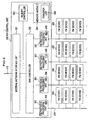
- Fig. 3 is a block diagram showing the configuration of the FM control unit 106.
- the FM control unit 106 comprises an internal network interface unit 301, a DMA controller 302 for providing DMA control, a memory module 304 of a non-volatile memory, a memory controller 303 for controlling the memory module 304, flash memories (FM) 306 as non-volatile storage elements, and memory controllers 305 for controlling the FM 306.
- FM flash memories
- the internal network interface unit 301 serves as an interface for an internal communication between the FM control units 106 and another storage control apparatus 101 via the internal path 115.
- the memory module 304 has a transfer list 308 for performing DMA in the FM control unit 106.
- a DMA controller 302 included in the FM control unit 106 provides a data transfer from the cache memory 113 to the FM 306 according to the transfer list 214 set by the processor 201 of the channel control unit 104, for the sake of creating free capacity in the cache memory 113, for example, when processing the WRITE request from the host computer 102.
- the memory controller 305 provides control for the FM 306 and handles data, in accordance with a READ request from the channel control unit 104 and a WRITE request by the DMA controller 302 via the internal path 115 .
- the memory controller 305 stores information on usage of the FM 306 on the storage area 307 thereof.
- the information stored on the storage area 307 is used for creating a usage status management table 800 (described later in Fig. 8 ).
- ferroelectric memories non-volatile memory using ferroelectric material: FeRAM (Ferroelectric Random Access Memory)
- phase change memories a non-volatile memory for storing data by using change in its amorphous state (i.e. phase change) such as OUM (Ovonic Unified Memory)
- Fig. 4 is a block diagram showing another configuration of the FM control unit 106.
- This FM control unit 106 uses a flash memory (FM) device 409. Descriptions will be omitted on the same configurations by using the same references as in Fig. 3 .
- FM flash memory
- the FM device 409 is a storage system comprising a flash memory or flash memories similar to the FMs 306 in Fig. 3 , a memory controller or controllers 303, and a communication means for communicating with FM protocol processing units 407 (not shown in the drawing).
- the FM device 409 is provided in each FM control unit 106, as show in Fig. 4 , and is detachably connected to the FM control unit 106 via connectors 408. Thus, the replacement of the FM device 409 is facilitated when the device 409 becomes in trouble.
- the processor 201 of the channel control unit 104 may set the transfer list 214 such that a redundant configuration is shared between each FM device 409.
- the above configuration also allows the FM device 409 itself to be replaced with another one having a larger capacity. Communication with the FM device 409 is performed through a general purpose protocol such as FFS (Fast File System). Therefore, the FM protocol processing units 407 converts a format for communication with the FM device 409 to be usable within the storage control apparatus 101.
- FFS Fast File System
- the FM protocol processing unit 407 stores information on the usage of the FM device 409 in a storage area 410, and the information stored on the storage area 410 is used for creating the usage status management table 800 (described later in Fig. 8 ).
- FIG. 5 is a block diagram showing another configuration of the FM control unit 106.
- MF-side channels 510 establish connections to the FM devices 409. Descriptions will be omitted on the same configurations by using the same references as in Fig. 3 or Fig. 4 .
- FM protocol processing units 507 serve similarly as the FM protocol processing units 407 do, and store information on the usage status of the plurality of FM devices 409 connected thereto in its storage area 508.
- the information stored on storage area 508 is used for creating the usage status management table 800 (described later in Fig. 8 ).
- This configuration not only brings the features on the FM control unit 106 described in Fig. 4 , but also allows more FM devices 409 to be connected to the FM control units 106, resulting in realization of a storage system S with a large capacity.
- the FMs 306 in Fig. 3 they may be disposed directly on the substrate.
- the connectors 408, the FM protocol processing units 407 and the FM-side channels 510 can be unnecessary, whereby a more compact storage system S is realized.
- each memory controller 305 can provide a ware leveling adjustment for the FM 306 thereof.
- the memory controller 305 may collect statistic information on the number of erase error occurrences and of bad blocks occurred when accessed to the FM 306, and stores the information on part of the FM 306, or in another FM 306 separately provided, where any means may be provided so as to send this statistic information according to a request from the processor.
- FIG. 6 shows an information flow in an illustrative example of a general configuration in which a plurality of storage control apparatuses 101 are provided. Descriptions will be omitted on the same configurations by using the same references as in Fig. 1 .
- a plurality (two in Fig. 6 ) of storage control apparatuses 101 are connected to a management terminal 601 via a network 602.
- the management terminal 601 may be a common server, serving for collecting internal information from one or plural storage control apparatuses 101,and integrally managing this internal information such as performance and power consumption amount (which may be a conversion value calculated by the number of components in operation based on the basic power consumption amount of each component in the storage control apparatus 101), or statistic information on failure information (further details in Fig. 8 to Fig. 10 )
- the management terminal 601 has a management terminal processing unit (not shown in the drawing) such as CPU (Central Processing Unit) and a management terminal storage unit (not shown in the drawing) such as hard disk drives.
- the management terminal 601 accesses, via a common communication network 602 as a means for collecting information, through the management unit 603 provided in each storage control apparatus 101, to the information stored in the storage control apparatus 101, e.g. the device internal information 604 such as the usage status management table 800 in Fig. 8 stored on the control information storage area 117, or acquires the information 604 through the management unit 603.
- the management terminal 601 creates information 608 (e.g. general information table 1400 in Fig. 14 ) based on the device internal information 604 collected from each storage system 101.
- each channel control unit 104 there exists a MP unit 220 in each channel control unit 104 and a MP 1051 in each disk control unit 105, respectively.
- the management unit 603 can make a direct or indirect access to information collected by each MP unit 220 and 1051, or the device internal information 604 such as configuration information and statistic information which are accumulated in each cache memory 113 or the like.
- the management terminal 601 collates the collected information with predetermined criteria (threshold values), so as to provide an appropriate operation depending on the content of the information. Further description will be given on performances and processes within the management terminal 601, following an explanation on an example of control within the storage control apparatus 101.
- a description will be provided on a device management table for HDD 110 (hereinafter referred to as device as well) (see Fig. 1 if necessary).
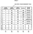
- Fig. 7 shows an example of the device management table 700. Specifically, it explains how to provide management for each storage device (such as control information storage area 117) within the storage control apparatus 101 by using a logical volume management table 700, and management of a logical volume (equivalent to aforementioned Logical Unit) as an example of access objects visible to the host computer 102.
- SAN 103 substituting for SAN 103, it is possible to use another network such as the Internet in use by NAS (Network Attached Storage: a computer dedicated as a file server used in direct connection to a network).
- NAS Network Attached Storage: a computer dedicated as a file server used in direct connection to a network.
- the write access is performed not to a device ID as a physical identifier for the HDD 110, but to a logical volume ID as an identifier for the logical volume.
- a logical volume ID 701 is an identifier for a logical volume, which is associated with a logical device ID 702, an identifier for a logical device of HDD 110 within the storage control apparatus 101.
- the logical device ID 702 is also associated with a virtual device ID 703, that is, an identifier for a virtual device.
- the virtual device ID 703 is associated with a device ID 704 which is an identifier for an actual (physical) device and a device extent 705 indicating a space area within the device.
- the device extent 705 is a management unit for an area where a certain data amount can be stored. According to the embodiment of the present invention, the specific value for the data amount has nothing to do with the essence of the present invention; therefore, this data amount has no limitation.
- the virtual device ID 703 is defined as an aggregate storage area for devices represented by one or a plurality of devices ID 704.
- the logical volume management table 700 is allocated on such a location (e.g. control information storage area 117) where all the processors (MP units 220, 1051) can inquire the management table 700 directly or indirectly.
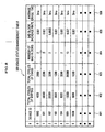
- Fig. 8 shows an example of the usage status management table.
- the usage status management table 800 manages information on property, attribute, usage status for each device associated with its own device ID 801 (corresponding to the device ID 704 in Fig. 7 ). Now, assumed that management is provided for storage media such as flash memories, total cycles of writing 802 and total cycles of erase 803 since the beginning of use, number of bad blocks 804, bad block increase rate 805 and average erase time 806 are associated with the device ID 801. Although not shown in the drawing, each threshold value for the individual information item is managed in the usage status management table 800, or in another table dedicated to management for the threshold values.
- Each of the information and its threshold value are used for the management of the devices. For example, it can be determined that the service life of a device (such as the FM 306) is ending soon when the average erase time 806 of the device becomes longer.
- the usage status management table 800 can also provide management for other devices or storage devices than the FMs 306, to which MAID is applied using ATA (AT Attachment) disk drives or the like, in which cycles of usage (total cycles of writing and total cycles of erase), the number of total spin-up/-down times and error occurrence rate are essential to manage the endurance of the device.
- ATA AT Attachment
- the disk control unit 105 can control the ATA disk drives in its rotation and stop by using the MAID technology.
- the HDD 110 it is not only the HDD 110 alone, but also a disk array device (not shown in the drawing) equipped with HDD 110 and a control unit (s) (not shown in the drawing) that may be connected to the disk control unit 105.
- rotation and stop of the ATA disk drives can be controlled by the instruction of the disk control unit 105 and the MAID equipped to the control unit (not shown in the drawing). That is, the ATA disk drives are vulnerable on a hardware basis; therefore, it is preferable to manage the ATA disk drives in their endurance on the usage status management table 800, as the FM 306 is managed.
- the usage status management table 800 is explained as an example of management for flash memories. However, in the case of ATA disk drives or a device to which the MAID is applied using the ATA disk drives, the usage status management table 800 may include total spin up/down times, total revolution time and error occurrence rate. Specifically, the usage status management table 800 has various information on the endurance of storage media and devices (total usage time, error occurrence rate, bad block increase rate, cycles of access, etc.), depending on the situation.
- the usage status management table 800 is laid out on a location where all the processors (MP units 220, 1051) can inquire the table 800 directly or indirectly as the same case of the logical volume table 700.
- FIG. 9 shows an explanation of a read/write cycle management table 900 (see Fig. 1 if necessary) will be given.
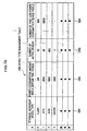
- Fig. 9 shows an example of the read/write cycle management table 900.
- the read/write cycle management table 900 is associated with a logical volume ID 901 (corresponding to the logical volume ID 701), a logical device ID 902 (corresponding to the logical device ID 702), RD cycles (total cycles of reading) 903 and WR cycles (total cycles of writing) 904.
- the read/write cycle management table 900 is updated as statistic information every time an access is made to either of the logical volume ID 901 or the logical device ID 902.
- the read/write cycle management table 900 is allocated at such a location where all the processors (MP units 220, 1051) can inquire the table 900 as the same case of the logical volume management table 700.
- the read/write cycle management table 900 is used in a process in which a large data having more frequencies to be read than those to be written is migrated from the HDD 110 to a flash memory of which power consumption per a certain time period is less than that of a HDD (described later in Fig. 11 to Fig. 13 ) .
- read/write cycle management table 900 data stored on a logical volume which is specified as WORM (Write Once Read Many), read-only, or a long term retention period, may be migrated (from HDD 110 to the FM 306).
- WORM Write Once Read Many
- HDD 110 HDD 110 to the FM 306
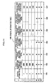
- Fig. 10 shows an example of the device type management table.
- the device type management table 1000 is associated with storage hierarchy device type 1001 indicating a device type, power consumption amount per a certain time period 1002, the number of active devices 1003 indicating the number of devices in operation, and the number of free low power consumption device pools (free capacity of storage media with low power consumption) 1400.
- Flash donates the FMs 306
- ATA donates ATA disk drives which are the entire or part of HDD 110 used in a MAID scheme
- SCSI donates SCSI disk drives which is the entire or part of HDD110.
- Cache donates a RAM in use as cache memories 113.
- the number of free low power consumption device pools 1004 has a unit such as Mega byte (MB) and Giga byte (GB).
- the total amount of power consumption for the storage control apparatus 101 can be obtained in measuring and recording methods by providing a measuring device for actual power consumption (e.g. power meter) at a power source unit (not shown in the drawing) thereof.
- a measuring device for actual power consumption e.g. power meter
- a power source unit not shown in the drawing
- a rough estimate of the total power consumption amount may be calculated by use of the device type management table 1000.
- the storage control apparatus 101 monitors the operation status of each component, the rough estimate of the total power consumption amount can be obtained simply by managing the information in the device type management table 1000 as statistic information.
- the device type management table 1000 can be used such that data is migrated to a lower power consuming device depending on the status of each component and its power consumption amount, so as to reduce the power consumption for each component.
- the device type management table 1000 is laid out at a location where all the processors (MP units 220, 1051) can inquire the table 1000 directly or indirectly as the same case of the logical volume table 700.
- Fig. 11A is a flow chart showing an example of a determination process where the MP unit 220 provides a data migration between HDD 110 and the FM control units 106.
- the timing when the MP unit 220 executes this data migration process is, for example, when receiving periodical READ/WRITE requests from the host computer 102, or when receiving a direction from the host computer 102 to specify a certain logical volume as WORM.
- the MP unit 220 makes a confirmation of collected information (each table in Figs. 8 to 10 ) when executing the determination process for the data migration (S111).
- the MP unit 220 gives an analysis on the status based on the collected information and the determination conditions (n) (S112).
- the determination conditions (n) include, for example, a endurance management for the FM 306 (to determine whether the total cycles of writing exceed the predetermined value or not by inquiring the total cycles of writing 802), reduction in power consumption (to inquire the device type management table 1000), data migration due to a direction of WORM from the host computer 102, RD/WR cycles ratio (by inquiring RD cycles 903 and WR cycles 904, to determine a possibility of data migration to the FM 306 if the RD cycles 903 to the WR cycles 904 ratio exceeds the predetermined value).
- These determination conditions (n) are used in priority in combination with each other.
- the MP unit 220 determines whether a status exceeding the threshold value exists or not, based on the analysis at the step S112 (S113) .
- the step S113 is for determining whether the total cycles of writing of the FM 306 exceeds the threshold value or not, and if it exceeds the threshold value, data thereof is migrated to the HDD 110 having no limitation in cycles of writing.
- the MP unit 220 completes the process.
- the MP unit 220 selects a source and a destination of the data migration (S114), and determine whether a destination of the data migration exists or not, by inquiring the number of free low power consumption device pools 1004, etc. (S115).
- the MP unit 220 determines whether it is possible to generate a data migration destination within the range of a certain condition in a higher priority among the determination conditions or not (S117).
- the MP unit 220 completes the process.
- the MP unit 220 If it is possible to generate the destination of the data migration ("Yes” at S117), the MP unit 220 generates the destination of the data migration (S118), and starts the data migration process (S119).
- part of the data on the FMs 306 may be migrated to the HDD 110 within the range of a certain condition in a higher priority (such as a condition relevant to power consumption) among the determination conditions (n), so as to generate some free capacity for the FMs 306, into which the data can be migrated.
- the MP unit 220 determines whether the status exceeds a certain condition in a higher priority among the determination conditions (n) or not, due to the data migration (S116).
- the MP unit 220 completes the process. For example, although the FMs 306 have no problems in their endurance due to the data migration, the MP unit 202 does not perform the data migration if the condition in a higher priority is not satisfied.
- the MP unit 220 starts a process of the data migration (S119).
- the data migration can be accomplished so as to optimize the total power consumption and the endurance management for the FMs 306 in the storage system S. Specifically, data migration to the FMs 306 with lower power consumption is performed depending on the frequencies of write/read of the device, so that reduction in the total power consumption can be achieved.
- Fig. 11B is a flow chart showing an example of a determination process for performing data migration between the HDD 110 and the FMs 306 by the FM control units 106. Note that this step is performed after the step S119 in Fig. 11A .
- the MP unit 220 determines whether the destination area is in the FMs 306 or not (S1101).
- the MP unit 220 If the destination area is in the FMs 306 ("Yes" at S1101) , a temporary storage area is secured in the HDD 110 since the FMs 306 are sensitive to cycles of writing and performance (S1102). At the same time, the MP unit 220 generates a temporary storage area management table in the control information storage area 117.
- the MP unit 220 creates a management table (not shown in the drawing) for managing the storage area of the data migration destination in a certain unit size (S1103).
- This management table for example, may be a bit map table for managing the data in unit size of 64 KB. Any other tables than the bit map table can be used for this management table, as far as the management can be provided for the progress of the data migration.
- the MP unit 220 sends an direction to the DMA controller 302 to copy the original data to the destination of the data migration (S1104).
- the MP unit 220 checks the area where the data migration is completed in accordance with the above-mentioned management table (i.e. the bit map table), for example, by changing the bit "0" to "1" (S1105).
- the bit map table i.e. the bit map table
- the MP unit 220 determines whether the entire data area of the migration object has been copied according to the management table, that is, whether the progress of the data migration has reached 100% or not (S1106).
- the MP unit 220 repeats the processes at the step S1104 and the step S1105.
- the storage control apparatus 101 occasionally receives READ and WRITE requests for the data during the migration process at the steps S1101 through S1106. An appropriate process in this case will be explained later in Figs. 12 and 13 .
- the MP unit 220 inquires the temporary storage area management table created at the step S1102, and checks whether there exists any data stored on the temporary storage area or not.
- the MP unit 220 reflects the data stored on the temporary storage area on the migration destination area (S1108), and repeats the process at this step S1108 until the migration of the entire data has been completed ("Yes" at S 1109).
- the MP unit 220 proceeds to the step S1110.
- the MP unit 220 rewrites the logical volume management table 700 in accordance with the data migration (S1110). In this case, for example, by changing the ID name in an appropriate cell for the device ID 704 in the table 700 from a migration source device ID to a migration destination device ID, it can be unnecessary to rewrite a virtual device in the host computer (corresponding to the virtual device ID 703).
- the MP unit 220 sets the migration source device free that has become unnecessary at the step S1110, so as to reuse it in other purpose (S1111).
- the data migration can be accomplished in the storage system S, in accordance with the determination result on the migration as described in Fig. 11A .
- Fig. 12 is a flow chart showing an example of the process by the MP unit 220 in this case.
- the MP unit 220 receives a READ request for data during the migration operation from the host computer 102 (S1201), and then makes a confirmation of the latest data storage location (in the migration source device or the temporary storage area) on the management table (created at S 1103 in Fig. 11 ) (S1202).
- the MP unit 220 returns a READ response to the host computer 102, by sending the data from the appropriate storage location thereof (S1203).
- the MP unit 220 copies the migration source data to the migration destination (S1204).
- the MP unit 220 reflects the completion of the operation in the area where data migration has been executed on the management table (S1205).
- the storage system S can meet a READ request from the host computer 102 even while the data migration is being performed.
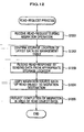
- Fig. 13 is a flow chart showing an example of the process by the MP unit 220 in this case.
- the MP unit 220 receives a WRITE request for data during the migration operation from the host computer 102 (S1301), and then writes the WRITE requested data addressed in correspondence to its access address, into the temporary storage area (S1302).
- the MP unit 220 updates the temporary storage area table which has been created at the step S1102 in Fig. 11B , so as to reflect that the latest data is located in the temporary storage area (S1303).
- the storage system S can meet a WRITE request from the host computer 102 even while the data migration is being performed.
- the data WRITE requested by the host computer 102 is temporarily stored on the temporary storage area, and then reflected later, so that a smooth data migration operation can be accomplished even if the migration destination is such a device as the FMs 306 in which a write is carried out by a complicated procedure such as adding, replacement of pointer and block erase, or as a device using ATA disk drives for dealing only a disk device requiring for repeated spin-up and -downs.
- Fig. 14 shows an example of a general information table 1400 for use in the case that the management terminal 601 described in Fig. 6 provides a power consumption management for the entire storage systems S.
- a control device ID 1401 as an identifier for the storage control apparatus 101, power consumption amount 1402 per a certain time period in each storage control apparatus 101, active devices 1403 indicating the number of low power consumption media in operation such as the FMs 306, total capacity of active devices 1404 indicating the total capacity of low power consumption media in operation, active devices 1405 indicating the number of normal power consumption media such as HDD 110, total capacity of active devices 1406 indicating the total capacity of normal power consumption media in operation, and free low power consumption device pools 1407 indicating the number of free low power consumption devices are associated respectively.
- this general information table 1400 enables the data to be migrated from the normal power consumption device to a low power consumption device within another storage control apparatus 101, whereby reduction in power consumption can be achieved over the entire storage systems S.
- threshold values for power consumption over the entire storage systems S are stored and managed in the general information table 1400 or in different tables dedicated to the management for the threshold values (not shown in the drawing) .
- the specific processes of the data migration are similar to those according to the flow charts in Figs. 11A to 13 .
- the data migration process between devices within the same single storage control apparatus 101 shown in Fig. 11B may be executed between devices in different storage control apparatuses 101.
- the host computer 102 may be allowed to recognize changes of the access destination devices. Or it could be accomplished by the volume virtualization software on the host computer 102 or the virtualization switch to recognize the changes of the access destination devices.
- the storage system S can realize a system with low power consumption, no deterioration in performance on required data, configurable in a large scale, and capable of storing data into optimum storage media.
- the storage system S can also improve reliability and availability over the system with respect to properties (such as endurance of rewriting cycles and fault tolerance) that each storage medium has.
Landscapes
- Engineering & Computer Science (AREA)
- Theoretical Computer Science (AREA)
- Human Computer Interaction (AREA)
- Physics & Mathematics (AREA)
- General Engineering & Computer Science (AREA)
- General Physics & Mathematics (AREA)
- Information Retrieval, Db Structures And Fs Structures Therefor (AREA)
- Memory System Of A Hierarchy Structure (AREA)
- Techniques For Improving Reliability Of Storages (AREA)
Claims (22)
- Dispositif de commande de mémorisation (101) comportant :une pluralité d'unités de connexion (104) connectées à un ou plusieurs ordinateurs hôtes (102) et à une ou plusieurs unités de disque dur (110) en tant que supports de mémorisation pour mémoriser des données,un ou plusieurs supports de mémorisation non-volatile (306) qui sont d'un type différent de support de mémorisation par rapport à celui des unités de disque dur (110) et qui mémorisent des données ECRIRE demandées par l'ordinateur hôte (102),une pluralité d'unités de traitement (220) pour traiter des demandes ECRIRE et LIRE en provenance de l'ordinateur hôte (102) en utilisant les unités de disque dur (110) ou le support de mémorisation non-volatile (306),une pluralité d'unités de traitement de protocole de canal (204),une pluralité d'unités de mémoire (117) pour mémoriser des informations de commande à utiliser par les unités de traitement,une mémoire cache (113) pour mémoriser temporairement des données à envoyer à l'ordinateur hôte (102) depuis lesdites unités de disque dur (110), etun réseau (107) pour interconnecter les composants ci-dessus du dispositif de commande de mémorisation,dans lequel,les unités de disque dur (110) sont fournies sous forme d'une unité séparée ou d'une partie d'un dispositif de réseau de disques ayant des unités de commande (105),les informations de commande mémorisées dans chaque unité de mémoire (117) sont un tableau de gestion d'états d'utilisation (800) qui associe un identifiant pour chaque support de mémorisation à des informations sur un état d'utilisation de chaque support de mémorisation,chaque unité de mémoire (117) est en outre adaptée pour mémoriser une valeur de seuil pour les informations sur l'état d'utilisation de chaque support de mémorisation,chaque unité de traitement (220) est adaptée pour interroger le tableau de gestion d'états d'utilisation (800) et chaque valeur de seuil, les deux sont mémorisés dans chaque unité de mémoire (117), et est adaptée pour migrer des données mémorisées dans l'un des supports de mémorisation de l'un ou l'autre type dont l'état d'utilisation dépasse la valeur de seuil pour l'état d'utilisation vers l'un des supports de mémorisation de l'autre type si l'une quelconque des informations sur l'état d'utilisation dépasse la valeur de seuil de celui-ci, etl'unité de traitement de protocole de canal (204) a une liste de transferts (214) qui inclut l'adresse de la mémoire cache (113) ou du support de mémorisation non-volatile (306), lors de la réception d'une demande de lecture en provenance de l'ordinateur hôte, l'unité de traitement de protocole de canal (204) lit des données à partir de la mémoire cache ou du support de mémorisation non-volatile sur la base d'une adresse correspondante apparaissant dans la liste de transferts.
- Dispositif de commande de mémorisation (101) selon la revendication 1, dans lequel chaque support de mémorisation non-volatile (306) comporte une mémoire flash.
- Dispositif de commande de mémorisation (101) selon la revendication 1, dans lequel chaque support de mémorisation non-volatile (306) comporte une mémoire ferroélectrique.
- Dispositif de commande de mémorisation (101) selon la revendication 1, dans lequel chaque support de mémorisation non-volatile (306) comporte une mémoire à changement de phase.
- Dispositif de commande de mémorisation (101) selon l'une quelconque des revendications 1 à 4, dans lequel chaque unité de traitement (220) est adaptée pour mettre en rotation ou arrêter l'unité de disque dur (110) en utilisant un schéma MAID (Massive Array of Idle Disks) directement ou via les unités de commande (105) du dispositif du réseau de disques.
- Dispositif de commande de mémorisation (101) selon la revendication 5, dans lequel l'unité de disque dur (110) comporte au moins soit une unité de disque SCSI (interface pour petits systèmes informatiques) soit une unité de disque ATA (AT Attachment).
- Dispositif de commande de mémorisation (101) selon l'une quelconque des revendications 1 à 6, dans lequel,
chaque support de mémorisation non-volatile (306) à moins de cycles réinscriptibles que l'unité de disque dur (110),
le tableau de gestion d'états d'utilisation (800) inclut des cycles de réécriture (802) en tant qu'informations sur l'état d'utilisation pour chaque support de mémorisation,
chaque unité de mémoire (117) mémorise une valeur de seuil pour les cycles de réécriture en tant que valeur de seuil, et
chaque unité de traitement (220) interroge le tableau de gestion d'états d'utilisation (800) et la valeur de seuil pour les cycles de réécriture, les deux sont mémorisés dans chaque unité de mémoire (117), et migre des données mémorisées dans l'un des supports de mémorisation de l'un ou l'autre type dont les cycles de réécriture dépassent la valeur de seuil pour les cycles de réécriture vers l'un des supports de mémorisation de l'autre type si l'une quelconque des informations sur les cycles de réécriture dépasse la valeur de seuil de celui-ci. - Dispositif de commande de mémorisation (101) selon l'une quelconque des revendications 1 à 7, dans lequel,
l'unité de disque dur (110) a une vitesse de réponse de lecture/écriture inférieure à celle de chaque support de mémorisation non-volatile (306),
le tableau de gestion d'états d'utilisation (800) inclut des cycles d'utilisation d'écriture de données (802) ou de lecture de données (803) en tant qu'informations sur l'état d'utilisation de chaque support de mémorisation,
chaque unité de mémoire (117) mémorise une valeur de seuil pour les cycles d'utilisation d'écriture de données ou de lecture de données en tant que valeur de seuil, et
chaque unité de traitement (220) est adaptée pour interroger le tableau de gestion d'états d'utilisation (800) et la valeur de seuil pour les cycles d'utilisation d'écriture de données (802) ou de lecture de données (803), les deux sont mémorisés dans chaque unité de mémoire (117), et est adaptée pour migrer des données mémorisées dans l'un des supports de mémorisation de l'un ou l'autre type dont les cycles d'utilisation d'écriture de données ou de lecture de données dépassent la valeur de seuil pour les cycles d'utilisation d'écriture de données ou de lecture de données vers l'un des supports de mémorisation de l'autre type si l'une quelconque des informations sur les cycles d'utilisation d'écriture de données ou de lecture de données dépasse la valeur de seuil de celui-ci. - Dispositif de commande de mémorisation (101) selon l'une quelconque des revendications 1 à 8, dans lequel,
le tableau de gestion d'états d'utilisation (800) inclut le nombre de zones défaillantes (804) en tant qu'informations sur l'état d'utilisation de chaque support de mémorisation,
chaque unité de mémoire (117) mémorise une valeur de seuil pour le nombre de zones défaillantes en tant que valeur de seuil, et
chaque unité de traitement (220) est adaptée pour interroger le tableau de gestion d'états d'utilisation (800) et la valeur de seuil pour le nombre de zones défaillantes, les deux sont mémorisés dans chaque unité de mémoire (117), et est adaptée pour migrer des données mémorisées dans l'un des supports de mémorisation de l'un ou l'autre type dont le nombre de zones défaillantes dépasse la valeur de seuil pour le nombre de zones défaillantes vers l'un des supports de mémorisation de l'autre type si l'une quelconque des informations sur le nombre de zones défaillantes dépasse la valeur de seuil de celui-ci. - Dispositif de commande de mémorisation (101) selon l'une quelconque des revendications 1 à 9,
dans lequel,
si le support de mémorisation de l'autre type qui est une destination de migration de données est l'un des supports de mémorisation non-volatile (306), chaque unité de traitement (220) est adaptée pour sécuriser une zone particulière sur l'unité de disque dur (110) en tant que zone de mémorisation temporaire, et
lors de la réception d'une demande LIRE pour une partie des données en provenance de l'ordinateur hôte (102) pendant l'opération de migration de données, l'unité de traitement (220) est adaptée pour renvoyer des données correspondantes mémorisées dans le support de mémorisation de la source de migration de données vers l'ordinateur hôte, et traite de manière asynchrone la migration de données partie par partie, tour à tour, dans le support de mémorisation de la destination de migration de données. - Dispositif de commande de mémorisation (101) selon l'une quelconque des revendications 1 à 9,
dans lequel,
si le support de mémorisation de l'autre type qui est une destination de migration de données est l'un des supports de mémorisation non-volatile (306), chaque unité de traitement (220) sécurise une zone particulière sur l'unité de disque dur en tant que zone e mémorisation temporaire, et
lorsque l'unité de traitement (220) reçoit une demande LIRE pour une partie des données en provenance de l'ordinateur hôte (102) pendant l'opération de migration de données, et si de nouvelles données correspondant à la partie des données sont déjà mémorisées dans l'un des supports de mémorisation non-volatile par l'intermédiaire d'une autre demande ECRIRE provenant de l'ordinateur hôte, l'unité de traitement renvoie les nouvelles données vers l'ordinateur hôte. - Dispositif de commande de mémorisation (101) selon l'une quelconque des revendications 1 à 9,
dans lequel,
si le support de mémorisation de l'autre type qui est une destination de migration de données est l'un des supports de mémorisation non-volatile (306), chaque unité de traitement (220) est adaptée pour sécuriser une zone particulière sur l'unité de disque dur (110) en tant que zone de mémorisation temporaire, et
lorsque l'unité de traitement (220) reçoit une demande ECRIRE pour une partie des données en provenance de l'ordinateur hôte (102), l'unité de traitement est adaptée pour mémoriser de nouvelles données correspondant à la partie des données mémorisées dans la zone temporaire sur la zone de mémorisation temporaire, et l'unité de traitement est adaptée pour copier les nouvelles données sur le support de mémorisation non-volatile (306) une fois la migration des données terminée. - Dispositif de commande de mémorisation (101) selon l'une quelconque des revendications 1 à 12,
dans lequel,
le tableau de gestion d'états d'utilisation (800) inclut le nombre d'erreurs d'opération d'effacement en tant qu'informations sur l'état d'utilisation pour chaque support de mémorisation,
chaque unité de mémoire (117) mémorise une valeur de seuil pour le nombre d'erreurs d'opération d'effacement en tant que valeur de seuil, et
chaque unité de traitement (220) est adaptée pour interroger le tableau de gestion d'états d'utilisation (800) et la valeur de seuil pour le nombre d'erreurs d'opération d'effacement, les deux sont mémorisés dans chaque unité de mémoire (117), et migrer des données mémorisées dans l'un des supports de mémorisation de l'un ou l'autre type dont le nombre d'erreurs d'opération d'effacement dépasse la valeur de seuil pour le nombre d'erreurs d'opération d'effacement vers l'un des supports de mémorisation de l'autre type si l'une quelconque des informations sur le nombre d'erreurs d'opération dépasse la valeur de seuil de celui-ci. - Dispositif de commande de mémorisation (101) selon l'une quelconque des revendications 1 à 13,
dans lequel,
le tableau de gestion d'états d'utilisation (800) inclut une durée d'effacement moyenne (806) en tant qu'informations sur l'état d'utilisation pour chaque support de mémorisation,
chaque unité de mémoire (117) mémorise une valeur de seuil pour la durée d'effacement moyenne en tant que valeur de seuil, et
chaque unité de traitement (220) est adaptée pour interroger le tableau de gestion d'états d'utilisation (800) et la valeur de seuil pour les durées d'effacement moyennes, les deux sont mémorisés dans chaque unité de mémoire (117), et migrer des données mémorisées dans l'un des supports de mémorisation de l'un ou l'autre type dont la durée d'effacement moyenne dépasse la valeur de seuil pour la durée d'effacement moyenne vers l'un des supports de mémorisation de l'autre type si l'une quelconque des informations sur la durée d'effacement moyenne dépasse la valeur de seuil de celui-ci. - Système de gestion de données comportant :des dispositifs de commande de mémorisation (101) selon la revendication 1, etau moins un terminal de gestion (601) connecté aux dispositifs de commande de mémorisation (101),dans lequel,le terminal de gestion (601) a une unité de traitement de terminal de gestion et une unité de mémorisation de terminal de gestion,l'unité de mémorisation de terminal de gestion est adaptée pour mémoriser un tableau d'informations générales (1400) incluant une quantité de consommation d'énergie par période de temps particulière (1402) pour chaque dispositif de commande de mémorisation et une valeur de seuil pour une quantité de consommation d'énergie totale pour une période de temps particulière des dispositifs de commande de mémorisation (101), etl'unité de traitement de terminal de gestion est adaptée pour interroger le tableau d'informations générales (1400) et calculer la quantité de consommation d'énergie totale pour une période de temps particulière des dispositifs de commande de mémorisation (101), et si la quantité de consommation d'énergie calculée dépasse la valeur de seuil pour la consommation d'énergie totale pour une période de temps particulière sur les dispositifs de commande de mémorisation entiers, une migration de données est effectuée entre les supports de mémorisation dans le dispositif de commande de mémorisation, ou entre les supports de mémorisation parmi les dispositifs de commande de mémorisation de manière à réduire la consommation d'énergie pour une période de temps particulière.
- Système de gestion de données selon la revendication 15, dans lequel le tableau d'informations générales (1400) inclut une zone libre du support de mémorisation ayant une consommation d'énergie inférieure (1407) dans chaque dispositif de commande de mémorisation (101).
- Procédé de gestion de données mis en oeuvre par au moins un dispositif de commande de mémorisation (101), le dispositif comportant : une pluralité d'unités de connexion (104) connectées à un ou plusieurs ordinateurs hôtes (102) et à une ou plusieurs unités de disque dur (110) en tant que supports de mémorisation pour mémoriser des données, un ou plusieurs supports de mémorisation non-volatile (306) qui sont d'un type différent par rapport aux unités de disque dur et qui mémorisent des données ECRIRE demandées par l'ordinateur hôte, une pluralité d'unités de traitement (220) pour traiter des demandes ECRIRE et LIRE en provenance de l'ordinateur hôte en utilisant l'unité de disque dur ou le support de mémorisation non-volatile, une pluralité d'unités de traitement de protocole de canal (204), une pluralité d'unités de mémoire (117) pour mémoriser des informations de commande à utiliser par les unités de traitement, une mémoire cache (113) pour mémoriser temporairement des données à envoyer à l'ordinateur hôte depuis lesdites unités de disque dur (110), et un réseau (107) pour interconnecter les composants ci-dessus du dispositif de commande de mémorisation,
le procédé comportant les étapes consistant à :mémoriser dans chaque unité de mémoire (117) les informations qui sont un tableau de gestion d'états d'utilisation (800) associant chaque identifiant pour chaque support de mémorisation à des informations sur l'état d'utilisation de chaque support de mémorisation,mémoriser en outre dans chaque unité de mémoire (117) chaque valeur de seuil pour les informations sur l'état d'utilisation de chaque support de mémorisation,interroger sur chaque unité de traitement (220) le tableau d'états d'utilisation et chaque valeur de seuil, les deux sont mémorisés dans l'unité de mémoire (117), et migrer des données (S119) mémorisées dans l'un des supports de mémorisation de l'un ou l'autre type dont l'état d'utilisation dépasse la valeur de seuil pour l'état d'utilisation vers l'un des supports de mémorisation de l'autre type si l'une quelconque des informations sur l'état d'utilisation de chaque support de mémorisation dépasse la valeur de seuil de celui-ci (S113), etlors de la réception d'une demande de lecture en provenance de l'ordinateur hôte (102), l'unité de traitement de protocole de canal (204) lit des données à partir de la mémoire cache (113) ou du support de mémorisation non-volatile (306) sur la base de l'adresse correspondante apparaissant dans une liste de transferts (214) dans l'unité de traitement qui inclut l'adresse de la mémoire cache du support de mémorisation non-volatile. - Procédé de gestion de données selon la revendication 17, dans lequel la gestion de données est effectuée en utilisant chaque support de mémorisation non-volatile (306) qui est une mémoire flash.
- Procédé de gestion de données selon la revendication 17 ou la revendication 18, dans lequel la gestion de données est effectuée en utilisant :chaque support de mémorisation non-volatile (306) ayant moins de cycles réinscriptibles que l'unité de disque dur (110),le tableau de gestion d'états d'utilisation (800) incluant des cycles de réécriture (802) en tant qu'informations sur l'état d'utilisation de chaque support de mémorisation,chaque unité de mémoire (117) mémorisant une valeur de seuil pour les cycles de réécriture en tant que valeur de seuil, etchaque unité de traitement (220) interrogeant le tableau de gestion d'états d'utilisation (800) et la valeur de seuil pour les cycles de réécriture, les deux sont mémorisés dans chaque unité de mémoire (117), et migrant des données mémorisées dans l'un des supports de mémorisation non-volatile (306) qui dépasse la valeur de seuil pour les cycles de réécriture vers l'une des unités de disque dur (110).
- Procédé de gestion de données selon l'une quelconque des revendications 17 à 19, dans lequel la gestion de données est effectuée en utilisant :chaque unité de disque dur (110) ayant une vitesse de réponse de lecture/écriture plus lente que celle de chaque support de mémorisation non-volatile (306),le tableau de gestion d'états d'utilisation (800) incluant des cycles d'utilisation de lecture/écriture (802, 803) en tant qu'informations pour l'état d'utilisation pour chaque support de mémorisation,chaque unité de mémoire (117) mémorisant une valeur de seuil pour les cycles d'utilisation de lecture/écriture en tant que valeur de seuil, etchaque unité de traitement (220) interrogeant le tableau de gestion d'états d'utilisation (800) et la valeur de seuil, les deux sont mémorisés dans chaque unité de mémoire (117), et migrant des données mémorisées dans l'un des supports de mémorisation de l'un ou l'autre type dont les cycles d'utilisation de lecture/écriture dépassent la valeur de seuil pour les cycles d'utilisation de lecture/écriture vers l'un des supports de mémorisation de l'autre type si l'une quelconque des informations sur les cycles d'utilisation de lecture/écriture de chaque support de mémorisation dépasse la valeur de seuil de celui-ci.
- Dispositif de commande de mémorisation (101) selon la revendication 1, dans lequel, si le support de mémorisation de l'autre type qui est une destination de migration de données est l'un des supports de mémorisation non-volatile (306), chaque unité de traitement (220) sécurise une zone particulière sur l'unité de disque dur (110) en tant que zone de mémorisation temporaire.
- Procédé de gestion de données selon la revendication 17, dans lequel, si le support de mémorisation de l'autre type qui est une destination de migration de données est l'un des supports de mémorisation non-volatile (306), chaque unité de traitement (220) sécurise une zone particulière sur l'unité de disque dur (110) en tant que zone de mémorisation temporaire.
Applications Claiming Priority (1)
| Application Number | Priority Date | Filing Date | Title |
|---|---|---|---|
| JP2005275018 | 2005-09-22 |
Publications (2)
| Publication Number | Publication Date |
|---|---|
| EP1768014A1 EP1768014A1 (fr) | 2007-03-28 |
| EP1768014B1 true EP1768014B1 (fr) | 2008-07-16 |
Family
ID=36888016
Family Applications (1)
| Application Number | Title | Priority Date | Filing Date |
|---|---|---|---|
| EP06250922A Expired - Lifetime EP1768014B1 (fr) | 2005-09-22 | 2006-02-21 | Appareil de contrôle de stockage, système de gestion de données et procédé de gestion de données |
Country Status (4)
| Country | Link |
|---|---|
| US (1) | US7568075B2 (fr) |
| EP (1) | EP1768014B1 (fr) |
| CN (3) | CN101676857B (fr) |
| DE (1) | DE602006001812D1 (fr) |
Families Citing this family (79)
| Publication number | Priority date | Publication date | Assignee | Title |
|---|---|---|---|---|
| JP4933861B2 (ja) * | 2005-09-22 | 2012-05-16 | 株式会社日立製作所 | ストレージ制御装置、データ管理システムおよびデータ管理方法 |
| JP4740796B2 (ja) * | 2006-05-29 | 2011-08-03 | パナソニック株式会社 | 画像記録再生装置 |
| JP4749255B2 (ja) * | 2006-07-03 | 2011-08-17 | 株式会社日立製作所 | 複数種類の記憶デバイスを備えたストレージシステムの制御装置 |
| GB0614515D0 (en) | 2006-07-21 | 2006-08-30 | Ibm | An apparatus for managing power-consumption |
| KR20080017982A (ko) * | 2006-08-23 | 2008-02-27 | 삼성전자주식회사 | 플래시 메모리 시스템 및 그 프로그램 방법 |
| KR100845527B1 (ko) * | 2006-12-06 | 2008-07-10 | 삼성전자주식회사 | 메모리 장치 및 메모리 컨트롤러의 클럭 싸이클 제어방법 |
| US20080168193A1 (en) * | 2007-01-10 | 2008-07-10 | International Business Machines Corporation | Use of unique identifiers for each data format supported by a multi-format data store |
| US8166315B1 (en) * | 2007-03-23 | 2012-04-24 | Emc Corporation | Method for calculating power for data storage systems |
| JP5149556B2 (ja) * | 2007-07-30 | 2013-02-20 | 株式会社日立製作所 | システム情報要素を移行するストレージシステム |
| TWI372397B (en) * | 2007-08-06 | 2012-09-11 | Ind Tech Res Inst | Method and system of defect management for storage medium |
| EP2195724B1 (fr) | 2007-08-28 | 2019-10-09 | Commvault Systems, Inc. | Gestion d'énergie de ressources de traitement de données, telle que la gestion adaptative d'énergie d'opérations de stockage de données |
| JP5124217B2 (ja) * | 2007-09-18 | 2013-01-23 | 株式会社日立製作所 | ストレージ装置 |
| US7984313B2 (en) * | 2008-04-17 | 2011-07-19 | International Business Machines Corporation | Method, apparatus and system for reducing power consumption involving data storage devices |
| US8291245B2 (en) * | 2008-04-17 | 2012-10-16 | International Business Machines Corporation | Method, apparatus and system for reducing power consumption based on storage device data migration |
| US20090271564A1 (en) * | 2008-04-25 | 2009-10-29 | Hitachi, Ltd. | Storage system |
| US8285919B2 (en) * | 2008-05-27 | 2012-10-09 | Initio Corporation | SSD with improved bad block management |
| US8135907B2 (en) * | 2008-06-30 | 2012-03-13 | Oracle America, Inc. | Method and system for managing wear-level aware file systems |
| CN101625642B (zh) * | 2008-07-07 | 2012-06-06 | 李锦峰 | 磁盘管理系统及其管理方法 |
| KR101466585B1 (ko) * | 2008-07-10 | 2014-11-28 | 삼성전자주식회사 | 메모리 장치 및 메모리 장치의 관리 방법 |
| CN101625901A (zh) | 2008-07-10 | 2010-01-13 | 深圳市朗科科技股份有限公司 | 半导体存储介质的寿命预警方法、系统及装置 |
| WO2010038258A1 (fr) * | 2008-10-01 | 2010-04-08 | Hitachi, Ltd. | Système de stockage avec fonction d’exécution de formatage ou de broyage |
| CN101729272B (zh) * | 2008-10-27 | 2013-01-23 | 华为技术有限公司 | 内容分发方法、系统、设备及媒体服务器 |
| US8301852B2 (en) * | 2008-11-13 | 2012-10-30 | International Business Machines Corporation | Virtual storage migration technique to minimize spinning disks |
| CN101406980B (zh) * | 2008-11-21 | 2011-04-27 | 北京工业大学 | 一种电弧长度控制方法 |
| US20100153474A1 (en) * | 2008-12-16 | 2010-06-17 | Sandisk Il Ltd. | Discardable files |
| US8205060B2 (en) * | 2008-12-16 | 2012-06-19 | Sandisk Il Ltd. | Discardable files |
| US8849856B2 (en) * | 2008-12-16 | 2014-09-30 | Sandisk Il Ltd. | Discardable files |
| US9015209B2 (en) | 2008-12-16 | 2015-04-21 | Sandisk Il Ltd. | Download management of discardable files |
| US9020993B2 (en) | 2008-12-16 | 2015-04-28 | Sandisk Il Ltd. | Download management of discardable files |
| US8375192B2 (en) * | 2008-12-16 | 2013-02-12 | Sandisk Il Ltd. | Discardable files |
| US9104686B2 (en) | 2008-12-16 | 2015-08-11 | Sandisk Technologies Inc. | System and method for host management of discardable objects |
| US20100235473A1 (en) * | 2009-03-10 | 2010-09-16 | Sandisk Il Ltd. | System and method of embedding second content in first content |
| EP2411914A1 (fr) * | 2009-03-24 | 2012-02-01 | Hitachi, Ltd. | Appareil d'enregistrement et son procédé de commande de données |
| US8285681B2 (en) | 2009-06-30 | 2012-10-09 | Commvault Systems, Inc. | Data object store and server for a cloud storage environment, including data deduplication and data management across multiple cloud storage sites |
| DE112010003577T5 (de) * | 2009-09-08 | 2012-06-21 | International Business Machines Corp. | Datenverwaltung in Halbleiterspeicher-Einheiten und mehrstufigen Speichersystemen |
| TWI483258B (zh) * | 2010-02-26 | 2015-05-01 | Transcend Information Inc | 使用壞區塊增加率的記憶體異常警示方法以及相關的儲存裝置預警系統 |
| US9396104B1 (en) * | 2010-03-22 | 2016-07-19 | Seagate Technology, Llc | Accessing compressed data of varying-sized quanta in non-volatile memory |
| US8549229B2 (en) | 2010-08-19 | 2013-10-01 | Sandisk Il Ltd. | Systems and methods for managing an upload of files in a shared cache storage system |
| US8463802B2 (en) | 2010-08-19 | 2013-06-11 | Sandisk Il Ltd. | Card-based management of discardable files |
| GB2485706A (en) * | 2010-09-07 | 2012-05-23 | Ibm | Data management in solid-state storage devices and tiered storage systems |
| CN102147711B (zh) * | 2010-12-31 | 2014-04-02 | 华为数字技术(成都)有限公司 | 一种基于数据内容识别的存储方法及装置 |
| US8788849B2 (en) | 2011-02-28 | 2014-07-22 | Sandisk Technologies Inc. | Method and apparatus for protecting cached streams |
| JP5971509B2 (ja) * | 2011-08-30 | 2016-08-17 | ソニー株式会社 | 情報処理装置および方法、並びに記録媒体 |
| US9223790B1 (en) * | 2011-08-31 | 2015-12-29 | Amazon Technologies, Inc. | Managing deletion of data in a data storage system |
| JP2013061847A (ja) * | 2011-09-14 | 2013-04-04 | Sony Corp | 情報処理装置および情報処理方法 |
| EP2791775A1 (fr) * | 2012-03-13 | 2014-10-22 | Hitachi, Ltd. | Système de stockage ayant un dispositif de stockage permanent à semi-conducteurs avec une mémoire permanente à semi-conducteurs |
| US9262496B2 (en) | 2012-03-30 | 2016-02-16 | Commvault Systems, Inc. | Unified access to personal data |
| US8950009B2 (en) | 2012-03-30 | 2015-02-03 | Commvault Systems, Inc. | Information management of data associated with multiple cloud services |
| JP5820078B2 (ja) * | 2012-09-07 | 2015-11-24 | 株式会社日立製作所 | 記憶装置システム |
| JP6126493B2 (ja) * | 2012-09-27 | 2017-05-10 | パナソニック インテレクチュアル プロパティ コーポレーション オブ アメリカPanasonic Intellectual Property Corporation of America | サーバ装置、端末装置、保守整備情報送信方法およびコンピュータプログラム |
| US10346259B2 (en) | 2012-12-28 | 2019-07-09 | Commvault Systems, Inc. | Data recovery using a cloud-based remote data recovery center |
| JP5825290B2 (ja) * | 2013-04-08 | 2015-12-02 | コニカミノルタ株式会社 | 画像形成装置 |
| JP6084685B2 (ja) * | 2013-04-26 | 2017-02-22 | 株式会社日立製作所 | ストレージシステム |
| CN104956312B (zh) * | 2013-12-12 | 2018-02-13 | 株式会社日立制作所 | 存储装置及存储装置的控制方法 |
| CN103914264B (zh) * | 2014-03-12 | 2017-09-12 | 汉柏科技有限公司 | 一种矩阵硬盘的数据存储方法及系统 |
| WO2015161443A1 (fr) | 2014-04-22 | 2015-10-29 | 华为技术有限公司 | Procédé de gestion de fichiers et système de fichiers |
| US9671960B2 (en) * | 2014-09-12 | 2017-06-06 | Netapp, Inc. | Rate matching technique for balancing segment cleaning and I/O workload |
| CN104281536B (zh) * | 2014-09-28 | 2019-03-01 | 株洲南车时代电气股份有限公司 | 一种数据分离储存的装置以及方法 |
| WO2016082227A1 (fr) * | 2014-11-29 | 2016-06-02 | 华为技术有限公司 | Procédé et appareil de stockage de données |
| CN106293635B (zh) * | 2015-05-13 | 2018-10-30 | 华为技术有限公司 | 指令块处理方法及装置 |
| KR102401600B1 (ko) | 2015-08-31 | 2022-05-25 | 삼성전자주식회사 | 데이터 양에 기초하여 복수의 데이터 스트림을 관리하도록 구성되는 스토리지 장치 |
| CN105573923A (zh) * | 2015-12-11 | 2016-05-11 | 中国航空工业集团公司西安航空计算技术研究所 | 一种访问多块存储空间的控制电路 |
| US11108858B2 (en) | 2017-03-28 | 2021-08-31 | Commvault Systems, Inc. | Archiving mail servers via a simple mail transfer protocol (SMTP) server |
| US11074138B2 (en) | 2017-03-29 | 2021-07-27 | Commvault Systems, Inc. | Multi-streaming backup operations for mailboxes |
| US10552294B2 (en) | 2017-03-31 | 2020-02-04 | Commvault Systems, Inc. | Management of internet of things devices |
| US11294786B2 (en) | 2017-03-31 | 2022-04-05 | Commvault Systems, Inc. | Management of internet of things devices |
| US11221939B2 (en) | 2017-03-31 | 2022-01-11 | Commvault Systems, Inc. | Managing data from internet of things devices in a vehicle |
| KR102430209B1 (ko) * | 2017-09-07 | 2022-08-05 | 삼성전자주식회사 | 저장 장치 및 저장 장치에 포함된 컨트롤러들 |
| CN108345510B (zh) * | 2018-01-11 | 2022-02-08 | 中国人民解放军国防科技大学 | 一种自动巡检检测大规模离线归档系统可靠性的方法 |
| US11106391B2 (en) * | 2018-04-25 | 2021-08-31 | Micron Technology, Inc. | Managing a memory system including memory devices with different characteristics |
| CN109101437A (zh) * | 2018-07-20 | 2018-12-28 | 浪潮电子信息产业股份有限公司 | 一种数据存储方法与终端 |
| US10891198B2 (en) | 2018-07-30 | 2021-01-12 | Commvault Systems, Inc. | Storing data to cloud libraries in cloud native formats |
| JP6978087B2 (ja) * | 2019-03-26 | 2021-12-08 | Necプラットフォームズ株式会社 | ストレージ制御装置、制御方法及びプログラム |
| CN110929796B (zh) * | 2019-11-28 | 2023-04-07 | 重庆长安汽车股份有限公司 | 基于多源传感器决策层数据融合方法、系统及存储介质 |
| JP7145902B2 (ja) * | 2020-03-04 | 2022-10-03 | 株式会社日立製作所 | ストレージシステム及びその制御方法 |
| CN115298652A (zh) * | 2020-04-30 | 2022-11-04 | 北京嘀嘀无限科技发展有限公司 | 用于存储介质健康评估的系统和方法 |
| US11604706B2 (en) | 2021-02-02 | 2023-03-14 | Commvault Systems, Inc. | Back up and restore related data on different cloud storage tiers |
| US11921655B2 (en) * | 2021-05-04 | 2024-03-05 | Stmicroelectronics, Inc. | Dynamic memory protection device system and method |
| TWI790165B (zh) * | 2022-05-06 | 2023-01-11 | 力晶積成電子製造股份有限公司 | 改善nor型快閃記憶體耐受力的方法 |
Family Cites Families (19)
| Publication number | Priority date | Publication date | Assignee | Title |
|---|---|---|---|---|
| US5778418A (en) * | 1991-09-27 | 1998-07-07 | Sandisk Corporation | Mass computer storage system having both solid state and rotating disk types of memory |
| US6347051B2 (en) * | 1991-11-26 | 2002-02-12 | Hitachi, Ltd. | Storage device employing a flash memory |
| US6549974B2 (en) * | 1992-06-22 | 2003-04-15 | Hitachi, Ltd. | Semiconductor storage apparatus including a controller for sending first and second write commands to different nonvolatile memories in a parallel or time overlapped manner |
| US5619453A (en) * | 1995-07-28 | 1997-04-08 | Micron Quantum Devices, Inc. | Memory system having programmable flow control register |
| JP2000057039A (ja) * | 1998-08-03 | 2000-02-25 | Canon Inc | アクセス制御方法及び装置及びファイルシステム及び情報処理装置 |
| US6314503B1 (en) * | 1998-12-30 | 2001-11-06 | Emc Corporation | Method and apparatus for managing the placement of data in a storage system to achieve increased system performance |
| US6330621B1 (en) | 1999-01-15 | 2001-12-11 | Storage Technology Corporation | Intelligent data storage manager |
| CN1222876C (zh) * | 1999-09-22 | 2005-10-12 | 网孔公司 | 磁盘冗余阵列控制器和使其与主机连接的方法 |
| US20050204187A1 (en) * | 2004-03-11 | 2005-09-15 | Lee Charles C. | System and method for managing blocks in flash memory |
| JP4031190B2 (ja) * | 2000-09-29 | 2008-01-09 | 株式会社東芝 | メモリカード、不揮発性メモリ、不揮発性メモリのデータ書き込み方法及びデータ書き込み装置 |
| KR100644602B1 (ko) * | 2000-10-11 | 2006-11-10 | 삼성전자주식회사 | 플래시메모리를 위한 재사상 제어방법 및 그에 따른플래시 메모리의 구조 |
| TWI240864B (en) * | 2001-06-13 | 2005-10-01 | Hitachi Ltd | Memory device |
| US7028158B1 (en) * | 2001-11-02 | 2006-04-11 | Beatty And Company Computing, Inc. | Storage virtualization engine |
| US7035972B2 (en) * | 2002-09-03 | 2006-04-25 | Copan Systems, Inc. | Method and apparatus for power-efficient high-capacity scalable storage system |
| JP4110000B2 (ja) * | 2003-01-28 | 2008-07-02 | 株式会社ルネサステクノロジ | 記憶装置 |
| JP4428993B2 (ja) * | 2003-11-27 | 2010-03-10 | 株式会社日立製作所 | ディスクアレイ装置及びディスクアレイ装置の制御方法 |
| JP4485230B2 (ja) * | 2004-03-23 | 2010-06-16 | 株式会社日立製作所 | マイグレーション実行方法 |
| US7269708B2 (en) * | 2004-04-20 | 2007-09-11 | Rambus Inc. | Memory controller for non-homogenous memory system |
| US7426605B2 (en) * | 2005-09-30 | 2008-09-16 | Rudelic John C | Method and apparatus for optimizing flash device erase distribution |
-
2005
- 2005-10-26 US US11/258,282 patent/US7568075B2/en not_active Expired - Fee Related
-
2006
- 2006-02-21 EP EP06250922A patent/EP1768014B1/fr not_active Expired - Lifetime
- 2006-02-21 DE DE602006001812T patent/DE602006001812D1/de not_active Expired - Lifetime
- 2006-06-29 CN CN2009102047482A patent/CN101676857B/zh not_active Expired - Fee Related
- 2006-06-29 CN CNB2006100943114A patent/CN100565441C/zh not_active Expired - Fee Related
- 2006-09-22 CN CNB2006101393041A patent/CN100485586C/zh not_active Expired - Fee Related
Also Published As
| Publication number | Publication date |
|---|---|
| CN100485586C (zh) | 2009-05-06 |
| CN100565441C (zh) | 2009-12-02 |
| DE602006001812D1 (de) | 2008-08-28 |
| CN101676857B (zh) | 2013-04-24 |
| US20070067559A1 (en) | 2007-03-22 |
| CN1936818A (zh) | 2007-03-28 |
| US7568075B2 (en) | 2009-07-28 |
| CN101676857A (zh) | 2010-03-24 |
| CN1959598A (zh) | 2007-05-09 |
| EP1768014A1 (fr) | 2007-03-28 |
Similar Documents
| Publication | Publication Date | Title |
|---|---|---|
| EP1768014B1 (fr) | Appareil de contrôle de stockage, système de gestion de données et procédé de gestion de données | |
| US8166270B2 (en) | Storage control apparatus, data management system and data management method for determining storage heirarchy based on a user policy | |
| US8214586B2 (en) | Apparatus and method for mirroring data between nonvolatile memory and a hard disk drive | |
| US9495105B2 (en) | System managing a plurality of flash memory devices | |
| JP4819369B2 (ja) | ストレージシステム | |
| US7822928B2 (en) | Storage device and storage device data life cycle control method | |
| US7814351B2 (en) | Power management in a storage array | |
| US20080276016A1 (en) | Storage controller and storage controller control method | |
| US20130151762A1 (en) | Storage device | |
| US8627126B2 (en) | Optimized power savings in a storage virtualization system | |
| de Assunção et al. | State of the art on technology and practices for improving the energy efficiency of data storage | |
| de Assunçaoa et al. | State of the Art on Technology and Practices for Improving the Energy Efficiency of Data Storage |
Legal Events
| Date | Code | Title | Description |
|---|---|---|---|
| PUAI | Public reference made under article 153(3) epc to a published international application that has entered the european phase |
Free format text: ORIGINAL CODE: 0009012 |
|
| 17P | Request for examination filed |
Effective date: 20060310 |
|
| AK | Designated contracting states |
Kind code of ref document: A1 Designated state(s): AT BE BG CH CY CZ DE DK EE ES FI FR GB GR HU IE IS IT LI LT LU LV MC NL PL PT RO SE SI SK TR |
|
| AX | Request for extension of the european patent |
Extension state: AL BA HR MK YU |
|
| 17Q | First examination report despatched |
Effective date: 20070405 |
|
| AKX | Designation fees paid |
Designated state(s): DE FR GB IE |
|
| GRAP | Despatch of communication of intention to grant a patent |
Free format text: ORIGINAL CODE: EPIDOSNIGR1 |
|
| GRAS | Grant fee paid |
Free format text: ORIGINAL CODE: EPIDOSNIGR3 |
|
| GRAA | (expected) grant |
Free format text: ORIGINAL CODE: 0009210 |
|
| AK | Designated contracting states |
Kind code of ref document: B1 Designated state(s): DE FR GB IE |
|
| REG | Reference to a national code |
Ref country code: GB Ref legal event code: FG4D |
|
| REF | Corresponds to: |
Ref document number: 602006001812 Country of ref document: DE Date of ref document: 20080828 Kind code of ref document: P |
|
| REG | Reference to a national code |
Ref country code: IE Ref legal event code: FG4D |
|
| PGFP | Annual fee paid to national office [announced via postgrant information from national office to epo] |
Ref country code: IE Payment date: 20090108 Year of fee payment: 4 |
|
| PLBE | No opposition filed within time limit |
Free format text: ORIGINAL CODE: 0009261 |
|
| STAA | Information on the status of an ep patent application or granted ep patent |
Free format text: STATUS: NO OPPOSITION FILED WITHIN TIME LIMIT |
|
| 26N | No opposition filed |
Effective date: 20090417 |
|
| PGFP | Annual fee paid to national office [announced via postgrant information from national office to epo] |
Ref country code: FR Payment date: 20090128 Year of fee payment: 4 |
|
| REG | Reference to a national code |
Ref country code: FR Ref legal event code: ST Effective date: 20101029 |
|
| PG25 | Lapsed in a contracting state [announced via postgrant information from national office to epo] |
Ref country code: IE Free format text: LAPSE BECAUSE OF NON-PAYMENT OF DUE FEES Effective date: 20100222 Ref country code: FR Free format text: LAPSE BECAUSE OF NON-PAYMENT OF DUE FEES Effective date: 20100301 |
|
| PGFP | Annual fee paid to national office [announced via postgrant information from national office to epo] |
Ref country code: DE Payment date: 20170214 Year of fee payment: 12 |
|
| PGFP | Annual fee paid to national office [announced via postgrant information from national office to epo] |
Ref country code: GB Payment date: 20170215 Year of fee payment: 12 |
|
| REG | Reference to a national code |
Ref country code: DE Ref legal event code: R119 Ref document number: 602006001812 Country of ref document: DE |
|
| GBPC | Gb: european patent ceased through non-payment of renewal fee |
Effective date: 20180221 |
|
| PG25 | Lapsed in a contracting state [announced via postgrant information from national office to epo] |
Ref country code: DE Free format text: LAPSE BECAUSE OF NON-PAYMENT OF DUE FEES Effective date: 20180901 |
|
| PG25 | Lapsed in a contracting state [announced via postgrant information from national office to epo] |
Ref country code: GB Free format text: LAPSE BECAUSE OF NON-PAYMENT OF DUE FEES Effective date: 20180221 |