EP1768068A2 - Verfahren und Anordnung zur Bestimmung der dreidimensionalen Darstellung eines tubulären Organs - Google Patents
Verfahren und Anordnung zur Bestimmung der dreidimensionalen Darstellung eines tubulären Organs Download PDFInfo
- Publication number
- EP1768068A2 EP1768068A2 EP06120587A EP06120587A EP1768068A2 EP 1768068 A2 EP1768068 A2 EP 1768068A2 EP 06120587 A EP06120587 A EP 06120587A EP 06120587 A EP06120587 A EP 06120587A EP 1768068 A2 EP1768068 A2 EP 1768068A2
- Authority
- EP
- European Patent Office
- Prior art keywords
- dimensional
- mps
- dimensional image
- image
- organ
- Prior art date
- Legal status (The legal status is an assumption and is not a legal conclusion. Google has not performed a legal analysis and makes no representation as to the accuracy of the status listed.)
- Granted
Links
Images


Classifications
-
- A—HUMAN NECESSITIES
- A61—MEDICAL OR VETERINARY SCIENCE; HYGIENE
- A61B—DIAGNOSIS; SURGERY; IDENTIFICATION
- A61B5/00—Measuring for diagnostic purposes; Identification of persons
- A61B5/103—Measuring devices for testing the shape, pattern, colour, size or movement of the body or parts thereof, for diagnostic purposes
- A61B5/107—Measuring physical dimensions, e.g. size of the entire body or parts thereof
- A61B5/1076—Measuring physical dimensions, e.g. size of the entire body or parts thereof for measuring dimensions inside body cavities, e.g. using catheters
-
- A—HUMAN NECESSITIES
- A61—MEDICAL OR VETERINARY SCIENCE; HYGIENE
- A61B—DIAGNOSIS; SURGERY; IDENTIFICATION
- A61B5/00—Measuring for diagnostic purposes; Identification of persons
- A61B5/06—Devices, other than using radiation, for detecting or locating foreign bodies ; Determining position of diagnostic devices within or on the body of the patient
-
- A—HUMAN NECESSITIES
- A61—MEDICAL OR VETERINARY SCIENCE; HYGIENE
- A61B—DIAGNOSIS; SURGERY; IDENTIFICATION
- A61B8/00—Diagnosis using ultrasonic, sonic or infrasonic waves
- A61B8/08—Clinical applications
- A61B8/0833—Clinical applications involving detecting or locating foreign bodies or organic structures
- A61B8/0841—Clinical applications involving detecting or locating foreign bodies or organic structures for locating instruments
-
- A—HUMAN NECESSITIES
- A61—MEDICAL OR VETERINARY SCIENCE; HYGIENE
- A61B—DIAGNOSIS; SURGERY; IDENTIFICATION
- A61B8/00—Diagnosis using ultrasonic, sonic or infrasonic waves
- A61B8/12—Diagnosis using ultrasonic, sonic or infrasonic waves in body cavities or body tracts, e.g. by using catheters
-
- A—HUMAN NECESSITIES
- A61—MEDICAL OR VETERINARY SCIENCE; HYGIENE
- A61B—DIAGNOSIS; SURGERY; IDENTIFICATION
- A61B8/00—Diagnosis using ultrasonic, sonic or infrasonic waves
- A61B8/42—Details of probe positioning or probe attachment to the patient
- A61B8/4245—Details of probe positioning or probe attachment to the patient involving determining the position of the probe, e.g. with respect to an external reference frame or to the patient
- A61B8/4254—Details of probe positioning or probe attachment to the patient involving determining the position of the probe, e.g. with respect to an external reference frame or to the patient using sensors mounted on the probe
-
- A—HUMAN NECESSITIES
- A61—MEDICAL OR VETERINARY SCIENCE; HYGIENE
- A61B—DIAGNOSIS; SURGERY; IDENTIFICATION
- A61B8/00—Diagnosis using ultrasonic, sonic or infrasonic waves
- A61B8/46—Ultrasonic, sonic or infrasonic diagnostic devices with special arrangements for interfacing with the operator or the patient
- A61B8/461—Displaying means of special interest
- A61B8/463—Displaying means of special interest characterised by displaying multiple images or images and diagnostic data on one display
-
- A—HUMAN NECESSITIES
- A61—MEDICAL OR VETERINARY SCIENCE; HYGIENE
- A61B—DIAGNOSIS; SURGERY; IDENTIFICATION
- A61B8/00—Diagnosis using ultrasonic, sonic or infrasonic waves
- A61B8/48—Diagnostic techniques
- A61B8/483—Diagnostic techniques involving the acquisition of a 3D volume of data
-
- A—HUMAN NECESSITIES
- A61—MEDICAL OR VETERINARY SCIENCE; HYGIENE
- A61B—DIAGNOSIS; SURGERY; IDENTIFICATION
- A61B8/00—Diagnosis using ultrasonic, sonic or infrasonic waves
- A61B8/52—Devices using data or image processing specially adapted for diagnosis using ultrasonic, sonic or infrasonic waves
- A61B8/5215—Devices using data or image processing specially adapted for diagnosis using ultrasonic, sonic or infrasonic waves involving processing of medical diagnostic data
- A61B8/5238—Devices using data or image processing specially adapted for diagnosis using ultrasonic, sonic or infrasonic waves involving processing of medical diagnostic data for combining image data of patient, e.g. merging several images from different acquisition modes into one image
-
- G—PHYSICS
- G06—COMPUTING OR CALCULATING; COUNTING
- G06T—IMAGE DATA PROCESSING OR GENERATION, IN GENERAL
- G06T7/00—Image analysis
-
- G—PHYSICS
- G06—COMPUTING OR CALCULATING; COUNTING
- G06T—IMAGE DATA PROCESSING OR GENERATION, IN GENERAL
- G06T7/00—Image analysis
- G06T7/50—Depth or shape recovery
- G06T7/55—Depth or shape recovery from multiple images
-
- A—HUMAN NECESSITIES
- A61—MEDICAL OR VETERINARY SCIENCE; HYGIENE
- A61B—DIAGNOSIS; SURGERY; IDENTIFICATION
- A61B6/00—Apparatus or devices for radiation diagnosis; Apparatus or devices for radiation diagnosis combined with radiation therapy equipment
- A61B6/12—Arrangements for detecting or locating foreign bodies
-
- G—PHYSICS
- G06—COMPUTING OR CALCULATING; COUNTING
- G06T—IMAGE DATA PROCESSING OR GENERATION, IN GENERAL
- G06T2207/00—Indexing scheme for image analysis or image enhancement
- G06T2207/30—Subject of image; Context of image processing
- G06T2207/30004—Biomedical image processing
- G06T2207/30101—Blood vessel; Artery; Vein; Vascular
Definitions
- the disclosed technique relates to organ assessment, in general, and to methods and systems for determining a 3D representation of a tubular organ, in particular.
- 3D visual representation of an organ assists a physician in assessing the condition of that organ. More particularly, a 3D representation of a tubular organ, such as a coronary vessel, helps identify and assess plaque burden and lesion dimensions such as length, diameter and volume. Further more, a 3D representation of a tubular organ aids the physician to identify, on a 2D image, regions of foreshortening of the vessel caused by the projection of the 3D vessel on a 2D plane. Additionally, with the aid of the 3D representation of the tubular organ, a physician can identify bifurcation points of that tubular organ.
- U.S. patent 6,169,917 entitled “Method and Device for Reconstructing Three-Dimensional Images of Blood Vessels, Particularly coronary vessel, or Other Three-Dimensional Structure” to Masotti et al, directs to a method wherein three X-Ray images, from three different perspective are provided.
- a reference object comprising two planes, integral with the patient, containing at least six points with known three-dimensional coordinates, opaque to the image radiation, provides the perspective transformations associated with each angiographic image. Using these transformations, and a set of points of projection of a three-dimensional object, the three-dimensional object is reconstructed.
- the reconstruction is determined using a semi-automatic algorithm. Initially, a starting point and an initial direction of the vessel are determined. From thereon, the next segment of the vessel, whose length is proportional to the actual radius thereof, is identified. The segment is identified according to the probability that the vessel proceeds in a given direction. This probability is determined by calculating the mean gray level contained in a rectangular mask which is rotated about the point belonging to the center line of the vessel.
- U.S. patent 6,148,095 entitled “Apparatus and Method for Determining Three-Dimensional Representation of Tortuous Vessel” to Prause et al directs to an apparatus and method for reconstruction of the coronary vessel, generated from ECG-gated intravascular ultrasound (IVUS) frames obtained by a catheter, combined with biplane angiography. Initially, the IVUS catheter is positioned at the distal end-point of the designated vessel. The IVUS catheter is withdrawn at a fixed speed while biplane X-ray images are acquired. The IVUS catheter obtains ultrasound images from within the vessel during the withdrawal.
- IVUS intravascular ultrasound
- a 3D representation of the centerline of the vessel can be reconstructed.
- Using this 3D centerline representation in conjunction with information about the physical properties of the catheter a 3D pullback path of the catheter is determined.
- the IVUS images are then mapped to the determined 3D pullback path according to the pullback speed and catheter twist.
- the gaps between adjacent IVUS slice are filled by interpolation.
- the IVUS images are further correlated with the activity phase of the heart.
- the activity phase of the heart is obtained by Electrocardiogram (ECG), to ensure that the images are obtained under consistent conditions.
- ECG Electrocardiogram
- the rotation matrix and translation vector representing the relative orientation of the images are determined.
- the correspondence between the 2D centerlines, corresponding to each image is established and a 3D vessel centerline is calculated.
- a 3D visual representation, of the target object is reconstructed based on the 3D vessel centerline and diameter of each vessel, estimated along the 3D centerline of each vessel. Consequently, the optimal views, of the vessel segments, with minimal vessel foreshortening, are determined.
- U.S. Patent 6,456,271 entitled “Vascular Reconstruction” to Reidfeld directs to a method and apparatus for reconstructing blood vessels in three dimensions.
- a catheter including a position sensor, is advanced into the blood vessel and the position of the sensor is acquired at a plurality of points in the vessel. Based on these points, a centerline and the inner surface of the blood vessel are calculated. The plurality of points is fitted to a parametric representation of the vessel centerline. Each coordinate dimension, in the parametric representation, is represented by a polynomial.
- the inner surface of the blood vessel is reconstructed about the centerline by generating a tube of either fixed or variable radius.
- This tube is generated by determining plurality of unit vectors, sampling the circle around the centerline, and multiplying these unit vectors by the radius of the tube.
- the radius is determined by averaging the distances of the points from the centerline.
- a reconstruction, with variable radius, is achieved by averaging the distances of a plurality of points in a vicinity of interest. Alternatively, the radius may be selected by the user. Using the centerline and the radius a wire frame of the blood vessel is generated and the rectangular patches composing the wire frame are shaded.
- a method for determining a three dimensional representation of a tubular organ comprising the procedures of registering a three dimensional medical positioning system (MPS) coordinate system with a two dimensional coordinate system.
- MPS three dimensional medical positioning system
- the MPS points are associated with the MPS coordinated system, each of the MPS point is acquired with a respective organ timing signal reading.
- Acquiring at least one two dimensional image of the tubular organ, the at least one two dimensional image is associated with the two dimensional coordinate system, the at least one two dimensional image is acquired from at least one perspective angle, each of the at least one two dimensional image is further acquired with a respective organ timing signal reading.
- a system for determining a three dimensional representation of a tubular organ comprising an organ timing signal detector, a medical imaging system, a medical positioning system (MPS), a catheter fitted with an MPS sensor, and a processor.
- the medical imaging system is associated with a two dimensional coordinate system.
- the MPS is associated with a three dimensional MPS coordinate system.
- the processor is coupled with the MPS, with the organ timing signal detector and with the medical imaging system.
- the MPS is coupled with the organ timing signal detector and with the MPS sensor fitted on the catheter.
- the processor is coupled with the MPS, the organ timing signal detector and with the medical imaging system.
- the organ timing signal detector acquires an organ timing signal reading representing the activity state of the organ.
- Medical imaging system acquires at least one two dimensional image from at least one perspective.
- the at least one least one two dimensional image is associated with a respective organ timing signal reading.
- the catheter is inserted into the tubular organ and the MPS acquires a plurality of MPS points.
- Each of the MPS points is associated with a respective organ timing signal reading.
- the processor registers the three dimensional MPS coordinate system with the two dimensional coordinate system, associates an organ timing signal reading with each of the MPS points and with each of the at least one two dimensional image and determines a three dimensional representation of the tubular organ.
- the disclosed technique overcomes the disadvantages of the prior art, by providing a method and a system for determining a 3D representation of a tubular organ.
- a plurality of Medical Positioning System (MPS) points representing the positions of an MPS sensor, within the tubular organ, are acquired.
- the MPS sensor is fitted on a catheter and is associated with a 3D MPS coordinate system.
- This catheter may be a Guided Measurement Catheter (GMC), a diagnostic catheter (e.g., Ultra Sound imaging catheter) or a therapeutic catheter (e.g., stenting catheter or an ablating catheter).
- GMC Guided Measurement Catheter
- diagnostic catheter e.g., Ultra Sound imaging catheter
- a therapeutic catheter e.g., stenting catheter or an ablating catheter.
- a contrast dye is injected into the tubular organ and at least one 2D image (e.g., X-ray image, magnetic resonance image, positron emission tomography image or ultrasound image), from at least one perspective angle, of that tubular organ, is acquired.
- the 2D image is associated with a 2D coordinate system.
- the contrast dye highlights the tubular organ in the image.
- the 2D coordinate system is registered with the 3D MPS coordinate system (e.g., by an optical-magnetic calibration procedure). After the MPS points are acquired, a 3D representation of the tubular organ is determined and displayed.
- the MPS points represent the 3D trajectory of the MPS sensor within the tubular organ. This 3D trajectory is projected on the 2D image, thereby defining the centerline of the tubular organ on that 2D image.
- the 2D borders of the tubular organ, identifiable on the 2D image, are detected according to the defined centerline, by an image segmentation process.
- a 3D circle is generated around each MPS point, the diameter of the 3D circle being the distance between the detected borders at the respective MPS point. This 3D circle defines the 3D border of the 3D representation of the tubular organ.
- the resulting 3D representation of the tubular organ is limited to a circular cross section.
- the tubular organ might have an oval cross section or other arbitrary cross sections. Therefore, a plurality of 2D images, from different perspective angles of the tubular organ, are acquired. The contour of the 3D border is refined according to the detected 2D border points of the tubular organ on each 2D image, and the resulting cross section is a closed curve.
- the inspected tubular organ may move. This motion affects the MPS sensor readings (e.g., position and orientation). Therefore, while acquiring MPS point readings and 2D images, the system simultaneously acquires organ timing signals of organs (e.g., the heart, the lungs). These organ timing signals represent the activity state of the organs. Accordingly, each of the MPS points and each 2D image are associated with a respective organ timing signal reading. Consequently, each MPS point is associated with a respective 2D image according to the organ timing signals thereof.
- a unique 3D trajectory, of the MPS sensor is defined for each activity state and therefore for each 2D image. This unique 3D trajectory is projected on the respective 2D image when the centerline of the tubular organ is defined as described above.
- System 100 includes medical imaging system 118 associated with a 2D coordinate system, a Medical Positioning System (MPS) 124 associated with a 3D MPS coordinate system, an organ timing signal detector 126, a processor 128, a catheter 106, a display unit 122 and a table 104.
- Medical imaging system 118 includes an imaging radiation transmitter 120 and an imaging radiation detector 116.
- Medical positioning system 124 includes MPS transmitters 110, 112 and 114, reference sensor 130 and an MPS sensor (not shown).
- Processor 128 is coupled with organ timing signal detector 126, with imaging radiation detector 116, with MPS 124 and with Display unit 122.
- MPS 124 is coupled with organ timing signal detector 126 and with catheter 106.
- the MPS sensors (not shown) are coupled with distal end 108 of catheter 106.
- MPS transmitters 110, 112 and 114 are coupled with imaging radiation detector 116.
- Catheter 106 is inserted into tubular organ 134 and MPS 124 acquires a plurality of MPS points within tubular organ 134.
- Medical imaging system 118 acquires at least one 2D image of tubular organ 134 from at least one perspective.
- the 2D images are provided to processor 128.
- Processor 128 registers the 3D MPS coordinate system with the 2D coordinate system and projects the 3D trajectory of the catheter on each of the 2D images.
- the centerline of the tubular organ on the respective 2D image is defined.
- processor 128 detects the 2D borders of a portion of organ 134 identifiable on the respective 2D image.
- processor 128 determines a 3D representation of a portion of the tubular organ.
- Display 122 displays 3D representation 132 of organ 134.
- Display 122 may further display 3D representation 132 of organ 134 superimposed on a 2D image.
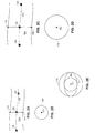
- FIGS 2A, 2B, 2C, 2D, 2E and 2F are schematic illustrations of exemplary two 2D images of tubular organ 150 acquired from two different perspective angles and the resulting cross section and 3D representation of tubular organ 150 in accordance with another embodiment of the disclosed technique.
- the inspected tubular organ is assumed stationary.
- Both 2D images include centerline 152 which is defined by projection of the 3D trajectory of a catheter. The 3D trajectory is determined by MPS points 154, 156 and 158.
- border points 160 and 162 ( Figure 2A) and border points 166 and 168 ( Figure 2C) of tubular organ 150 are detected. These detected border points are used to define the constraints of the closed curve that will define the 3D borders of tubular organ 150. In this exemplary case, these constraints are the distance between border points 160 and 162 ( Figure 2A), and the distance between border points 166 and 168 ( Figure 2C). These distances define diameters of circles. Using these defined diameters, a circle is generated around each MPS point. In Figure 2B, the diameter of circle 164 corresponds to the distance between border points 160 and 162 (Figure 2A) at MPS point 156 ( Figure 2A) as detected from the first perspective.
- the diameter of circle 170 corresponds to the distance between the border points 166 and 168 (Figure 2C) at MPS point 156 ( Figure 2C) as detected from the second perspective.
- a contour 172 (Figure 2E) is traced from circle 160 and 162.
- Contour 172 has the shape of an ellipse since it is generated from two circles.
- a 3D model such as 3D model 132 ( Figure 2F and Figure 1) is determined.
- the inspected organ may move during the acquisition of the MPS points and the 2D image or images. More particularly, when the tubular organ is a coronary artery, the tubular organ is involved in a cyclic motion according to the cardiac cycle, caused by the pressurized flow of blood therein. Therefore, the MPS points are associated with the 2D images (e.g., by synchronization), according to the organ timing signals acquired simultaneously therewith.
- FIGS. 3A and 3B are a schematic illustration of three 2D images, of tubular organ in the body of a patient, acquired at three different activity states of the organ, and the MPS points acquired during these three different activity states, in accordance with a further embodiment of the disclosed technique.
- the first image of the organ, designated 180 1 was acquired at a first activity state T 1 .
- the second image of the organ, designated 180 2 was acquired at a second activity state T 2 .
- the third image of the organ, designated 180 3 was acquired at a third activity state T 3 .
- MPS points 182, 188 and 194 were acquired.
- MPS points 184, 190 and 198 were acquired.
- centerline 200 is the projection of the catheter 3D trajectory on image 180 1 .
- Centerline 202 is the projection of the catheter 3D trajectory on image 180 2 .
- Centerline 204 is the projection of the catheter 3D trajectory on image 180 3 .
- the borders such as borders 206 and 208 are detected.
- a circle is generated around each MPS point, using the distance between these borders, at a particular MPS point, as the diameter of the respective circle.
- Catheter 106 is inserted into tubular organ 134 and MPS 124 acquires a plurality of MPS points within organ 134.
- Medical imaging system 118 acquires at least one 2D image of tubular organ 134 from at least one perspective.
- organ timing signal detector 126 detects the activity state of the organ.
- each MPS point and each 2D image is associated with an organ timing signal reading.
- Organ timing signal detector 126 detects the organ timing signal from the acquired MPS points, by filtering periodic motions of the MPS sensor (not shown) relative to reference sensor 130. Detecting organ timing signals from MPS points is further described in U.S. patent application 10/986567 , which is incorporated herein by reference.
- organ timing signal detector 126 is an Electrocardiogram (ECG) detector fitted with body surface electrodes.
- ECG Electrocardiogram
- each of medical imaging system 118 and MPS 124 has a different organ timing signal detector.
- Processor 128 registers the 3D MPS coordinate system with the 2D coordinate system.
- Processor 128 associates each MPS point with the corresponding 2D image according to the detected organ timing signals.
- Figure 4 is a schematic illustration of a method for determining a 3D representation of a tubular organ in accordance with a further embodiment of the disclosed technique.
- a 3D MPS coordinate is registered with a 2D coordinate system. Consequently every point in the 3D MPS coordinate system is mapped to a point in the 2D coordinate system.
- processor 128 registers the 3D MPS coordinate system with the 2D coordinate system.
- a plurality of MPS points, within a tubular organ, with a respective organ time signal reading for each MPS point are acquired.
- the MPS points are acquired with a catheter, fitted with an MPS sensor, into the tubular organ.
- the MPS points are acquired during the insertion of the catheter or during a manual or automatic pullback of the catheter.
- the organ timing signal associated with each MPS point reading represents the activity state of the organ during the acquisition of the MPS point.
- MPS 124 acquires a plurality of MPS points, within organ 134, with an MPS sensor coupled with distal end 108 of catheter 106.
- the organ timing signals are detected by organ timing signal detector 126.
- procedure 224 at least one 2D image of a tubular organ is acquired form at least one angle perspective angles of the organ, with a respective organ timing signal reading for each image.
- a dye Prior to the acquisition of the at least one 2D image, a dye is injected into the tubular organ. This dye may be injected by the catheter acquiring the MPS points.
- medical imaging system 118 acquires at least one 2D image of tubular organ 134 from at least one perspective.
- the organ timing signals are detected by organ timing signal detector 126. After procedures 220 and 222 the method proceeds to procedure 224.
- each of the MPS points is associated with the 2D images, according to the organ timing signals thereof.
- each MPS point is associated with a respective 2D image.
- processor 128 associates each of the MPS points with a respective 2D image detected by imaging radiation detector 116.
- a temporal 3D representation of a portion of the tubular organ is determined for each MPS point, with the MPS point and from the borders of the tubular organ, identifiable in the respective 2D image. Determining the 3D representation is further explained in conjunction with Figure 5.
- Processor 128 determines a 3D representation of a portion of the tubular organ, for each MPS point, from the MPS point and from the 2D border of the tubular organ, identifiable in the respective 2D image.
- 3D representation 132 is displayed on display 132.
- the determined 3D representation is superimposed on a 2D image.
- the 3D representation may be projected on any of the at least one 2D images.
- the 3D representation may further be projected on a real time 2D image. Therefore, the system selects a desired angle of perspective of the real time 2D and projects the 3D representation on that real time 2D image.
- the 2D projection of the 3D representation can function as a virtual dye. Therefore, there is no need to inject a dye into the tubular organ prior to the acquisition of the real time 2D image.
- the disclosed technique further enables to identify bifurcation points of the tubular organ. Virtual dye and bifurcation points are further illustrated in conjunction with Figure 6. It is noted that bifurcation points can be identified on the 3D representation.
- processor 128 projects the determined 2D representation on one of the 2D images and displays it on display 122.
- Figure 5 is a method for determining a 3D model of a tubular organ in accordance with another embodiment of the disclosed technique.
- procedure 250 at least one 2D image is selected, the image includes the tubular organ.
- processor 128 selects one or more 2D images.
- procedure 252 the 3D trajectory of the catheter, determined by the associated MPS points, is projected on each selected 2D image. Thereby, a centerline of the tubular organ is defined.
- processor 128 projects the 3D trajectory of the catheter on the selected 2D image, thereby, defining the centerline of the tubular organ.
- the 2D border points of the tubular organ, on the selected image are detected. These 2D border points are detected using the defined centerline and image processing techniques. These image processing techniques may be for example edge detection. With reference to Figure 1, processor 128 detects the borders of the tubular organ on the selected image.
- a 3D closed curve is generated around each MPS point, associated with each selected image.
- the detected 2D border points, at each MPS point determines the constraints of that closed curve (e.g., the circumference of the closed curve must included these border points).
- the closed curve is a circle.
- the diameter of that circle is the distance between the detected 2D borders of the tubular organ.
- the refined contour will have the shape of an ellipse.
- the shape of the closed curve is arbitrary.
- processor 128 generates a 3D closed curve around each MPS point associated with the selected image.
- FIG. 6 is a schematic illustration of image 280 of a tubular organ in accordance with a further embodiment of the disclosed technique.
- 2D projection 282of a 3D representation of the tubular organ is superimposed on image 280.
- 2D projection 282 serves as a virtual dye of the tubular organ.
- point 284 is identified as a bifurcation point.
- a bifurcation point is determined when after identifying only two borders for one MPS point, now for the next MPS point, the system identifies at least three borders, with a gap between two adjacent ones. The bifurcation point resides in the transition area between these two MPS points. The system then verifies that this is indeed a bifurcation point with the aid of another 2D image, from another perspective angle of the tubular organ.
- the inspected tubular organ may be infected with lesions or plaque. Consequently, the determined borders may be those of the lesion within the tubular organ and not the actual borders of the tubular organ.
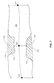
- FIG 7 is a schematic illustration of a tubular organ 300 infected by lesions 302 and 304 in accordance with another embodiment of the disclosed technique.
- borders 312 and 314 were determined as the borders of tubular organ 300.
- borders 312 and 314 do not represent the true borders of tubular organ 300.
- the physician selects MPS points 306 and 310 as reference points for the true width of tubular organ 300.
- True borders 316 and 318 are determined (e.g., by interpolation) according to the width between borders 312 and 314 at MPS points 306 and 310. Furthermore, using true borders and the lesion borders, characteristics, such as the position, the length and the volume of the lesion can be determined. When, for example, a procedure of placing a stent device in an artery is performed, a mark, representing the location of the lesion may be superimposed on a real time image of the artery. Consequently, the physician can accurately navigate the stenting catheter to the location of the lesion.
- the true dimensions of the object may be distorted.
- a sphere will appear as a circle if projected onto a 2D image plane.
- the object is a tubular organ within the human body, such as a coronary artery, that tubular organ may curve "into" or "out of” the image plane.
- the true length of the tubular organ may be distorted. This phenomenon is called foreshortening. Since the 3D representation of the tubular organ was constructed from a 3D trajectory of a catheter, within the tubular organ, the system provides the physician with information regarding the true length of the displayed tubular organ. Furthermore, the system provides the physician with a representation of the true length of the tubular organ on the 2D image.
- FIG 8 is a schematic illustration of a 2D image generally reference 330 of tubular organ 332 in accordance with a further embodiment of the disclosed technique.
- 3D trajectory 334 of tubular organ 332 is projected on 2D image 330.
- a plurality of equally spaced markers points 336 are marked on 3D trajectory 334.
- the space between each pair of marker points 336 on 3D trajectory 334 is a tangible unit of length (e.g., 1 millimeter).
- 3D trajectory 334 and marker points 336 are projected on 2D image 330. Consequently, where the foreshortening phenomenon worsens, the distance between adjacent pairs of marker points 336, on the plane of 2D image 330, is observed to decrease.
- the physician has both a quantitative assessment of the true length of tubular organ 330 and a visual aid to asses the foreshortening phenomenon on 2D image 330.
- the system colors the marker points 336 differently for different levels of foreshortening.
- the level of foreshortening is determined, for example, according to the ratio between the lengths of the projection of the organ, on the 2D image, to the true length of the organ (i.e., the length of the 3D trajectory). Where this ratio is small, the foreshortening phenomenon is prominent and the markers are colored, for example, red. Where this ratio is large, the foreshortening phenomenon is not prominent and the markers are colored, for example, green.
- processor 128 automatically selects the perspective angle of medical imaging system 118 where the foreshortening phenomenon is the least prominent and recommends that perspective angle to the physician.
Landscapes
- Health & Medical Sciences (AREA)
- Life Sciences & Earth Sciences (AREA)
- Engineering & Computer Science (AREA)
- Physics & Mathematics (AREA)
- Biophysics (AREA)
- Pathology (AREA)
- Veterinary Medicine (AREA)
- Public Health (AREA)
- Biomedical Technology (AREA)
- Heart & Thoracic Surgery (AREA)
- Medical Informatics (AREA)
- Molecular Biology (AREA)
- Surgery (AREA)
- Animal Behavior & Ethology (AREA)
- General Health & Medical Sciences (AREA)
- Radiology & Medical Imaging (AREA)
- Nuclear Medicine, Radiotherapy & Molecular Imaging (AREA)
- Computer Vision & Pattern Recognition (AREA)
- General Physics & Mathematics (AREA)
- Theoretical Computer Science (AREA)
- Dentistry (AREA)
- Oral & Maxillofacial Surgery (AREA)
- Human Computer Interaction (AREA)
- Apparatus For Radiation Diagnosis (AREA)
- Ultra Sonic Daignosis Equipment (AREA)
- Magnetic Resonance Imaging Apparatus (AREA)
- Media Introduction/Drainage Providing Device (AREA)
Applications Claiming Priority (1)
| Application Number | Priority Date | Filing Date | Title |
|---|---|---|---|
| US11/233,948 US7840252B2 (en) | 1999-05-18 | 2005-09-23 | Method and system for determining a three dimensional representation of a tubular organ |
Publications (3)
| Publication Number | Publication Date |
|---|---|
| EP1768068A2 true EP1768068A2 (de) | 2007-03-28 |
| EP1768068A3 EP1768068A3 (de) | 2008-05-14 |
| EP1768068B1 EP1768068B1 (de) | 2013-04-03 |
Family
ID=37497846
Family Applications (1)
| Application Number | Title | Priority Date | Filing Date |
|---|---|---|---|
| EP06120587A Active EP1768068B1 (de) | 2005-09-23 | 2006-09-13 | Verfahren und Anordnung zur Bestimmung der dreidimensionalen Darstellung eines tubulären Organs |
Country Status (5)
| Country | Link |
|---|---|
| US (1) | US7840252B2 (de) |
| EP (1) | EP1768068B1 (de) |
| JP (1) | JP5281740B2 (de) |
| CA (1) | CA2559308C (de) |
| IL (1) | IL177923A (de) |
Cited By (1)
| Publication number | Priority date | Publication date | Assignee | Title |
|---|---|---|---|---|
| WO2010150145A1 (en) * | 2009-06-23 | 2010-12-29 | Koninklijke Philips Electronics N.V. | Device sizing support during interventions |
Families Citing this family (122)
| Publication number | Priority date | Publication date | Assignee | Title |
|---|---|---|---|---|
| US7386339B2 (en) * | 1999-05-18 | 2008-06-10 | Mediguide Ltd. | Medical imaging and navigation system |
| US7840252B2 (en) | 1999-05-18 | 2010-11-23 | MediGuide, Ltd. | Method and system for determining a three dimensional representation of a tubular organ |
| US9833167B2 (en) | 1999-05-18 | 2017-12-05 | Mediguide Ltd. | Method and system for superimposing virtual anatomical landmarks on an image |
| US9572519B2 (en) | 1999-05-18 | 2017-02-21 | Mediguide Ltd. | Method and apparatus for invasive device tracking using organ timing signal generated from MPS sensors |
| US7778688B2 (en) * | 1999-05-18 | 2010-08-17 | MediGuide, Ltd. | System and method for delivering a stent to a selected position within a lumen |
| US8442618B2 (en) * | 1999-05-18 | 2013-05-14 | Mediguide Ltd. | Method and system for delivering a medical device to a selected position within a lumen |
| US7343195B2 (en) | 1999-05-18 | 2008-03-11 | Mediguide Ltd. | Method and apparatus for real time quantitative three-dimensional image reconstruction of a moving organ and intra-body navigation |
| US6626899B2 (en) | 1999-06-25 | 2003-09-30 | Nidus Medical, Llc | Apparatus and methods for treating tissue |
| US7998062B2 (en) | 2004-03-29 | 2011-08-16 | Superdimension, Ltd. | Endoscope structures and techniques for navigating to a target in branched structure |
| US7457444B2 (en) * | 2003-05-14 | 2008-11-25 | Siemens Medical Solutions Usa, Inc. | Method and apparatus for fast automatic centerline extraction for virtual endoscopy |
| US7398116B2 (en) * | 2003-08-11 | 2008-07-08 | Veran Medical Technologies, Inc. | Methods, apparatuses, and systems useful in conducting image guided interventions |
| US8150495B2 (en) * | 2003-08-11 | 2012-04-03 | Veran Medical Technologies, Inc. | Bodily sealants and methods and apparatus for image-guided delivery of same |
| ATE438335T1 (de) | 2003-09-15 | 2009-08-15 | Super Dimension Ltd | System aus zubehör zur verwendung mit bronchoskopen |
| EP2316328B1 (de) * | 2003-09-15 | 2012-05-09 | Super Dimension Ltd. | Umhüllungsvorrichtung zur Fixierung von Bronchoskopen |
| US8764725B2 (en) | 2004-02-09 | 2014-07-01 | Covidien Lp | Directional anchoring mechanism, method and applications thereof |
| US7974681B2 (en) * | 2004-03-05 | 2011-07-05 | Hansen Medical, Inc. | Robotic catheter system |
| US7976539B2 (en) | 2004-03-05 | 2011-07-12 | Hansen Medical, Inc. | System and method for denaturing and fixing collagenous tissue |
| US8005537B2 (en) * | 2004-07-19 | 2011-08-23 | Hansen Medical, Inc. | Robotically controlled intravascular tissue injection system |
| US7463262B2 (en) * | 2004-09-30 | 2008-12-09 | Kabushiki Kaisha Toshiba | Image processing apparatus and method |
| US20060155188A1 (en) * | 2004-11-24 | 2006-07-13 | Walczak Alan M | Method and system for determination of vessel tortuousity |
| US8784336B2 (en) | 2005-08-24 | 2014-07-22 | C. R. Bard, Inc. | Stylet apparatuses and methods of manufacture |
| US20070066881A1 (en) * | 2005-09-13 | 2007-03-22 | Edwards Jerome R | Apparatus and method for image guided accuracy verification |
| EP3492008B1 (de) | 2005-09-13 | 2021-06-02 | Veran Medical Technologies, Inc. | Vorrichtung und verfahren zur bildgelenkten präzisionsprüfung |
| US20070197895A1 (en) | 2006-02-17 | 2007-08-23 | Sdgi Holdings, Inc. | Surgical instrument to assess tissue characteristics |
| DE602007013502D1 (de) * | 2006-09-18 | 2011-05-12 | Mediguide Ltd | Verfahren und System zur Navigation durch ein verschlossenes röhrenförmiges Organ |
| US20080086051A1 (en) * | 2006-09-20 | 2008-04-10 | Ethicon Endo-Surgery, Inc. | System, storage medium for a computer program, and method for displaying medical images |
| WO2008125910A2 (en) | 2006-11-10 | 2008-10-23 | Superdimension, Ltd. | Adaptive navigation technique for navigating a catheter through a body channel or cavity |
| EP2086415B1 (de) * | 2006-11-22 | 2011-06-08 | Koninklijke Philips Electronics N.V. | Kombination von röntgendaten mit intravaskulär gewonnenen daten |
| US20080167639A1 (en) * | 2007-01-08 | 2008-07-10 | Superdimension Ltd. | Methods for localized intra-body treatment of tissue |
| IL188262A (en) * | 2007-01-10 | 2011-10-31 | Mediguide Ltd | System and method for superimposing a representation of the tip of a catheter on an image acquired by a moving imager |
| IL188569A (en) * | 2007-01-17 | 2014-05-28 | Mediguide Ltd | Method and system for coordinating a 3D image coordinate system with a medical position coordinate system and a 2D image coordinate system |
| DE102007009764A1 (de) * | 2007-02-27 | 2008-08-28 | Siemens Ag | Verfahren und Vorrichtung zur visuellen Unterstützung einer Katheteranwendung |
| US20080319307A1 (en) * | 2007-06-19 | 2008-12-25 | Ethicon Endo-Surgery, Inc. | Method for medical imaging using fluorescent nanoparticles |
| US8457718B2 (en) * | 2007-03-21 | 2013-06-04 | Ethicon Endo-Surgery, Inc. | Recognizing a real world fiducial in a patient image data |
| US8155728B2 (en) * | 2007-08-22 | 2012-04-10 | Ethicon Endo-Surgery, Inc. | Medical system, method, and storage medium concerning a natural orifice transluminal medical procedure |
| US20080221434A1 (en) * | 2007-03-09 | 2008-09-11 | Voegele James W | Displaying an internal image of a body lumen of a patient |
| US20080234544A1 (en) * | 2007-03-20 | 2008-09-25 | Ethicon Endo-Sugery, Inc. | Displaying images interior and exterior to a body lumen of a patient |
| US8081810B2 (en) * | 2007-03-22 | 2011-12-20 | Ethicon Endo-Surgery, Inc. | Recognizing a real world fiducial in image data of a patient |
| DE102007016902B4 (de) * | 2007-04-10 | 2014-05-28 | Biosense Webster, Inc. | Verfahren und Vorrichtung zur Gewinnung eines Volumendatensatzes von einem bewegten Gewebe oder Organ eines Patienten |
| WO2008127927A1 (en) * | 2007-04-13 | 2008-10-23 | Koninklijke Philips Electronics, N.V. | Tissue border detection in ultrasonic thick slice imaging |
| EP2192855B1 (de) | 2007-07-09 | 2020-03-25 | Covidien LP | Modellierung einer patientenatmung |
| WO2009007910A2 (en) * | 2007-07-11 | 2009-01-15 | Philips Intellectual Property & Standards Gmbh | Method for acquiring 3-dimensional images of coronary vessels, particularly of coronary veins |
| US8905920B2 (en) | 2007-09-27 | 2014-12-09 | Covidien Lp | Bronchoscope adapter and method |
| JP5269376B2 (ja) * | 2007-09-28 | 2013-08-21 | 株式会社東芝 | 画像表示装置及びx線診断治療装置 |
| JP5025423B2 (ja) * | 2007-10-30 | 2012-09-12 | 株式会社東芝 | カテーテル挿入案内システムおよび該システムを組み込んだ医用画像診断装置 |
| US10751509B2 (en) | 2007-11-26 | 2020-08-25 | C. R. Bard, Inc. | Iconic representations for guidance of an indwelling medical device |
| EP2992825B1 (de) | 2007-11-26 | 2017-11-01 | C.R. Bard Inc. | Integriertes system zur intravaskulären platzierung eines katheters |
| US9521961B2 (en) | 2007-11-26 | 2016-12-20 | C. R. Bard, Inc. | Systems and methods for guiding a medical instrument |
| US8781555B2 (en) | 2007-11-26 | 2014-07-15 | C. R. Bard, Inc. | System for placement of a catheter including a signal-generating stylet |
| US9649048B2 (en) | 2007-11-26 | 2017-05-16 | C. R. Bard, Inc. | Systems and methods for breaching a sterile field for intravascular placement of a catheter |
| US9575140B2 (en) | 2008-04-03 | 2017-02-21 | Covidien Lp | Magnetic interference detection system and method |
| US8218846B2 (en) * | 2008-05-15 | 2012-07-10 | Superdimension, Ltd. | Automatic pathway and waypoint generation and navigation method |
| DE102008025538B4 (de) * | 2008-05-28 | 2017-08-17 | Siemens Healthcare Gmbh | Verfahren zur Kalibrierung eines Mehrebenen-Röntgengeräts, Kalibrierungseinheit und Mehrebenen-Röntgengerät |
| US8473032B2 (en) | 2008-06-03 | 2013-06-25 | Superdimension, Ltd. | Feature-based registration method |
| US8218847B2 (en) | 2008-06-06 | 2012-07-10 | Superdimension, Ltd. | Hybrid registration method |
| US8932207B2 (en) | 2008-07-10 | 2015-01-13 | Covidien Lp | Integrated multi-functional endoscopic tool |
| US9901714B2 (en) | 2008-08-22 | 2018-02-27 | C. R. Bard, Inc. | Catheter assembly including ECG sensor and magnetic assemblies |
| JP5404066B2 (ja) * | 2009-01-13 | 2014-01-29 | 株式会社東芝 | 医用画像表示システム |
| US8611984B2 (en) | 2009-04-08 | 2013-12-17 | Covidien Lp | Locatable catheter |
| US9532724B2 (en) | 2009-06-12 | 2017-01-03 | Bard Access Systems, Inc. | Apparatus and method for catheter navigation using endovascular energy mapping |
| EP2464407A4 (de) | 2009-08-10 | 2014-04-02 | Bard Access Systems Inc | Vorrichtungen und verfahren für endovaskuläre elektrographie |
| JP5455512B2 (ja) * | 2009-09-08 | 2014-03-26 | 株式会社日立メディコ | 医療画像表示装置、医療画像表示方法及びそれを実行するプログラム |
| WO2011092594A2 (en) | 2010-02-01 | 2011-08-04 | Superdimension, Ltd. | Region-growing algorithm |
| BR112012019354B1 (pt) | 2010-02-02 | 2021-09-08 | C.R.Bard, Inc | Método para localização de um dispositivo médico implantável |
| WO2012169990A2 (en) | 2010-05-04 | 2012-12-13 | Pathfinder Therapeutics, Inc. | System and method for abdominal surface matching using pseudo-features |
| WO2011150376A1 (en) | 2010-05-28 | 2011-12-01 | C.R. Bard, Inc. | Apparatus for use with needle insertion guidance system |
| EP4122385A1 (de) | 2010-05-28 | 2023-01-25 | C. R. Bard, Inc. | Einsatzführungssystem für nadeln und medizinische komponenten |
| US20120101369A1 (en) * | 2010-06-13 | 2012-04-26 | Angiometrix Corporation | Methods and systems for determining vascular bodily lumen information and guiding medical devices |
| AU2011267954B2 (en) | 2010-06-13 | 2014-07-24 | Angiometrix Corporation | Diagnostic kit and method for measuring balloon dimension in vivo |
| US10582834B2 (en) | 2010-06-15 | 2020-03-10 | Covidien Lp | Locatable expandable working channel and method |
| JP5641792B2 (ja) * | 2010-06-24 | 2014-12-17 | 株式会社東芝 | 医用画像診断装置及び医用画像診断装置の制御方法 |
| US10264947B2 (en) | 2010-08-20 | 2019-04-23 | Veran Medical Technologies, Inc. | Apparatus and method for airway registration and navigation |
| JP5845260B2 (ja) | 2010-08-20 | 2016-01-20 | シー・アール・バード・インコーポレーテッドC R Bard Incorporated | Ecg支援カテーテル先端配置の再確認 |
| WO2012095784A1 (en) * | 2011-01-13 | 2012-07-19 | Koninklijke Philips Electronics N.V. | Visualization of catheter in three-dimensional ultrasound |
| US8897516B2 (en) * | 2011-03-16 | 2014-11-25 | Biosense Webster (Israel) Ltd. | Two-dimensional cardiac mapping |
| EP2723240B1 (de) | 2011-06-27 | 2018-08-08 | Koninklijke Philips N.V. | Live-3d-angiogramm mittels registrierung einer krümmung eines chirurgischen werkzeugs auf einem röntgenbild |
| EP2816966B1 (de) | 2012-02-22 | 2023-10-25 | Veran Medical Technologies, Inc. | Lenkbarer chirurgischer katheter mit einer biopsievorrichtung an seinem distalen endteil |
| US9017321B2 (en) | 2012-05-21 | 2015-04-28 | Kardium, Inc. | Systems and methods for activating transducers |
| US10827977B2 (en) | 2012-05-21 | 2020-11-10 | Kardium Inc. | Systems and methods for activating transducers |
| US9198592B2 (en) | 2012-05-21 | 2015-12-01 | Kardium Inc. | Systems and methods for activating transducers |
| JP6267695B2 (ja) * | 2012-06-22 | 2018-01-24 | コーニンクレッカ フィリップス エヌ ヴェKoninklijke Philips N.V. | 空洞決定装置 |
| CN103961135B (zh) * | 2013-02-04 | 2017-04-12 | 通用电气公司 | 用于侦测三维超声图像中导管位置的系统及方法 |
| WO2014128637A1 (en) | 2013-02-22 | 2014-08-28 | MediGuide, Ltd. | Representative emulation of organ behavior |
| DE102013203399A1 (de) * | 2013-02-28 | 2014-08-28 | Siemens Aktiengesellschaft | Verfahren und Projektionsvorrichtung zur Markierung einer Oberfläche |
| US9131982B2 (en) | 2013-03-14 | 2015-09-15 | St. Jude Medical, Cardiology Division, Inc. | Mediguide-enabled renal denervation system for ensuring wall contact and mapping lesion locations |
| US10271810B2 (en) * | 2013-04-02 | 2019-04-30 | St. Jude Medical International Holding S.à r. l. | Enhanced compensation of motion in a moving organ using processed reference sensor data |
| WO2015023671A1 (en) * | 2013-08-15 | 2015-02-19 | Intuitive Surgical Operations, Inc. | Systems and methods for medical procedure confirmation |
| JP5675930B2 (ja) * | 2013-10-28 | 2015-02-25 | 株式会社東芝 | X線診断装置 |
| EP3073910B1 (de) | 2014-02-06 | 2020-07-15 | C.R. Bard, Inc. | Systeme zur führung und platzierung einer intravaskulären vorrichtung |
| US20150305650A1 (en) | 2014-04-23 | 2015-10-29 | Mark Hunter | Apparatuses and methods for endobronchial navigation to and confirmation of the location of a target tissue and percutaneous interception of the target tissue |
| US20150305612A1 (en) | 2014-04-23 | 2015-10-29 | Mark Hunter | Apparatuses and methods for registering a real-time image feed from an imaging device to a steerable catheter |
| US10952593B2 (en) | 2014-06-10 | 2021-03-23 | Covidien Lp | Bronchoscope adapter |
| US9208559B1 (en) * | 2014-07-25 | 2015-12-08 | Siemens Aktiengesellschaft | Method and apparatus for gastric artery chemical embolization |
| US10722184B2 (en) | 2014-11-17 | 2020-07-28 | Kardium Inc. | Systems and methods for selecting, activating, or selecting and activating transducers |
| US10368936B2 (en) | 2014-11-17 | 2019-08-06 | Kardium Inc. | Systems and methods for selecting, activating, or selecting and activating transducers |
| US10973584B2 (en) | 2015-01-19 | 2021-04-13 | Bard Access Systems, Inc. | Device and method for vascular access |
| CN107205780B (zh) * | 2015-02-13 | 2020-09-29 | 圣犹达医疗用品国际控股有限公司 | 基于跟踪的3d模型增强 |
| US10426555B2 (en) | 2015-06-03 | 2019-10-01 | Covidien Lp | Medical instrument with sensor for use in a system and method for electromagnetic navigation |
| US20160354158A1 (en) * | 2015-06-05 | 2016-12-08 | Pacesetter, Inc. | Methods and systems for virtual venous imaging |
| WO2016210325A1 (en) | 2015-06-26 | 2016-12-29 | C.R. Bard, Inc. | Connector interface for ecg-based catheter positioning system |
| US11253217B2 (en) | 2015-09-16 | 2022-02-22 | Koninklijke Philips N.V. | Apparatus for vessel characterization |
| EP3349659A1 (de) * | 2015-09-16 | 2018-07-25 | Koninklijke Philips N.V. | Vorrichtung zur gefässcharakterisierung |
| US11000207B2 (en) | 2016-01-29 | 2021-05-11 | C. R. Bard, Inc. | Multiple coil system for tracking a medical device |
| US10478254B2 (en) | 2016-05-16 | 2019-11-19 | Covidien Lp | System and method to access lung tissue |
| JP7036742B2 (ja) * | 2016-05-16 | 2022-03-15 | キャスワークス リミテッド | 血管評価システム |
| US10418705B2 (en) | 2016-10-28 | 2019-09-17 | Covidien Lp | Electromagnetic navigation antenna assembly and electromagnetic navigation system including the same |
| US10751126B2 (en) | 2016-10-28 | 2020-08-25 | Covidien Lp | System and method for generating a map for electromagnetic navigation |
| US10446931B2 (en) | 2016-10-28 | 2019-10-15 | Covidien Lp | Electromagnetic navigation antenna assembly and electromagnetic navigation system including the same |
| US10792106B2 (en) | 2016-10-28 | 2020-10-06 | Covidien Lp | System for calibrating an electromagnetic navigation system |
| US10517505B2 (en) | 2016-10-28 | 2019-12-31 | Covidien Lp | Systems, methods, and computer-readable media for optimizing an electromagnetic navigation system |
| US10722311B2 (en) | 2016-10-28 | 2020-07-28 | Covidien Lp | System and method for identifying a location and/or an orientation of an electromagnetic sensor based on a map |
| US10638952B2 (en) | 2016-10-28 | 2020-05-05 | Covidien Lp | Methods, systems, and computer-readable media for calibrating an electromagnetic navigation system |
| US10615500B2 (en) | 2016-10-28 | 2020-04-07 | Covidien Lp | System and method for designing electromagnetic navigation antenna assemblies |
| CN110691553A (zh) * | 2017-03-30 | 2020-01-14 | 皇家飞利浦有限公司 | Oss透视缩短检测系统、控制器和方法 |
| US11127212B1 (en) * | 2017-08-24 | 2021-09-21 | Sean Asher Wilens | Method of projecting virtual reality imagery for augmenting real world objects and surfaces |
| US11219489B2 (en) | 2017-10-31 | 2022-01-11 | Covidien Lp | Devices and systems for providing sensors in parallel with medical tools |
| WO2020053237A1 (en) * | 2018-09-14 | 2020-03-19 | Koninklijke Philips N.V. | Systems and methods for tracking a tool in an ultrasound image |
| CN112867443B (zh) | 2018-10-16 | 2024-04-26 | 巴德阿克塞斯系统股份有限公司 | 用于建立电连接的安全装备连接系统及其方法 |
| US12544101B2 (en) | 2019-01-30 | 2026-02-10 | Bard Access Systems, Inc. | Systems and methods for tracking medical devices |
| US12089902B2 (en) | 2019-07-30 | 2024-09-17 | Coviden Lp | Cone beam and 3D fluoroscope lung navigation |
| CN115666402B (zh) * | 2020-03-17 | 2026-02-17 | 皇家飞利浦有限公司 | 带成像的自扩展支架系统 |
| CN116309430A (zh) * | 2023-03-10 | 2023-06-23 | 上海联影智能医疗科技有限公司 | 一种管状器官的检测方法、装置、存储介质及设备 |
Family Cites Families (93)
| Publication number | Priority date | Publication date | Assignee | Title |
|---|---|---|---|---|
| US3937066A (en) | 1973-11-01 | 1976-02-10 | Stanford Research Institute | Ultrasonic camera system and method |
| US3974826A (en) | 1974-09-16 | 1976-08-17 | Indianapolis Center For Advanced Research, Inc. Non-Profit | Display circuitry for ultrasonic imaging |
| US3990296A (en) | 1975-01-08 | 1976-11-09 | Actron, A Division Of Mcdonnell Douglas Corporation | Acoustical holography imaging device |
| US4398540A (en) | 1979-11-05 | 1983-08-16 | Tokyo Shibaura Denki Kabushiki Kaisha | Compound mode ultrasound diagnosis apparatus |
| US4737794A (en) | 1985-12-09 | 1988-04-12 | Mcdonnell Douglas Corporation | Method and apparatus for determining remote object orientation and position |
| US5588432A (en) | 1988-03-21 | 1996-12-31 | Boston Scientific Corporation | Catheters for imaging, sensing electrical potentials, and ablating tissue |
| US5159931A (en) | 1988-11-25 | 1992-11-03 | Riccardo Pini | Apparatus for obtaining a three-dimensional reconstruction of anatomic structures through the acquisition of echographic images |
| US5016642A (en) | 1990-04-11 | 1991-05-21 | Hewlett-Packard Company | Slow motion cardiac imaging |
| GB9025431D0 (en) | 1990-11-22 | 1991-01-09 | Advanced Tech Lab | Three dimensional ultrasonic imaging |
| US6405072B1 (en) | 1991-01-28 | 2002-06-11 | Sherwood Services Ag | Apparatus and method for determining a location of an anatomical target with reference to a medical apparatus |
| US5152290A (en) | 1991-02-13 | 1992-10-06 | Prism Imaging, Inc. | Method for recording ultrasound images to diagnose heart and coronary artery disease |
| US6134003A (en) | 1991-04-29 | 2000-10-17 | Massachusetts Institute Of Technology | Method and apparatus for performing optical measurements using a fiber optic imaging guidewire, catheter or endoscope |
| US5318025A (en) | 1992-04-01 | 1994-06-07 | General Electric Company | Tracking system to monitor the position and orientation of a device using multiplexed magnetic resonance detection |
| US5646525A (en) | 1992-06-16 | 1997-07-08 | Elbit Ltd. | Three dimensional tracking system employing a rotating field |
| JP3432825B2 (ja) | 1992-08-14 | 2003-08-04 | ブリテイッシュ・テレコミュニケーションズ・パブリック・リミテッド・カンパニー | 位置決定システム |
| US5622174A (en) | 1992-10-02 | 1997-04-22 | Kabushiki Kaisha Toshiba | Ultrasonic diagnosis apparatus and image displaying system |
| US5453686A (en) | 1993-04-08 | 1995-09-26 | Polhemus Incorporated | Pulsed-DC position and orientation measurement system |
| US5398691A (en) | 1993-09-03 | 1995-03-21 | University Of Washington | Method and apparatus for three-dimensional translumenal ultrasonic imaging |
| US5829444A (en) | 1994-09-15 | 1998-11-03 | Visualization Technology, Inc. | Position tracking and imaging system for use in medical applications |
| US5740808A (en) | 1996-10-28 | 1998-04-21 | Ep Technologies, Inc | Systems and methods for guilding diagnostic or therapeutic devices in interior tissue regions |
| JPH08131429A (ja) * | 1994-11-11 | 1996-05-28 | Toshiba Corp | 管状体像再生方法およびその装置 |
| US6246898B1 (en) * | 1995-03-28 | 2001-06-12 | Sonometrics Corporation | Method for carrying out a medical procedure using a three-dimensional tracking and imaging system |
| US5730129A (en) | 1995-04-03 | 1998-03-24 | General Electric Company | Imaging of interventional devices in a non-stationary subject |
| US5577502A (en) | 1995-04-03 | 1996-11-26 | General Electric Company | Imaging of interventional devices during medical procedures |
| US5924989A (en) | 1995-04-03 | 1999-07-20 | Polz; Hans | Method and device for capturing diagnostically acceptable three-dimensional ultrasound image data records |
| EP0845959A4 (de) | 1995-07-16 | 1998-09-30 | Ultra Guide Ltd | Hand-freies ziehlen einer nadelführung |
| WO1997010748A1 (en) | 1995-09-20 | 1997-03-27 | Texas Heart Institute | Detecting thermal discrepancies in vessel walls |
| ATE515237T1 (de) | 1995-10-13 | 2011-07-15 | Medtronic Vascular Inc | Vorrichtung und system bei einem interstitiellen transvaskulären eingriff |
| US5955879A (en) | 1995-10-20 | 1999-09-21 | Durdle; Nelson G. | Method and device for monitoring the relative positions of at least two freely movable points and providing feedback therefrom |
| US5949491A (en) | 1995-10-24 | 1999-09-07 | Dicomit Imaging Systems Corp. | Ultrasound image management system |
| IL119262A0 (en) | 1996-02-15 | 1996-12-05 | Biosense Israel Ltd | Locatable biopsy needle |
| DE69733815T2 (de) | 1996-02-15 | 2006-06-08 | Biosense Webster, Inc., Diamond Bar | Sonde zur exkavation |
| US5669385A (en) * | 1996-03-13 | 1997-09-23 | Advanced Technology Laboratories, Inc. | Ultrasonic scanning of tissue motion in three dimensions |
| US5806521A (en) | 1996-03-26 | 1998-09-15 | Sandia Corporation | Composite ultrasound imaging apparatus and method |
| US5690113A (en) | 1996-06-14 | 1997-11-25 | Acuson Corporation | Method and apparatus for two dimensional ultrasonic imaging |
| US6047080A (en) | 1996-06-19 | 2000-04-04 | Arch Development Corporation | Method and apparatus for three-dimensional reconstruction of coronary vessels from angiographic images |
| US5744953A (en) | 1996-08-29 | 1998-04-28 | Ascension Technology Corporation | Magnetic motion tracker with transmitter placed on tracked object |
| SE9603314D0 (sv) | 1996-09-12 | 1996-09-12 | Siemens Elema Ab | Förfarande och anordning för att bestämma läget hos en kateter inuti kroppen hos en patient |
| US5830145A (en) | 1996-09-20 | 1998-11-03 | Cardiovascular Imaging Systems, Inc. | Enhanced accuracy of three-dimensional intraluminal ultrasound (ILUS) image reconstruction |
| DE69732511T2 (de) * | 1996-10-29 | 2006-01-12 | Koninklijke Philips Electronics N.V. | Verarbeitungsverfahren für Signale von Objekten mit sich bewegenden Teilen und Echographie-Vorrichtung dafür |
| EP0937263B1 (de) | 1996-11-07 | 2003-05-07 | TomTec Imaging Systems GmbH | Verfahren und anlage zur rekonstruktion eines ultraschallbildes |
| US5846200A (en) | 1996-11-08 | 1998-12-08 | Advanced Technology Laboratories, Inc. | Ultrasonic diagnostic imaging system for analysis of left ventricular function |
| US5810008A (en) | 1996-12-03 | 1998-09-22 | Isg Technologies Inc. | Apparatus and method for visualizing ultrasonic images |
| US5787889A (en) | 1996-12-18 | 1998-08-04 | University Of Washington | Ultrasound imaging with real time 3D image reconstruction and visualization |
| US5928248A (en) | 1997-02-14 | 1999-07-27 | Biosense, Inc. | Guided deployment of stents |
| US6314310B1 (en) | 1997-02-14 | 2001-11-06 | Biosense, Inc. | X-ray guided surgical location system with extended mapping volume |
| US6580938B1 (en) | 1997-02-25 | 2003-06-17 | Biosense, Inc. | Image-guided thoracic therapy and apparatus therefor |
| US6035856A (en) | 1997-03-06 | 2000-03-14 | Scimed Life Systems | Percutaneous bypass with branching vessel |
| US5994690A (en) | 1997-03-17 | 1999-11-30 | Kulkarni; Manish D. | Image enhancement in optical coherence tomography using deconvolution |
| US5906578A (en) | 1997-06-18 | 1999-05-25 | Rajan; Govinda N. | Method and system for probe positioning in transesophageal echocardiography |
| US6030343A (en) | 1997-09-03 | 2000-02-29 | Pgvc Lp | Single beam tone burst ultrasonic non contact tonometer and method of measuring intraocular pressure |
| US6148095A (en) | 1997-09-08 | 2000-11-14 | University Of Iowa Research Foundation | Apparatus and method for determining three-dimensional representations of tortuous vessels |
| IT1297396B1 (it) | 1997-12-30 | 1999-09-01 | Francesco Buzzigoli | Metodo e dispositivo per la ricostruzione di immagini tridimensionali di vasi sanguigni, in particolare di arterie coronarie, o di altre |
| GB2335744A (en) | 1998-03-27 | 1999-09-29 | Intravascular Res Ltd | Medical ultrasonic imaging |
| US6175669B1 (en) | 1998-03-30 | 2001-01-16 | The Regents Of The Universtiy Of California | Optical coherence domain reflectometry guidewire |
| US6056691A (en) | 1998-06-24 | 2000-05-02 | Ecton, Inc. | System for collecting ultrasound imaging data at an adjustable collection image frame rate |
| US6593884B1 (en) | 1998-08-02 | 2003-07-15 | Super Dimension Ltd. | Intrabody navigation system for medical applications |
| US6432041B1 (en) | 1998-09-09 | 2002-08-13 | Olympus Optical Co., Ltd. | Endoscope shape detecting apparatus wherein form detecting processing is controlled according to connection state of magnetic field generating means |
| US5993390A (en) | 1998-09-18 | 1999-11-30 | Hewlett- Packard Company | Segmented 3-D cardiac ultrasound imaging method and apparatus |
| EP1115328A4 (de) | 1998-09-24 | 2004-11-10 | Super Dimension Ltd | Vorrichtung und verfahren zur bestimmung des ortes eines katheters während eines intrakorporalen medizinischen verfahrens |
| JP2000201925A (ja) | 1999-01-12 | 2000-07-25 | Toshiba Corp | 3次元超音波診断装置 |
| US6556695B1 (en) | 1999-02-05 | 2003-04-29 | Mayo Foundation For Medical Education And Research | Method for producing high resolution real-time images, of structure and function during medical procedures |
| US6185271B1 (en) | 1999-02-16 | 2001-02-06 | Richard Estyn Kinsinger | Helical computed tomography with feedback scan control |
| US6501981B1 (en) | 1999-03-16 | 2002-12-31 | Accuray, Inc. | Apparatus and method for compensating for respiratory and patient motions during treatment |
| US6775404B1 (en) | 1999-03-18 | 2004-08-10 | University Of Washington | Apparatus and method for interactive 3D registration of ultrasound and magnetic resonance images based on a magnetic position sensor |
| US6470207B1 (en) | 1999-03-23 | 2002-10-22 | Surgical Navigation Technologies, Inc. | Navigational guidance via computer-assisted fluoroscopic imaging |
| DE19919907C2 (de) | 1999-04-30 | 2003-10-16 | Siemens Ag | Verfahren und Vorrichtung zur Katheter-Navigation in dreidimensionalen Gefäßbaum-Aufnahmen |
| US7343195B2 (en) * | 1999-05-18 | 2008-03-11 | Mediguide Ltd. | Method and apparatus for real time quantitative three-dimensional image reconstruction of a moving organ and intra-body navigation |
| US8442618B2 (en) | 1999-05-18 | 2013-05-14 | Mediguide Ltd. | Method and system for delivering a medical device to a selected position within a lumen |
| US7778688B2 (en) | 1999-05-18 | 2010-08-17 | MediGuide, Ltd. | System and method for delivering a stent to a selected position within a lumen |
| US7386339B2 (en) | 1999-05-18 | 2008-06-10 | Mediguide Ltd. | Medical imaging and navigation system |
| US7840252B2 (en) | 1999-05-18 | 2010-11-23 | MediGuide, Ltd. | Method and system for determining a three dimensional representation of a tubular organ |
| AU764768B2 (en) | 1999-07-23 | 2003-08-28 | University Of Florida | Ultrasonic guidance of target structures for medical procedures |
| US6773393B1 (en) | 1999-08-05 | 2004-08-10 | Olympus Optical Co., Ltd. | Apparatus and method for detecting and displaying form of insertion part of endoscope |
| US6385476B1 (en) | 1999-09-21 | 2002-05-07 | Biosense, Inc. | Method and apparatus for intracardially surveying a condition of a chamber of a heart |
| US6546271B1 (en) | 1999-10-01 | 2003-04-08 | Bioscience, Inc. | Vascular reconstruction |
| US6499488B1 (en) | 1999-10-28 | 2002-12-31 | Winchester Development Associates | Surgical sensor |
| WO2001054579A1 (en) | 2000-01-10 | 2001-08-02 | Super Dimension Ltd. | Methods and systems for performing medical procedures with reference to projective images and with respect to pre-stored images |
| US7660621B2 (en) | 2000-04-07 | 2010-02-09 | Medtronic, Inc. | Medical device introducer |
| US6626902B1 (en) | 2000-04-12 | 2003-09-30 | University Of Virginia Patent Foundation | Multi-probe system |
| US6485441B2 (en) | 2000-07-14 | 2002-11-26 | The Board Of Trustees Of The Leland Stanford Junior University | SensorBed |
| US6733458B1 (en) | 2001-09-25 | 2004-05-11 | Acuson Corporation | Diagnostic medical ultrasound systems and methods using image based freehand needle guidance |
| US6895267B2 (en) | 2001-10-24 | 2005-05-17 | Scimed Life Systems, Inc. | Systems and methods for guiding and locating functional elements on medical devices positioned in a body |
| DE10210646A1 (de) * | 2002-03-11 | 2003-10-09 | Siemens Ag | Verfahren zur Bilddarstellung eines in einen Untersuchungsbereich eines Patienten eingebrachten medizinischen Instruments |
| US7881769B2 (en) | 2002-11-18 | 2011-02-01 | Mediguide Ltd. | Method and system for mounting an MPS sensor on a catheter |
| JP2006512950A (ja) | 2003-01-07 | 2006-04-20 | コーニンクレッカ フィリップス エレクトロニクス エヌ ヴィ | 医用器具を追跡する方法及び装置 |
| US7505809B2 (en) | 2003-01-13 | 2009-03-17 | Mediguide Ltd. | Method and system for registering a first image with a second image relative to the body of a patient |
| US7398116B2 (en) | 2003-08-11 | 2008-07-08 | Veran Medical Technologies, Inc. | Methods, apparatuses, and systems useful in conducting image guided interventions |
| US6953433B2 (en) | 2003-08-29 | 2005-10-11 | Siemens Medical Solutions Usa, Inc. | Protocol controller for a medical diagnostic imaging system |
| WO2005031635A1 (en) * | 2003-09-25 | 2005-04-07 | Paieon, Inc. | System and method for three-dimensional reconstruction of a tubular organ |
| JP2007508913A (ja) | 2003-10-21 | 2007-04-12 | ザ ボード オブ トラスティーズ オブ ザ リーランド スタンフォード ジュニア ユニヴァーシティ | 術中ターゲティングのシステムおよび方法 |
| US7811294B2 (en) | 2004-03-08 | 2010-10-12 | Mediguide Ltd. | Automatic guidewire maneuvering system and method |
| IL188569A (en) | 2007-01-17 | 2014-05-28 | Mediguide Ltd | Method and system for coordinating a 3D image coordinate system with a medical position coordinate system and a 2D image coordinate system |
-
2005
- 2005-09-23 US US11/233,948 patent/US7840252B2/en not_active Expired - Fee Related
-
2006
- 2006-09-06 IL IL177923A patent/IL177923A/en not_active IP Right Cessation
- 2006-09-08 CA CA2559308A patent/CA2559308C/en not_active Expired - Fee Related
- 2006-09-13 EP EP06120587A patent/EP1768068B1/de active Active
- 2006-09-20 JP JP2006254249A patent/JP5281740B2/ja active Active
Cited By (2)
| Publication number | Priority date | Publication date | Assignee | Title |
|---|---|---|---|---|
| WO2010150145A1 (en) * | 2009-06-23 | 2010-12-29 | Koninklijke Philips Electronics N.V. | Device sizing support during interventions |
| US8655042B2 (en) | 2009-06-23 | 2014-02-18 | Koninklijke Philips N.V. | Device sizing support during interventions |
Also Published As
| Publication number | Publication date |
|---|---|
| JP5281740B2 (ja) | 2013-09-04 |
| IL177923A (en) | 2011-07-31 |
| CA2559308A1 (en) | 2007-03-23 |
| JP2007083048A (ja) | 2007-04-05 |
| US7840252B2 (en) | 2010-11-23 |
| IL177923A0 (en) | 2006-12-31 |
| US20060064006A1 (en) | 2006-03-23 |
| CA2559308C (en) | 2014-12-02 |
| EP1768068B1 (de) | 2013-04-03 |
| EP1768068A3 (de) | 2008-05-14 |
Similar Documents
| Publication | Publication Date | Title |
|---|---|---|
| EP1768068B1 (de) | Verfahren und Anordnung zur Bestimmung der dreidimensionalen Darstellung eines tubulären Organs | |
| EP4033964B1 (de) | Verfahren, vorrichtung und system zur synchronisation zwischen einem dreidimensionalen gefässmodell und einer bildgebungsvorrichtung | |
| JP5129480B2 (ja) | 管状臓器の3次元再構成を行うシステム及び血管撮像装置の作動方法 | |
| CA2321355C (en) | Vascular reconstruction | |
| JP4226904B2 (ja) | 医療用撮像兼ナビゲーションシステム | |
| CN112634267B (zh) | 用于检测和显示血管内特征的系统和方法 | |
| JP6099562B2 (ja) | 管腔内データおよび管腔外画像化の併用 | |
| US20060036167A1 (en) | Vascular image processing | |
| JP2000342580A (ja) | カテーテルナビゲーション方法および装置 | |
| CN104519793A (zh) | 用于内腔的线性映射的系统 | |
| US20100189337A1 (en) | Method for acquiring 3-dimensional images of coronary vessels, particularly of coronary veins | |
| CN101523438A (zh) | 通过识别位于物体内的结构在剖面内的2d表示来描述该结构的空间特征 | |
| JP2016507304A (ja) | 物体を検出及び追跡するとともに重ね合わせるシステム | |
| KR20070018771A (ko) | 심장에서 전기생리학 카테터의 적용을 시각적으로 지원하는방법 및 장치 | |
| JP2010526556A (ja) | X線の経脈管的に収集されたデータとの結合 | |
| EP4035600A1 (de) | Intraluminale und extraluminale bildregistrierung | |
| Latus et al. | Quantitative analysis of 3D artery volume reconstructions using biplane angiography and intravascular OCT imaging | |
| HK40120507A (en) | Methods, apparatus, and system for synchronization between a three-dimensional vascular model and an imaging device | |
| HK40077862A (en) | Methods, apparatus, and system for synchronization between a three-dimensional vascular model and an imaging device | |
| HK40077862B (en) | Methods, apparatus, and system for synchronization between a three-dimensional vascular model and an imaging device | |
| JP2003033437A (ja) | カテーテル |
Legal Events
| Date | Code | Title | Description |
|---|---|---|---|
| PUAI | Public reference made under article 153(3) epc to a published international application that has entered the european phase |
Free format text: ORIGINAL CODE: 0009012 |
|
| AK | Designated contracting states |
Kind code of ref document: A2 Designated state(s): AT BE BG CH CY CZ DE DK EE ES FI FR GB GR HU IE IS IT LI LT LU LV MC NL PL PT RO SE SI SK TR |
|
| AX | Request for extension of the european patent |
Extension state: AL BA HR MK YU |
|
| PUAL | Search report despatched |
Free format text: ORIGINAL CODE: 0009013 |
|
| AK | Designated contracting states |
Kind code of ref document: A3 Designated state(s): AT BE BG CH CY CZ DE DK EE ES FI FR GB GR HU IE IS IT LI LT LU LV MC NL PL PT RO SE SI SK TR |
|
| AX | Request for extension of the european patent |
Extension state: AL BA HR MK RS |
|
| 17P | Request for examination filed |
Effective date: 20081113 |
|
| AKX | Designation fees paid |
Designated state(s): AT BE BG CH CY CZ DE DK EE ES FI FR GB GR HU IE IS IT LI LT LU LV MC NL PL PT RO SE SI SK TR |
|
| 17Q | First examination report despatched |
Effective date: 20090217 |
|
| RIN1 | Information on inventor provided before grant (corrected) |
Inventor name: PELES, DAVID Inventor name: STROMMER, GERA Inventor name: EICHLER, UZI Inventor name: SHMARAK, ITZIK |
|
| GRAC | Information related to communication of intention to grant a patent modified |
Free format text: ORIGINAL CODE: EPIDOSCIGR1 |
|
| GRAP | Despatch of communication of intention to grant a patent |
Free format text: ORIGINAL CODE: EPIDOSNIGR1 |
|
| GRAS | Grant fee paid |
Free format text: ORIGINAL CODE: EPIDOSNIGR3 |
|
| GRAA | (expected) grant |
Free format text: ORIGINAL CODE: 0009210 |
|
| AK | Designated contracting states |
Kind code of ref document: B1 Designated state(s): AT BE BG CH CY CZ DE DK EE ES FI FR GB GR HU IE IS IT LI LT LU LV MC NL PL PT RO SE SI SK TR |
|
| REG | Reference to a national code |
Ref country code: GB Ref legal event code: FG4D |
|
| REG | Reference to a national code |
Ref country code: CH Ref legal event code: EP Ref country code: AT Ref legal event code: REF Ref document number: 605128 Country of ref document: AT Kind code of ref document: T Effective date: 20130415 |
|
| REG | Reference to a national code |
Ref country code: IE Ref legal event code: FG4D |
|
| REG | Reference to a national code |
Ref country code: DE Ref legal event code: R096 Ref document number: 602006035403 Country of ref document: DE Effective date: 20130529 |
|
| REG | Reference to a national code |
Ref country code: AT Ref legal event code: MK05 Ref document number: 605128 Country of ref document: AT Kind code of ref document: T Effective date: 20130403 |
|
| PG25 | Lapsed in a contracting state [announced via postgrant information from national office to epo] |
Ref country code: SI Free format text: LAPSE BECAUSE OF FAILURE TO SUBMIT A TRANSLATION OF THE DESCRIPTION OR TO PAY THE FEE WITHIN THE PRESCRIBED TIME-LIMIT Effective date: 20130403 |
|
| REG | Reference to a national code |
Ref country code: NL Ref legal event code: VDEP Effective date: 20130403 |
|
| REG | Reference to a national code |
Ref country code: LT Ref legal event code: MG4D |
|
| PG25 | Lapsed in a contracting state [announced via postgrant information from national office to epo] |
Ref country code: BE Free format text: LAPSE BECAUSE OF FAILURE TO SUBMIT A TRANSLATION OF THE DESCRIPTION OR TO PAY THE FEE WITHIN THE PRESCRIBED TIME-LIMIT Effective date: 20130403 Ref country code: NL Free format text: LAPSE BECAUSE OF FAILURE TO SUBMIT A TRANSLATION OF THE DESCRIPTION OR TO PAY THE FEE WITHIN THE PRESCRIBED TIME-LIMIT Effective date: 20130403 Ref country code: IS Free format text: LAPSE BECAUSE OF FAILURE TO SUBMIT A TRANSLATION OF THE DESCRIPTION OR TO PAY THE FEE WITHIN THE PRESCRIBED TIME-LIMIT Effective date: 20130803 Ref country code: FI Free format text: LAPSE BECAUSE OF FAILURE TO SUBMIT A TRANSLATION OF THE DESCRIPTION OR TO PAY THE FEE WITHIN THE PRESCRIBED TIME-LIMIT Effective date: 20130403 Ref country code: SE Free format text: LAPSE BECAUSE OF FAILURE TO SUBMIT A TRANSLATION OF THE DESCRIPTION OR TO PAY THE FEE WITHIN THE PRESCRIBED TIME-LIMIT Effective date: 20130403 Ref country code: LT Free format text: LAPSE BECAUSE OF FAILURE TO SUBMIT A TRANSLATION OF THE DESCRIPTION OR TO PAY THE FEE WITHIN THE PRESCRIBED TIME-LIMIT Effective date: 20130403 Ref country code: AT Free format text: LAPSE BECAUSE OF FAILURE TO SUBMIT A TRANSLATION OF THE DESCRIPTION OR TO PAY THE FEE WITHIN THE PRESCRIBED TIME-LIMIT Effective date: 20130403 Ref country code: PT Free format text: LAPSE BECAUSE OF FAILURE TO SUBMIT A TRANSLATION OF THE DESCRIPTION OR TO PAY THE FEE WITHIN THE PRESCRIBED TIME-LIMIT Effective date: 20130805 Ref country code: GR Free format text: LAPSE BECAUSE OF FAILURE TO SUBMIT A TRANSLATION OF THE DESCRIPTION OR TO PAY THE FEE WITHIN THE PRESCRIBED TIME-LIMIT Effective date: 20130704 Ref country code: ES Free format text: LAPSE BECAUSE OF FAILURE TO SUBMIT A TRANSLATION OF THE DESCRIPTION OR TO PAY THE FEE WITHIN THE PRESCRIBED TIME-LIMIT Effective date: 20130714 |
|
| PG25 | Lapsed in a contracting state [announced via postgrant information from national office to epo] |
Ref country code: PL Free format text: LAPSE BECAUSE OF FAILURE TO SUBMIT A TRANSLATION OF THE DESCRIPTION OR TO PAY THE FEE WITHIN THE PRESCRIBED TIME-LIMIT Effective date: 20130403 Ref country code: CY Free format text: LAPSE BECAUSE OF FAILURE TO SUBMIT A TRANSLATION OF THE DESCRIPTION OR TO PAY THE FEE WITHIN THE PRESCRIBED TIME-LIMIT Effective date: 20130403 Ref country code: LV Free format text: LAPSE BECAUSE OF FAILURE TO SUBMIT A TRANSLATION OF THE DESCRIPTION OR TO PAY THE FEE WITHIN THE PRESCRIBED TIME-LIMIT Effective date: 20130403 Ref country code: BG Free format text: LAPSE BECAUSE OF FAILURE TO SUBMIT A TRANSLATION OF THE DESCRIPTION OR TO PAY THE FEE WITHIN THE PRESCRIBED TIME-LIMIT Effective date: 20130703 |
|
| PG25 | Lapsed in a contracting state [announced via postgrant information from national office to epo] |
Ref country code: DK Free format text: LAPSE BECAUSE OF FAILURE TO SUBMIT A TRANSLATION OF THE DESCRIPTION OR TO PAY THE FEE WITHIN THE PRESCRIBED TIME-LIMIT Effective date: 20130403 Ref country code: SK Free format text: LAPSE BECAUSE OF FAILURE TO SUBMIT A TRANSLATION OF THE DESCRIPTION OR TO PAY THE FEE WITHIN THE PRESCRIBED TIME-LIMIT Effective date: 20130403 Ref country code: CZ Free format text: LAPSE BECAUSE OF FAILURE TO SUBMIT A TRANSLATION OF THE DESCRIPTION OR TO PAY THE FEE WITHIN THE PRESCRIBED TIME-LIMIT Effective date: 20130403 Ref country code: EE Free format text: LAPSE BECAUSE OF FAILURE TO SUBMIT A TRANSLATION OF THE DESCRIPTION OR TO PAY THE FEE WITHIN THE PRESCRIBED TIME-LIMIT Effective date: 20130403 |
|
| PLBE | No opposition filed within time limit |
Free format text: ORIGINAL CODE: 0009261 |
|
| STAA | Information on the status of an ep patent application or granted ep patent |
Free format text: STATUS: NO OPPOSITION FILED WITHIN TIME LIMIT |
|
| PG25 | Lapsed in a contracting state [announced via postgrant information from national office to epo] |
Ref country code: RO Free format text: LAPSE BECAUSE OF FAILURE TO SUBMIT A TRANSLATION OF THE DESCRIPTION OR TO PAY THE FEE WITHIN THE PRESCRIBED TIME-LIMIT Effective date: 20130403 |
|
| 26N | No opposition filed |
Effective date: 20140106 |
|
| REG | Reference to a national code |
Ref country code: DE Ref legal event code: R097 Ref document number: 602006035403 Country of ref document: DE Effective date: 20140106 |
|
| PG25 | Lapsed in a contracting state [announced via postgrant information from national office to epo] |
Ref country code: MC Free format text: LAPSE BECAUSE OF FAILURE TO SUBMIT A TRANSLATION OF THE DESCRIPTION OR TO PAY THE FEE WITHIN THE PRESCRIBED TIME-LIMIT Effective date: 20130403 |
|
| REG | Reference to a national code |
Ref country code: CH Ref legal event code: PL |
|
| REG | Reference to a national code |
Ref country code: IE Ref legal event code: MM4A |
|
| PG25 | Lapsed in a contracting state [announced via postgrant information from national office to epo] |
Ref country code: LI Free format text: LAPSE BECAUSE OF NON-PAYMENT OF DUE FEES Effective date: 20130930 Ref country code: IE Free format text: LAPSE BECAUSE OF NON-PAYMENT OF DUE FEES Effective date: 20130913 Ref country code: CH Free format text: LAPSE BECAUSE OF NON-PAYMENT OF DUE FEES Effective date: 20130930 |
|
| PG25 | Lapsed in a contracting state [announced via postgrant information from national office to epo] |
Ref country code: TR Free format text: LAPSE BECAUSE OF FAILURE TO SUBMIT A TRANSLATION OF THE DESCRIPTION OR TO PAY THE FEE WITHIN THE PRESCRIBED TIME-LIMIT Effective date: 20130403 |
|
| PG25 | Lapsed in a contracting state [announced via postgrant information from national office to epo] |
Ref country code: HU Free format text: LAPSE BECAUSE OF FAILURE TO SUBMIT A TRANSLATION OF THE DESCRIPTION OR TO PAY THE FEE WITHIN THE PRESCRIBED TIME-LIMIT; INVALID AB INITIO Effective date: 20060913 Ref country code: LU Free format text: LAPSE BECAUSE OF NON-PAYMENT OF DUE FEES Effective date: 20130913 |
|
| REG | Reference to a national code |
Ref country code: FR Ref legal event code: PLFP Year of fee payment: 11 |
|
| REG | Reference to a national code |
Ref country code: FR Ref legal event code: PLFP Year of fee payment: 12 |
|
| REG | Reference to a national code |
Ref country code: FR Ref legal event code: PLFP Year of fee payment: 13 |
|
| REG | Reference to a national code |
Ref country code: DE Ref legal event code: R082 Ref document number: 602006035403 Country of ref document: DE Representative=s name: KRAMER BARSKE SCHMIDTCHEN PATENTANWAELTE PARTG, DE Ref country code: DE Ref legal event code: R081 Ref document number: 602006035403 Country of ref document: DE Owner name: ST. JUDE MEDICAL INTERNATIONAL HOLDING S.A.R.L, LU Free format text: FORMER OWNER: MEDIGUIDE LTD., HAIFA, IL Ref country code: DE Ref legal event code: R081 Ref document number: 602006035403 Country of ref document: DE Owner name: ST. JUDE MEDICAL INTERNATIONAL HOLDING S.A R.L, LU Free format text: FORMER OWNER: MEDIGUIDE LTD., HAIFA, IL |
|
| REG | Reference to a national code |
Ref country code: DE Ref legal event code: R082 Ref document number: 602006035403 Country of ref document: DE Representative=s name: KRAMER BARSKE SCHMIDTCHEN PATENTANWAELTE PARTG, DE Ref country code: DE Ref legal event code: R081 Ref document number: 602006035403 Country of ref document: DE Owner name: ST. JUDE MEDICAL INTERNATIONAL HOLDING S.A R.L, LU Free format text: FORMER OWNER: ST. JUDE MEDICAL INTERNATIONAL HOLDING S.A.R.L., LUXEMBOURG, LU |
|
| REG | Reference to a national code |
Ref country code: GB Ref legal event code: 732E Free format text: REGISTERED BETWEEN 20190815 AND 20190821 |
|
| PGFP | Annual fee paid to national office [announced via postgrant information from national office to epo] |
Ref country code: FR Payment date: 20200814 Year of fee payment: 15 Ref country code: GB Payment date: 20200828 Year of fee payment: 15 |
|
| PGFP | Annual fee paid to national office [announced via postgrant information from national office to epo] |
Ref country code: IT Payment date: 20200921 Year of fee payment: 15 |
|
| GBPC | Gb: european patent ceased through non-payment of renewal fee |
Effective date: 20210913 |
|
| PG25 | Lapsed in a contracting state [announced via postgrant information from national office to epo] |
Ref country code: GB Free format text: LAPSE BECAUSE OF NON-PAYMENT OF DUE FEES Effective date: 20210913 Ref country code: FR Free format text: LAPSE BECAUSE OF NON-PAYMENT OF DUE FEES Effective date: 20210930 |
|
| PG25 | Lapsed in a contracting state [announced via postgrant information from national office to epo] |
Ref country code: IT Free format text: LAPSE BECAUSE OF NON-PAYMENT OF DUE FEES Effective date: 20210913 |
|
| P01 | Opt-out of the competence of the unified patent court (upc) registered |
Effective date: 20230602 |
|
| REG | Reference to a national code |
Ref country code: DE Ref legal event code: R082 Ref document number: 602006035403 Country of ref document: DE Representative=s name: ALPSPITZ IP ALLGAYER UND PARTNER PATENTANWAELT, DE |
|
| PGFP | Annual fee paid to national office [announced via postgrant information from national office to epo] |
Ref country code: DE Payment date: 20240808 Year of fee payment: 19 |