EP1768075A1 - Alarmvorrichtung und Gehäuse für eine Alarmvorrichtung - Google Patents
Alarmvorrichtung und Gehäuse für eine Alarmvorrichtung Download PDFInfo
- Publication number
- EP1768075A1 EP1768075A1 EP05020659A EP05020659A EP1768075A1 EP 1768075 A1 EP1768075 A1 EP 1768075A1 EP 05020659 A EP05020659 A EP 05020659A EP 05020659 A EP05020659 A EP 05020659A EP 1768075 A1 EP1768075 A1 EP 1768075A1
- Authority
- EP
- European Patent Office
- Prior art keywords
- hollow body
- alarm device
- housing
- alarm
- elongate members
- Prior art date
- Legal status (The legal status is an assumption and is not a legal conclusion. Google has not performed a legal analysis and makes no representation as to the accuracy of the status listed.)
- Withdrawn
Links
Images
Classifications
-
- G—PHYSICS
- G08—SIGNALLING
- G08B—SIGNALLING SYSTEMS, e.g. PERSONAL CALLING SYSTEMS; ORDER TELEGRAPHS; ALARM SYSTEMS
- G08B17/00—Fire alarms; Alarms responsive to explosion
- G08B17/10—Actuation by presence of smoke or gases, e.g. automatic alarm devices for analysing flowing fluid materials by the use of optical means
-
- G—PHYSICS
- G08—SIGNALLING
- G08B—SIGNALLING SYSTEMS, e.g. PERSONAL CALLING SYSTEMS; ORDER TELEGRAPHS; ALARM SYSTEMS
- G08B17/00—Fire alarms; Alarms responsive to explosion
- G08B17/10—Actuation by presence of smoke or gases, e.g. automatic alarm devices for analysing flowing fluid materials by the use of optical means
- G08B17/11—Actuation by presence of smoke or gases, e.g. automatic alarm devices for analysing flowing fluid materials by the use of optical means using an ionisation chamber for detecting smoke or gas
- G08B17/113—Constructional details
-
- G—PHYSICS
- G08—SIGNALLING
- G08B—SIGNALLING SYSTEMS, e.g. PERSONAL CALLING SYSTEMS; ORDER TELEGRAPHS; ALARM SYSTEMS
- G08B17/00—Fire alarms; Alarms responsive to explosion
Definitions
- alarm devices such as smoke, fire, gas and burglary alarms comprising various smoke detectors, gas detectors and infra-red light detector in combination with different alarm means such as alarm sounder means and alarm lighting means.
- smoke alarms are very often mounted as a box, which is screwed into the ceiling of a room, where there is a risk of a fire to start. Although such smoke alarms can be decorative, they are still foreign objects for a living room or an office. Similarly, burglary alarms are mounted as visible foreign objects, and it may be undesirable that such alarms are visible to an intruder.
- GB 2 221 074 A discloses a smoke detector device which, in use, forms part of a ceiling light fitting, comprising a housing adapted to be mounted adjacent to a ceiling and having an aperture in a lower-most surface thereof to allow the passage of an electrical flex (cord) therethrough, said housing enclosing smoke detector means and alarm sounder means responsive to said detector means.
- the housing can be of dimensions comparable to conventional ceiling rose light fittings, and this prior art smoke detector will not be visible as a smoke detector by a person entering a room, where the smoke alarm is built into a ceiling rose light fitting hiding the connection between the cord of a swinging lamp and an AC power outlet in the ceiling surface.
- the housing which is adapted to replace existing ceiling rose fittings, needs to be mounted before the electrical cord of a swinging lamp is connected to the AC power outlet.
- the housing comprises a hollow body having an upper circumferential edge and a lower circumferential edge, said hollow body having an inner surface facing the inner space defined within said hollow body, said lower circumferential edge defining an aperture to allow passage of a cord into said inner space, and a plurality of elastically bendable, elongate members, each having a length exceeding the width of said aperture and each having a proximal end and a distal end, the proximal ends of said elastically bendable, elongate members being located at said inner surface of said hollow body above said aperture, said plurality of elastically bendable, elongate members being orientated pointing to said aperture and said distal ends of said plurality of elastically bendable, elongate members defining a free opening therebetween being smaller than said aperture, said distal ends of said plurality of elastically bendable, elongate members being adapted to engage the surface of a cord extending from a ceiling, whereby said cord carries said alarm device, when mounted adjacent to a
- the upper circumferential edge is intended to face the ceiling and will keep the housing in place, when carried by the cord of a swinging lamp, when the alarm device is mounted adjacent to a ceiling.
- the elastically bendable, elongate members being adapted to engage the surface of a cord extending from a ceiling may carry the alarm device by means of frictional resistance, provided said resistance is sufficient to carry the weight of the housing enclosing detector means and alarm means.
- detector means and alarm means of very low weight can be manufactured and will not add substantially to the weight of a housing manufactured in ABS plastic.
- the hollow body is composed of two hollow body parts being releasably interconnected by means of co-operating latching means extending along respective side edges of each of said two hollow body parts.
- the two hollow body parts can be two identical shell parts having the co-operating latching means extending along a side edge extending in a direction parallel to the central axis of symmetry of the assembled hollow body.
- each of the two hollow body parts may comprise at least one, preferably two, elastically bendable, elongate members and said aperture to allow passage of a cord will be formed by interconnecting said two hollow body parts, whereby the alarm device is mounted on an existing cord extending from a ceiling by moving the two hollow body parts enclosing said cord laterally towards each other to engage said latching means.
- one of the hollow body parts may enclose both the detector means and the alarm means as well as a battery for power supply.
- the alarm device can then be mounted around the cord of a swinging lamp by pressing the two body parts laterally against each other at eye level to engage the latching means whereby the elastically bendable, elongate members defining a free opening therebetween will be pressed with their distant ends against the cord, and when the assembled housing is pushed upwards against the ceiling the elongate members will bend downwards and provide a pre-stressing or distortion of the housing against the ceiling.
- the co-operating latching means releasably interconnected, it is possible to dismount the alarm device by pressing one of the two hollow body parts apart from the other hollow body part.
- a battery power supply can be replaced and the detector means and/or alarm means can be cleaned.
- the housing as such can be cleaned.
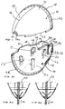
- the one edge interconnecting the top edge 18 and the bottom edge 20 is designated the reference numeral 22 and as illustrated in Fig. 2, the edge 22 is provided with two inner arresting flanges 24 serving to fit into and rest in a pair of inner surface recesses 26 provided at the opposite edge 28 of the body part 10. As is illustrated in Fig. 2, the opposite edge 28 is further provided with two additional flanges 30, serving the purpose of fitting into and resting within corresponding recesses at the inner surface at the edge 22.
- a number of cut-outs 32 are shown provided at the upper edge 18 of the body part 10, which cut-outs serve the purpose of facilitating passage of a gas, such as smoke from a fire through the housing.
- a particular feature of the housing assembled from two body parts 10 relates to the safe and reliable fixation of the housing composed of two body parts relative to the electric cable or cord, the distant end of which is connected to en electrical lamp or similar appliance and the proximal end of which is hidden within the inner chamber defined within the housing as the proximal end is connected to the permanent installation of the room.
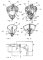
- the first and presently preferred embodiment of the housing for use as or according to the present invention described above with reference to Figs. 1, 2, 3a and 3b and being implemented as a two part structure may be modified in numerous ways, e.g. in accordance with the fittings described in inventor's non-published EP-A 0438025.1 and inventor's previously published international patent application WO 96/21123 to which reference is made, and which specifications are to be considered part of the present specification.
- the outer shell of the housing is constituted by an integral unitary structure as is illustrated in Fig. 5 in which the shell is designated the reference numeral 10'.
- components or elements identical to components or elements, respectively, described above are designated the same reference numerals, whereas components or elements serving the same purpose as components or elements, respectively, previously described, however, geometrically differing from the previously described components or elements, respectively, are designated the same reference numerals, however added a marking identifying the geometrical difference.
- the flexible barb-like arresting arms 34 characteristic of the present invention are integrally included in the body part 10
- the barb-like arresting arms of the embodiment shown in Fig. 5 are included in a separate component 50 which is snapfitted into the interior of the shell 10'.
- the component 50 is produced in a separate moulding process and includes a ring-shaped body 52 from which a total of four arms 34' extend downwards serving the same purpose as the arm 34 described above with reference to Figs. 3a and 3b.
- ring-shaped body 50 is shown in greater details illustrating the angular orientation of the arms 34' and further the snapfitting of the ring-shaped body 50 to the inner surface of the fitting 10' behind a circumferential rim 48 at the inner surface of the shell 10'.
- the structure described above with reference to Figs. 1, 2, 3a and 3b may be modified by the introduction of a separate arresting ring similar to the ring 50, and similarly, the integral arresting arms 34 described above with reference to the first embodiment shown in Figs. 1 and 2 may be integrated into the unitary structure embodiment 10' shown in Figs. 4 and 5.
- the integration of the arms 34 into the embodiment shown in Fig. 4 may cause severe problems in the moulding process and necessitate the use of a highly advanced and elaborate injection moulding tube.
- a gas detector enclosed in a housing according to the invention may be used for sending an alarm signal, if there is an undesirable concentration of a gas for example chlorine or CO in a room.
- a burglary alarm sending and/or receiving radiation such as infra-red radiation can be enclosed in a housing according to the invention, which has been suitably designed with openings wherethrough infra-ref radiation can pass so that the alarm is activated, if the infra-red radiation is disturbed by an intruder.
- a burglary alarm enclosed in a housing according to the invention cannot be observed by an intruder who might otherwise try to interrupt the alarm.
Landscapes
- Business, Economics & Management (AREA)
- Emergency Management (AREA)
- Physics & Mathematics (AREA)
- General Physics & Mathematics (AREA)
- Chemical & Material Sciences (AREA)
- Analytical Chemistry (AREA)
- Fire Alarms (AREA)
- Fire-Detection Mechanisms (AREA)
- Burglar Alarm Systems (AREA)
Priority Applications (12)
| Application Number | Priority Date | Filing Date | Title |
|---|---|---|---|
| EP05020659A EP1768075A1 (de) | 2005-09-22 | 2005-09-22 | Alarmvorrichtung und Gehäuse für eine Alarmvorrichtung |
| CNA2006800352428A CN101283385A (zh) | 2005-09-22 | 2006-09-20 | 报警设备和用于报警设备的壳体 |
| AU2006294202A AU2006294202B2 (en) | 2005-09-22 | 2006-09-20 | Alarm device and housing for an alarm device |
| KR1020087009473A KR20080058418A (ko) | 2005-09-22 | 2006-09-20 | 경보 장치 및 경보 장치용 하우징 |
| PCT/DK2006/000517 WO2007033672A1 (en) | 2005-09-22 | 2006-09-20 | Alarm device and housing for an alarm device |
| DE602006006863T DE602006006863D1 (de) | 2005-09-22 | 2006-09-20 | Alarmeinrichtung und gehäuse für eine alarmeinrichtung |
| DK06791417T DK1943630T3 (da) | 2005-09-22 | 2006-09-20 | Alarmindretning og hus til en alarmindretning |
| CA2623264A CA2623264C (en) | 2005-09-22 | 2006-09-20 | Alarm device and housing for an alarm device |
| EP06791417A EP1943630B1 (de) | 2005-09-22 | 2006-09-20 | Alarmeinrichtung und gehäuse für eine alarmeinrichtung |
| JP2008531531A JP2009509252A (ja) | 2005-09-22 | 2006-09-20 | 警報装置、及び、警報装置のためのハウジング |
| AT06791417T ATE431604T1 (de) | 2005-09-22 | 2006-09-20 | Alarmeinrichtung und gehäuse für eine alarmeinrichtung |
| US11/534,369 US7566830B2 (en) | 2005-03-21 | 2006-09-22 | Alarm device and housing for an alarm device |
Applications Claiming Priority (1)
| Application Number | Priority Date | Filing Date | Title |
|---|---|---|---|
| EP05020659A EP1768075A1 (de) | 2005-09-22 | 2005-09-22 | Alarmvorrichtung und Gehäuse für eine Alarmvorrichtung |
Publications (1)
| Publication Number | Publication Date |
|---|---|
| EP1768075A1 true EP1768075A1 (de) | 2007-03-28 |
Family
ID=36013335
Family Applications (2)
| Application Number | Title | Priority Date | Filing Date |
|---|---|---|---|
| EP05020659A Withdrawn EP1768075A1 (de) | 2005-03-21 | 2005-09-22 | Alarmvorrichtung und Gehäuse für eine Alarmvorrichtung |
| EP06791417A Not-in-force EP1943630B1 (de) | 2005-09-22 | 2006-09-20 | Alarmeinrichtung und gehäuse für eine alarmeinrichtung |
Family Applications After (1)
| Application Number | Title | Priority Date | Filing Date |
|---|---|---|---|
| EP06791417A Not-in-force EP1943630B1 (de) | 2005-09-22 | 2006-09-20 | Alarmeinrichtung und gehäuse für eine alarmeinrichtung |
Country Status (11)
| Country | Link |
|---|---|
| US (1) | US7566830B2 (de) |
| EP (2) | EP1768075A1 (de) |
| JP (1) | JP2009509252A (de) |
| KR (1) | KR20080058418A (de) |
| CN (1) | CN101283385A (de) |
| AT (1) | ATE431604T1 (de) |
| AU (1) | AU2006294202B2 (de) |
| CA (1) | CA2623264C (de) |
| DE (1) | DE602006006863D1 (de) |
| DK (1) | DK1943630T3 (de) |
| WO (1) | WO2007033672A1 (de) |
Cited By (1)
| Publication number | Priority date | Publication date | Assignee | Title |
|---|---|---|---|---|
| WO2020084010A1 (en) * | 2018-10-25 | 2020-04-30 | O&G Research & Development Ab | Safety device for a fire detector |
Families Citing this family (6)
| Publication number | Priority date | Publication date | Assignee | Title |
|---|---|---|---|---|
| TW200736541A (en) * | 2006-03-21 | 2007-10-01 | Forward Electronics Co Ltd | A lamp set with an alarm function |
| US8350712B2 (en) * | 2009-10-27 | 2013-01-08 | Gregory Chero | Emergency alarm with a light to pinpoint the location of an occupant |
| US20140017989A1 (en) * | 2012-07-16 | 2014-01-16 | Solar Turbines Inc. | Power system enclosure |
| CN105491918A (zh) * | 2013-08-27 | 2016-04-13 | 霍利烟雾报警器股份有限公司 | 烟雾报警器安装和拆卸系统以及方法 |
| US20190130717A1 (en) * | 2016-02-10 | 2019-05-02 | Holy Smoke Alarms Pty Ltd. | Smoke Alarm Mounting and Dismounting System and Method |
| US11359941B1 (en) * | 2021-05-14 | 2022-06-14 | SimpliSafe, Inc. | Smoke detector housing and surface mount |
Citations (2)
| Publication number | Priority date | Publication date | Assignee | Title |
|---|---|---|---|---|
| GB2290900A (en) * | 1994-06-20 | 1996-01-10 | Timothy James Shepherd | Lighting smoke alarm |
| US6317054B1 (en) * | 1997-12-11 | 2001-11-13 | Groenstedt Rickard | Fire alarm |
Family Cites Families (2)
| Publication number | Priority date | Publication date | Assignee | Title |
|---|---|---|---|---|
| DE20211456U1 (de) * | 2002-07-11 | 2002-10-02 | Baer, Heike, 44359 Dortmund | Deckenlampe mit integriertem Rauchmelder |
| EP1580481A1 (de) * | 2004-03-23 | 2005-09-28 | Tophat ApS | Deckenleuchte oder Abdeckung |
-
2005
- 2005-09-22 EP EP05020659A patent/EP1768075A1/de not_active Withdrawn
-
2006
- 2006-09-20 WO PCT/DK2006/000517 patent/WO2007033672A1/en not_active Ceased
- 2006-09-20 DE DE602006006863T patent/DE602006006863D1/de active Active
- 2006-09-20 AU AU2006294202A patent/AU2006294202B2/en not_active Ceased
- 2006-09-20 CA CA2623264A patent/CA2623264C/en not_active Expired - Fee Related
- 2006-09-20 KR KR1020087009473A patent/KR20080058418A/ko not_active Withdrawn
- 2006-09-20 JP JP2008531531A patent/JP2009509252A/ja not_active Ceased
- 2006-09-20 DK DK06791417T patent/DK1943630T3/da active
- 2006-09-20 AT AT06791417T patent/ATE431604T1/de not_active IP Right Cessation
- 2006-09-20 EP EP06791417A patent/EP1943630B1/de not_active Not-in-force
- 2006-09-20 CN CNA2006800352428A patent/CN101283385A/zh active Pending
- 2006-09-22 US US11/534,369 patent/US7566830B2/en not_active Expired - Fee Related
Patent Citations (2)
| Publication number | Priority date | Publication date | Assignee | Title |
|---|---|---|---|---|
| GB2290900A (en) * | 1994-06-20 | 1996-01-10 | Timothy James Shepherd | Lighting smoke alarm |
| US6317054B1 (en) * | 1997-12-11 | 2001-11-13 | Groenstedt Rickard | Fire alarm |
Cited By (1)
| Publication number | Priority date | Publication date | Assignee | Title |
|---|---|---|---|---|
| WO2020084010A1 (en) * | 2018-10-25 | 2020-04-30 | O&G Research & Development Ab | Safety device for a fire detector |
Also Published As
| Publication number | Publication date |
|---|---|
| ATE431604T1 (de) | 2009-05-15 |
| AU2006294202A1 (en) | 2007-03-29 |
| US20070069912A1 (en) | 2007-03-29 |
| EP1943630B1 (de) | 2009-05-13 |
| DK1943630T3 (da) | 2009-09-07 |
| KR20080058418A (ko) | 2008-06-25 |
| AU2006294202B2 (en) | 2010-12-16 |
| EP1943630A1 (de) | 2008-07-16 |
| US7566830B2 (en) | 2009-07-28 |
| CN101283385A (zh) | 2008-10-08 |
| WO2007033672A1 (en) | 2007-03-29 |
| CA2623264C (en) | 2012-06-05 |
| JP2009509252A (ja) | 2009-03-05 |
| DE602006006863D1 (de) | 2009-06-25 |
| CA2623264A1 (en) | 2007-03-29 |
Similar Documents
| Publication | Publication Date | Title |
|---|---|---|
| US6492907B1 (en) | Detector system | |
| US6175309B1 (en) | 270 degree motion sensor | |
| EP0346152A2 (de) | Rauchfühler und Schaltungsanordnung | |
| US7414538B2 (en) | Detector assembly suited to smoke alarms | |
| US4796015A (en) | Combination electric clock and smoke detector | |
| US11318485B2 (en) | Smoke generator with deflector | |
| CA2623264C (en) | Alarm device and housing for an alarm device | |
| EP2500639A2 (de) | Eingebauter Rauch- bzw. Wärmemelder | |
| US20080210839A1 (en) | Smoke detector recessed box | |
| US6075447A (en) | Smoke detecting christmas tree ornament system | |
| US20070008710A1 (en) | Emergency and low-lighting system | |
| WO1990001201A1 (en) | Warning device | |
| US7439445B2 (en) | Ceiling fitting or cover | |
| GB2189634A (en) | Fire protection device | |
| WO1999019666A1 (en) | Lamp fitting and monitoring device | |
| CN216253472U (zh) | 一种可与86盒共用的烟雾报警器 | |
| GB2513201A (en) | A Wiring Connection | |
| AU2008100363A4 (en) | Detector assembly suited to smoke alarms | |
| JP2005044139A (ja) | 火災感知器 | |
| AU604160B2 (en) | Monitoring device | |
| CA2309514A1 (en) | 270 motion sensor | |
| AU2008200075B1 (en) | Alarm device | |
| HK1082834B (en) | Detector assembly suited to smoke alarms | |
| KR20070001080U (ko) | 방범기능과 기립형태 구조를 갖는 실내무드등 | |
| HK1100234A (en) | Detector assembly suited to smoke alarms |
Legal Events
| Date | Code | Title | Description |
|---|---|---|---|
| PUAI | Public reference made under article 153(3) epc to a published international application that has entered the european phase |
Free format text: ORIGINAL CODE: 0009012 |
|
| AK | Designated contracting states |
Kind code of ref document: A1 Designated state(s): AT BE BG CH CY CZ DE DK EE ES FI FR GB GR HU IE IS IT LI LT LU LV MC NL PL PT RO SE SI SK TR |
|
| AX | Request for extension of the european patent |
Extension state: AL BA HR MK YU |
|
| AKX | Designation fees paid | ||
| REG | Reference to a national code |
Ref country code: DE Ref legal event code: 8566 |
|
| STAA | Information on the status of an ep patent application or granted ep patent |
Free format text: STATUS: THE APPLICATION IS DEEMED TO BE WITHDRAWN |
|
| 18D | Application deemed to be withdrawn |
Effective date: 20070929 |