EP1768084A1 - Vorrichtung zur Darstellung von Informationen - Google Patents
Vorrichtung zur Darstellung von Informationen Download PDFInfo
- Publication number
- EP1768084A1 EP1768084A1 EP06300872A EP06300872A EP1768084A1 EP 1768084 A1 EP1768084 A1 EP 1768084A1 EP 06300872 A EP06300872 A EP 06300872A EP 06300872 A EP06300872 A EP 06300872A EP 1768084 A1 EP1768084 A1 EP 1768084A1
- Authority
- EP
- European Patent Office
- Prior art keywords
- fabric
- translucent
- presentation
- information according
- transparent
- Prior art date
- Legal status (The legal status is an assumption and is not a legal conclusion. Google has not performed a legal analysis and makes no representation as to the accuracy of the status listed.)
- Withdrawn
Links
- 239000004744 fabric Substances 0.000 claims description 44
- 230000002787 reinforcement Effects 0.000 claims description 8
- 230000002093 peripheral effect Effects 0.000 claims description 7
- 229920002994 synthetic fiber Polymers 0.000 claims description 5
- VVQNEPGJFQJSBK-UHFFFAOYSA-N Methyl methacrylate Chemical compound COC(=O)C(C)=C VVQNEPGJFQJSBK-UHFFFAOYSA-N 0.000 claims description 3
- 229920005372 Plexiglas® Polymers 0.000 claims description 3
- 238000005286 illumination Methods 0.000 claims description 3
- 239000004417 polycarbonate Substances 0.000 claims description 3
- 229920000515 polycarbonate Polymers 0.000 claims description 3
- 230000014759 maintenance of location Effects 0.000 claims 1
- 239000000463 material Substances 0.000 abstract description 6
- 230000000694 effects Effects 0.000 description 2
- 238000004519 manufacturing process Methods 0.000 description 2
- 238000004026 adhesive bonding Methods 0.000 description 1
- 238000012423 maintenance Methods 0.000 description 1
- 229920003023 plastic Polymers 0.000 description 1
- 239000004033 plastic Substances 0.000 description 1
Images

Classifications
-
- G—PHYSICS
- G09—EDUCATION; CRYPTOGRAPHY; DISPLAY; ADVERTISING; SEALS
- G09F—DISPLAYING; ADVERTISING; SIGNS; LABELS OR NAME-PLATES; SEALS
- G09F13/00—Illuminated signs; Luminous advertising
- G09F13/04—Signs, boards or panels, illuminated from behind the insignia
- G09F13/0409—Arrangements for homogeneous illumination of the display surface, e.g. using a layer having a non-uniform transparency
-
- G—PHYSICS
- G09—EDUCATION; CRYPTOGRAPHY; DISPLAY; ADVERTISING; SEALS
- G09F—DISPLAYING; ADVERTISING; SIGNS; LABELS OR NAME-PLATES; SEALS
- G09F13/00—Illuminated signs; Luminous advertising
- G09F13/04—Signs, boards or panels, illuminated from behind the insignia
- G09F13/0418—Constructional details
- G09F13/0468—Signs, boards or panels with tensioned or flexible display surface
-
- G—PHYSICS
- G09—EDUCATION; CRYPTOGRAPHY; DISPLAY; ADVERTISING; SEALS
- G09F—DISPLAYING; ADVERTISING; SIGNS; LABELS OR NAME-PLATES; SEALS
- G09F13/00—Illuminated signs; Luminous advertising
- G09F13/04—Signs, boards or panels, illuminated from behind the insignia
- G09F13/08—Signs, boards or panels, illuminated from behind the insignia using both translucent and non-translucent layers
-
- G—PHYSICS
- G09—EDUCATION; CRYPTOGRAPHY; DISPLAY; ADVERTISING; SEALS
- G09F—DISPLAYING; ADVERTISING; SIGNS; LABELS OR NAME-PLATES; SEALS
- G09F13/00—Illuminated signs; Luminous advertising
- G09F13/04—Signs, boards or panels, illuminated from behind the insignia
- G09F13/08—Signs, boards or panels, illuminated from behind the insignia using both translucent and non-translucent layers
- G09F13/10—Signs, boards or panels, illuminated from behind the insignia using both translucent and non-translucent layers using transparencies
-
- G—PHYSICS
- G09—EDUCATION; CRYPTOGRAPHY; DISPLAY; ADVERTISING; SEALS
- G09F—DISPLAYING; ADVERTISING; SIGNS; LABELS OR NAME-PLATES; SEALS
- G09F13/00—Illuminated signs; Luminous advertising
- G09F13/18—Edge-illuminated signs
- G09F2013/1804—Achieving homogeneous illumination
-
- G—PHYSICS
- G09—EDUCATION; CRYPTOGRAPHY; DISPLAY; ADVERTISING; SEALS
- G09F—DISPLAYING; ADVERTISING; SIGNS; LABELS OR NAME-PLATES; SEALS
- G09F13/00—Illuminated signs; Luminous advertising
- G09F13/18—Edge-illuminated signs
- G09F2013/184—Information to display
- G09F2013/1845—Interchangeable poster
Definitions
- the present invention relates to a device for the presentation of information.
- This invention relates to the field of manufacturing devices designed to present information, more particularly information of a technical, commercial or advertising type. This invention will find a particular application in the form of a presentation booth such as a fair stand.
- information presentation devices adopting the shape of a three-dimensional object, including a housing or the like, comprising a plurality of sides, at least some of which are made of a translucent material and on which include information more particularly made visible under the effect of lighting means that internally includes such a device and which provide the backlight of such a side.
- the sides made of a translucent material are usually constituted by a panel of synthetic material encased in a frame or attached to a rigid structure. This frame or this rigid structure is visible, especially at the rear of such a translucent panel, which, particularly at the junction between two backlit sides, is particularly unsightly.
- the present invention is intended to overcome the disadvantages of devices of the state of the art through a new information presentation device.
- the invention relates to a device for the presentation of information comprising, on the one hand, at least two adjacent sides each constituted by a wall translucent, on the other hand, a structure receiving such a translucent wall and, secondly and internally, means for providing illumination from the rear of the translucent walls, characterized in that it comprises a translucent fabric, constituting the walls of the sides of the device, and stretched over the structure formed, at least at the junction of the walls of the adjacent sides, by a transparent or translucent reinforcement.
- the advantages of the present invention consist in that the transparent or translucent reinforcement passes most or all of the light emitted by the backlighting means. Such an armature is then not visible at the back of the fabric, more particularly at the junction of two adjacent sides.
- the present invention relates to the field of manufacturing devices designed to present information, more particularly information of a technical, commercial or advertising type. If, in the remainder of the description, reference will be made in particular to an information presentation device adopting the form of a stand, especially a fair stand, the present invention is in no way limited thereto.
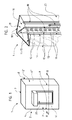
- an information presentation device 1 which adopts the shape of a three-dimensional object (for example a parallelepipedal object) comprising a plurality of sides 2, 2 ', 2' 'of which at least two 2 , 2 '; 2 ', 2' 'are adjacent.
- a three-dimensional object for example a parallelepipedal object
- This device 1 comprises a structure 3 covered by translucent walls 4, 4 ', 4 "constituting, each, a side 2, 2', 2" of this device 1 and on which there is an information.
- the walls 4, 4 ', 4 "of the sides 2, 2', 2" of this device 1 are, in fact, constituted by at least one translucent fabric 5 stretched over said structure 3 and on which are the information appearing on the different sides 2, 2 ', 2' 'of the device 1.
- all the walls 4, 4', 4 "of the device 1 is constituted by a single, translucent fabric 5 stretched over said structure 3.
- the device 1, more particularly the fabric 5 itself, comprises means 6 for putting the fabric 5 under tension over at least part of the structure 3, more particularly over at least an element of this structure 3.
- Such means 6 of tensioning can take the form of at least one elastic means equipping the fabric 5 at or near the longitudinal edge 7 and / or the side edge 8 of such a fabric 5, this on at least a part (but preferably on the entirety) of the perimeter of this canvas 5.
- a preferred embodiment consists in that the elastic means adopts the shape of an elastic rope (tensioner or similar type) passing through openings in the fabric 5, more particularly in the vicinity of the longitudinal edge 7 and / or lateral 8 of the canvas 5.
- such a fabric 5 is stretched over said structure 3 in the manner of a cover.
- such a fabric 5 may advantageously be at least partly of extensible type.
- Such a fabric 5 is made at least partly of fabric and / or at least partly of a synthetic material, in particular a plastic material.
- the fabric is made of a coated fabric and / or covered with a synthetic material, more particularly a plasticized fabric, in particular using PVC.
- Such a plasticized fabric may then advantageously be of the extensible type.
- such a fabric 5 is stretched over a structure 3 which is, in fact, constituted by a plurality of reinforcements 10, 10 ', in particular assembled so as to define a frame, a framework or the like, and over which is stretched the translucent canvas 5.
- this structure 3 is constituted, at least at the junction 9 of the walls 4; 4 ', 4'; 4 '' of adjacent sides 2, 2 '; 2 ', 2' ', by a transparent or translucent reinforcement 10 over which said web 5 is stretched.
- Such an embodiment advantageously makes it possible to make said armature 10 invisible to the back of the fabric 5 for the observer, this at least at the junction of the walls 4; 4 ', 4'; 4 '' of adjacent sides 2, 2 '; 2 ', 2' '.
- the structure 3 is still constituted, in particular near the longitudinal edges 7 and / or lateral 8 of the stretched fabric 5, by at least one peripheral reinforcement 10 'over which is stretched longitudinally and or laterally said web 5, more particularly the longitudinal edge 7 and / or lateral 8 thereof 5.
- such a peripheral armature 10 'can again, be transparent or translucent which makes this peripheral armature 10' invisible behind the fabric 5.
- At least part of the frames 10, 10 'of the structure 3, above which the fabric 5 is stretched is constituted by at least one elongated element, more particularly a bar, a tube or the like, in particular transparent or translucent.
- a particular embodiment is that such a frame 10, 10 'transparent or translucent in the form of an elongated element is made of plexiglass, polycarbonate or the like.
- At least part of these plates 10, 10 ', or even the entirety of these plates 10, 10' consists of a plate 11, 11 '. in contact with the stretched canvas 5.
- the armature 10 that includes the structure 3 at the junction 9 between the walls 4; 4 ', 4'; 4 "of two adjacent sides 2, 2 '; 2', 2" is then constituted by a transparent or translucent plate 11 in contact with the stretched fabric 5.
- peripheral armatures 10 ' these can, depending on the case, be constituted by an opaque plate 11' (appended figures) or by a transparent or translucent plate in contact with the stretched fabric 5.
- such a plate 11, 11 ' may have a curvature, conferring on such a plate 11, 11' in the form of a longitudinal portion of tube, and above which said fabric 5 is stretched .
- such a plate 11, 11 ' extends in a plane forming an angle with at least one of the walls 4, 4', 4 '' of the device 1.
- a preferred embodiment illustrated in the appended figures is that such a plate 11 extends according to a plane forming an angle (preferably close, or even identical) with the walls 4; 4 ', 4'; 4 "of two adjacent sides 2, 2 ', 2', 2" of the device 1.
- This embodiment advantageously allows to distribute the forces exerted on such a plate 11 by the canvas 5 under tension.
- such a plate 11, 11 comprises a ring 13, preferably of rounded shape, over which the fabric 5 is stretched.
- the plate 11, 11 'transparent or translucent it may be constituted by a plexiglass plate, polycarbonate or the like.
- the device 1 comprises means 14 for mounting the transparent or translucent plate 11 constituting the armature 10 that the structure 3 comprises at the junction 9 of the walls 2, 2 '; 2 ', 2 "adjacent sides 4, 4', 4 ', 4".
- These mounting means 14 are, at least in part, constituted by lateral holding means 15 of such a plate 11.
- lateral holding means 15 may be in the form of at least one "U" -shaped piece. , inside which is engaged said plate 11, and secured to a support member 16 that includes the device 1, in particular in the upper part and in the lower part.
- such a support member 16 is defined by a plate 11 'constituting a peripheral reinforcement 10' as mentioned above.
- these mounting means 14 of the transparent or translucent plate 11 can, again, include a wing 17 extending longitudinally with respect to this plate 11 and made integral (including bolting, riveting, gluing or other) of the latter 11.
- All of these mounting means 14 advantageously make it possible to stiffen the transparent or translucent plate 11 so as to avoid (or at least reduce) its deformation under the effect of the stresses exerted on this plate 11 by the fabric 5 under power.
- the device 1 comprises lighting means 18 of said fabric 5 designed to provide illumination from the back of this fabric 5 (backlight).
- Such lighting means 18 are then implanted internally to said device 1.
- such lighting means 18 can be arranged only on the same side of such a frame 10. However, and according to a preferred embodiment of the invention, the invention illustrated in the appendix, such lighting means 18 are arranged on either side of a frame 10 constituted by such a transparent or translucent plate 11.
- the device 1 comprises, internally, means 19 for fixing, externally to the device 1 and on the latter 1, an object 20.
- Such a fixation is then realized through the web 5 which may comprise, for this purpose, orifices for the passage of fasteners.
- these fixing means 19 may, again, be translucent or transparent so as to be invisible to an observer.
- the device 1 comprises, again, a frame 21, in particular constituted by at least one tubular element 22, or even by an assembly of tubular elements 22, 22 '. It is, more particularly, of such a frame 21 that are secured to or the support members 16, or the frames 10, 10 'of the structure 3, the wing 17 of the mounting means 14, the means of 18, the fastening means 19, or even a bottom 23 that includes this device 1.
Landscapes
- Physics & Mathematics (AREA)
- General Physics & Mathematics (AREA)
- Engineering & Computer Science (AREA)
- Theoretical Computer Science (AREA)
- Illuminated Signs And Luminous Advertising (AREA)
Applications Claiming Priority (1)
| Application Number | Priority Date | Filing Date | Title |
|---|---|---|---|
| FR0552839A FR2891387B1 (fr) | 2005-09-23 | 2005-09-23 | Dispositif pour la presentation d'informations |
Publications (1)
| Publication Number | Publication Date |
|---|---|
| EP1768084A1 true EP1768084A1 (de) | 2007-03-28 |
Family
ID=36388400
Family Applications (1)
| Application Number | Title | Priority Date | Filing Date |
|---|---|---|---|
| EP06300872A Withdrawn EP1768084A1 (de) | 2005-09-23 | 2006-08-09 | Vorrichtung zur Darstellung von Informationen |
Country Status (2)
| Country | Link |
|---|---|
| EP (1) | EP1768084A1 (de) |
| FR (1) | FR2891387B1 (de) |
Cited By (2)
| Publication number | Priority date | Publication date | Assignee | Title |
|---|---|---|---|---|
| EP2157361A1 (de) * | 2008-08-22 | 2010-02-24 | Normalu | Leuchtkasten mit unsichtbaren |
| EP2306439A1 (de) * | 2009-10-01 | 2011-04-06 | Cap | Dreidimensionale Anzeigevorrichtung |
Citations (3)
| Publication number | Priority date | Publication date | Assignee | Title |
|---|---|---|---|---|
| EP0697281A1 (de) * | 1994-08-15 | 1996-02-21 | Oji Yuka Goseishi Co., Ltd. | Folie für beleuchtete Anzeigetafel |
| US6070351A (en) * | 1998-08-24 | 2000-06-06 | Verret; Normand | Flexible face sign with raised display surface |
| US20040257803A1 (en) * | 2003-06-23 | 2004-12-23 | Brilliant Ideas And Design, Llc | Ceiling light illuminated display |
-
2005
- 2005-09-23 FR FR0552839A patent/FR2891387B1/fr not_active Expired - Fee Related
-
2006
- 2006-08-09 EP EP06300872A patent/EP1768084A1/de not_active Withdrawn
Patent Citations (3)
| Publication number | Priority date | Publication date | Assignee | Title |
|---|---|---|---|---|
| EP0697281A1 (de) * | 1994-08-15 | 1996-02-21 | Oji Yuka Goseishi Co., Ltd. | Folie für beleuchtete Anzeigetafel |
| US6070351A (en) * | 1998-08-24 | 2000-06-06 | Verret; Normand | Flexible face sign with raised display surface |
| US20040257803A1 (en) * | 2003-06-23 | 2004-12-23 | Brilliant Ideas And Design, Llc | Ceiling light illuminated display |
Cited By (4)
| Publication number | Priority date | Publication date | Assignee | Title |
|---|---|---|---|---|
| EP2157361A1 (de) * | 2008-08-22 | 2010-02-24 | Normalu | Leuchtkasten mit unsichtbaren |
| FR2935169A1 (fr) * | 2008-08-22 | 2010-02-26 | Normalu | Caisson lumineux a bords invisibles |
| EP2306439A1 (de) * | 2009-10-01 | 2011-04-06 | Cap | Dreidimensionale Anzeigevorrichtung |
| FR2951007A1 (fr) * | 2009-10-01 | 2011-04-08 | Cap | Dispositif d'affichage tridimensionnel |
Also Published As
| Publication number | Publication date |
|---|---|
| FR2891387B1 (fr) | 2007-11-30 |
| FR2891387A1 (fr) | 2007-03-30 |
Similar Documents
| Publication | Publication Date | Title |
|---|---|---|
| FR2839430A1 (fr) | Dispositif de mise en place de fixation de toiles sur des structures receptrices d'ameublement d'equipement mobilier et d'assise | |
| CA2743384C (fr) | Plaque lumineuse | |
| WO2018007125A1 (fr) | Dispositif de fausse-paroi lumineuse | |
| EP4627256A1 (de) | Beleuchtungseinrichtung für ein kraftfahrzeug | |
| EP1768084A1 (de) | Vorrichtung zur Darstellung von Informationen | |
| EP2993280B1 (de) | Röhrenförmiger leuchtbalken für 3d-struktur, und 3d-struktur aus gespannter stoffbahn, die einen solchen balken umfasst | |
| FR2970011A1 (fr) | Dispositif lumineux destine a etre integre a une fausse paroi et permettant d'obtenir un effet esthetique en trois dimensions | |
| US20170178550A1 (en) | Backlit display system | |
| CA2928151A1 (fr) | Systeme et methode d'assemblage prefabrique de cadres | |
| FR3078430A1 (fr) | Ossature de structure eclairee, et structure eclairee comportant une telle ossature | |
| WO2015036696A1 (fr) | Systeme de fixation pour la realisation de revetements tendus | |
| FR2953702A1 (fr) | Element de mobilier, notamment de mobilier commercial | |
| EP2157361B1 (de) | Leuchtkasten mit unsichtbaren | |
| EP3599118A1 (de) | Baugrupper mit einem fenster zum schliessen eines fahrzeuginnenraums und einer lichtquelle, die von einem am fenster befestigten träger fixiert wird | |
| FR2677479A1 (fr) | Caisson lumineux a eclairage lateral pour enseigne. | |
| FR2951007A1 (fr) | Dispositif d'affichage tridimensionnel | |
| FR2838760A1 (fr) | Dispositif destine a assurer la tension et le libre acces a la face verso d'une toile tendue | |
| FR2831582A1 (fr) | Panneau a paroi souple comportant des moyens de tension permanente | |
| KR200456483Y1 (ko) | 간판 부착장치 | |
| FR2988754A1 (fr) | Abri pour bassin d'agrement | |
| EP3200175A1 (de) | Paneel, das ein element aus flexiblem material umfasst, insbesondere zum bilden einer abdeckung oder einer werbetafel | |
| EP0511123A1 (de) | Rahme für Informations-, Anzeige- und Reklametafeln | |
| EP1398749B1 (de) | Kontrastschirm für Lichtzeichenanlagen | |
| FR2799566A1 (fr) | Support d'affichage polyvalent, notamment pour expositions temporaires | |
| FR2896185A1 (fr) | Chassis pour panneau a tendre |
Legal Events
| Date | Code | Title | Description |
|---|---|---|---|
| PUAI | Public reference made under article 153(3) epc to a published international application that has entered the european phase |
Free format text: ORIGINAL CODE: 0009012 |
|
| AK | Designated contracting states |
Kind code of ref document: A1 Designated state(s): AT BE BG CH CY CZ DE DK EE ES FI FR GB GR HU IE IS IT LI LT LU LV MC NL PL PT RO SE SI SK TR |
|
| AX | Request for extension of the european patent |
Extension state: AL BA HR MK YU |
|
| 17P | Request for examination filed |
Effective date: 20070918 |
|
| 17Q | First examination report despatched |
Effective date: 20071018 |
|
| AKX | Designation fees paid |
Designated state(s): AT BE BG CH CY CZ DE DK EE ES FI FR GB GR HU IE IS IT LI LT LU LV MC NL PL PT RO SE SI SK TR |
|
| STAA | Information on the status of an ep patent application or granted ep patent |
Free format text: STATUS: THE APPLICATION IS DEEMED TO BE WITHDRAWN |
|
| 18D | Application deemed to be withdrawn |
Effective date: 20100302 |