EP1768145B1 - Steuerungssvorrichtung, die einen Mechanismus schwergängiger Stelle umfaßt und elektrische Kontakte betätigt - Google Patents
Steuerungssvorrichtung, die einen Mechanismus schwergängiger Stelle umfaßt und elektrische Kontakte betätigt Download PDFInfo
- Publication number
- EP1768145B1 EP1768145B1 EP06121106A EP06121106A EP1768145B1 EP 1768145 B1 EP1768145 B1 EP 1768145B1 EP 06121106 A EP06121106 A EP 06121106A EP 06121106 A EP06121106 A EP 06121106A EP 1768145 B1 EP1768145 B1 EP 1768145B1
- Authority
- EP
- European Patent Office
- Prior art keywords
- function control
- control member
- elastic
- function
- control device
- Prior art date
- Legal status (The legal status is an assumption and is not a legal conclusion. Google has not performed a legal analysis and makes no representation as to the accuracy of the status listed.)
- Not-in-force
Links
Images

Classifications
-
- H—ELECTRICITY
- H01—ELECTRIC ELEMENTS
- H01H—ELECTRIC SWITCHES; RELAYS; SELECTORS; EMERGENCY PROTECTIVE DEVICES
- H01H13/00—Switches having rectilinearly-movable operating part or parts adapted for pushing or pulling in one direction only, e.g. push-button switch
- H01H13/50—Switches having rectilinearly-movable operating part or parts adapted for pushing or pulling in one direction only, e.g. push-button switch having a single operating member
- H01H13/56—Switches having rectilinearly-movable operating part or parts adapted for pushing or pulling in one direction only, e.g. push-button switch having a single operating member the contact returning to its original state upon the next application of operating force
-
- H—ELECTRICITY
- H01—ELECTRIC ELEMENTS
- H01H—ELECTRIC SWITCHES; RELAYS; SELECTORS; EMERGENCY PROTECTIVE DEVICES
- H01H5/00—Snap-action arrangements, i.e. in which during a single opening operation or a single closing operation energy is first stored and then released to produce or assist the contact movement
- H01H5/04—Energy stored by deformation of elastic members
- H01H5/18—Energy stored by deformation of elastic members by flexing of blade springs
- H01H5/22—Energy stored by deformation of elastic members by flexing of blade springs blade spring with at least one snap-acting leg and at least one separate contact-carrying or contact-actuating leg
Definitions
- the present invention relates to a control device comprising a hard point mechanism and actuating electrical contacts.
- Such a control device is usually intended to equip a motor vehicle, for the control of a function such as locking / unlocking the doors of this motor vehicle.
- the hard point means has an ergonomic function, allowing a user to feel a slight resistance to touch when activating the function control member.
- These hard point means comprise complementary cams usually formed by a finger, carried by the function control member, and a complementary spring carried by the fixed support.
- the electrical contact control member is movably mounted relative to the fixed support between first and second positions.
- the function controlled by the control device is in a first state (opening locked) when the electrical contact control member is in its first position, and in a second state (unlocked opening) when this electrical contact control member is in its second position.
- the spacer member is adapted to transmit the movements of the function control member to the electrical contact control member, so that the electrical contact control member is in its first position when the organ the function control is in its rest position, and in its second position when the function control member is in its active position.
- Indexing the function control member to the active position usually requires that the function control member be movable beyond the active position to its temporary over-travel position.
- the spacer member is elastically deformable to allow this movement between the active position and the over-stroke position.
- the spacer member is a spring, a silicone membrane or a plastic elastic tab, of sufficient stiffness to transmit the movements of the function control member to the electrical contact control member.
- the device therefore comprises multiple elements intended to achieve the hard point and the elastic bracing between the function control member and the electrical contact control member.
- the purpose of the invention is in particular to simplify the structure of a control device of the aforementioned type, so as to reduce the cost and the bulk thereof, by limiting neither the resistance of the elements of this device, nor the life of this device.
- the subject of the invention is a device for controlling a function of the aforementioned type, comprising an elastic member forming both the elastic bracing member and a hard point elastic cam.
- This elastic member is particularly advantageous, since it makes it possible to dispense with the multiple conventional elements forming the elastic bracing member and the hard point elastic cam.
- the structure of the device is simplified, which facilitates the manufacture of the device and reduces its cost, since the elastic member can be mounted in the device in a single operation.
- the control device 10 is usually intended to control a function implemented by an electrical equipment 11, such as the locking / unlocking of the opening of this motor vehicle.
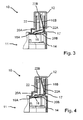
- the control device 10 comprises a function control member 12 mounted movably in translation on a fixed support 14 between a rest position, represented on the figure 1 , an indexed active position, represented on the figure 3 , and a position of temporary over-stroke, opposite to the rest position, shown on the figure 4 .
- Conventional indexing means I of the function control member 12 in the active position are arranged between this function control member 12 and the support 14.
- Elastic means 15 for returning the function control member 12 to its rest position are also arranged between the function control member 12 and the support 14.
- these elastic means 15 comprise a compression spring in bearing on a first seat formed on the function control member 12 and a second seat formed on the support 14.
- the fixed support 14 forms a hollow body in which is housed an elastic member 16, preferably metal, generally shaped folded strip.
- the elastic member 16 has a fastening portion 17 on the support 14, connecting first 16A and second 16B parts of the elastic member 16.
- the fixing portion 17 is for example fixed to the support 14 by gluing or pegging.
- the first part 16A forms a resilient bracing member between the function control member 12 and an electrical contact control member 18 of the electrical equipment 11, able to move relative to the support 14 between a first position, wherein the electrical equipment 11 is in a first state, and a second position, in which the electrical equipment 11 is in a second state.
- the spacer member 16A has a general shape of elastically deformable pin-folded band so as to form first 20A and second 20B branches.
- the first branch 20A of the spacer member 16A is intended to cooperate with a free engagement end 22A of a finger 22 when the function control member 12 is between its active position and its over-stroke position.
- the finger 22 is connected to the function control member 12 by a connecting end 22B of the finger 22.
- the second branch 20B of the spacer member 16A is intended to cooperate with the electrical contact control member 18 when the function control member 12 is between its active position and its over-stroke position.
- first 20A and second 20B branches of the spacer member 16A is likely to vary elastically when the function control member 12 moves between its active position and its over-stroke position.
- the second portion 16B of the elastic member 16 forms an elastic blade, provided with a connecting end to the fixing portion 17 and a bearing end on the finger 22.
- Hard point means 23 are arranged on the bearing end of this second part 16B of the elastic member 16 and the finger 22.
- the hard point forming means 23 comprise a hard point cam profile 24, forming a hard point rigid cam, formed between the cooperation 22A and the connection 22B end of the finger 22, intended to cooperate with a complementary elastic cam. 26 of hard point formed on the bearing end of the second portion 16B of the elastic member 16,
- the complementary cams 24, 26 of hard point are shaped so that the means 23 forming hard point are activated during the movement of the function control member 12 from its rest position to its active position.
- the elastic member 16 forms both the elastic bracing member 16A and the elastic hard point cam 26.
- control device 10 The main aspects of the operation of the control device 10 related to the invention will be specified below.
- the control device 10 is initially considered in a rest position represented on the figure 1 in which the function control member 12 is in its rest position.
- the hard point complementary cams 24, 26 cooperate with each other so as to generate a hard point effect.
- the spacer member 16A fixed to the support 14 by the fastening portion 17, cooperates neither with the electrical contact control member 18 nor with the engagement end 22A of the finger 22.
- the function control member 12 moves in translation towards its active position, as shown in FIG. figure 2 .
- the hard point complementary cams 24, 26 then slide on each other until the function control member 12 has moved a predetermined stroke, from which the hard point complementary cams 24, 26 no longer cooperate with each other.
- the elastic cam 26 cooperates with a surface of the finger 22 parallel to the direction of movement of the function control member 12, and therefore no longer opposes the movement of this function control member 12.
- This spacer member 16A then tilts around the fastening portion 17, and the second branch 22B cooperates with the electrical contact control member 18, and pushes it to its second position.
- the electrical equipment 11 then goes into its second state.
- the spacer member 16A then deforms elastically, the spacing between its first 20A and second 20B branches decreasing elastically.
- the indexing means I when the user releases the function control member 12, the latter goes up to the active position thanks to the elastic return means 15, this position being indexed by the indexing means I.
- a function control device may in particular be intended to control other functions, such as lighting, defrosting a window, air conditioning, etc.
Landscapes
- Lock And Its Accessories (AREA)
- Push-Button Switches (AREA)
- Switches With Compound Operations (AREA)
- Coupling Device And Connection With Printed Circuit (AREA)
- Rotary Switch, Piano Key Switch, And Lever Switch (AREA)
- Braking Arrangements (AREA)
Claims (8)
- Vorrichtung (10) zur Aktivierung einer Funktion, insbesondere einer Funktion, die durch eine elektrische Einrichtung (11) durchgeführt wird, wobei die Vorrichtung Folgendes umfasst:- ein Funktionsaktivierungsglied (12), das an einer feststehenden Stütze (14) zwischen einer Ruheposition, einer geschalteten aktiven Position und einer vorübergehenden, der Ruheposition gegenüberliegenden Überlaufposition bewegbar angebracht ist, und- Schwergangstellenbildungsmittel (23), die bei der Verschiebung des Funktionsaktivierungsglieds (12) aus seiner Ruheposition in seine geschaltete aktive Position durch elastisches Zusammenwirken komplementärer Schwergangstellennocken (24, 26), die am Funktionsaktivierungsglied (12) und an der Stütze (14) vorgesehen sind, aktiviert werden,wobei das Funktionsaktivierungsglied (12) zum Zusammenwirken mit einem Glied (18) zur Aktivierung eines elektrischen Kontakts durch ein elastisches Verstrebungsglied (16A), wenn sich das Funktionsaktivierungsglied (12) zwischen seiner geschalteten aktiven Position und seiner Überlaufposition befindet, bestimmt ist, dadurch gekennzeichnet, dass sie ein elastisches Glied (16) umfasst, das gleichzeitig das elastische Verstrebungsglied (16A) und einen elastischen Schwergangstellennocken (26) bildet.
- Funktionsaktivierungsvorrichtung (10) nach Anspruch 1, dadurch gekennzeichnet, dass das Funktionsaktivierungsglied (12) ein Nockenprofil aufweist, das einen Schwergangnocken (24) bildet, der zum Zusammenwirken mit dem elastischen Schwergangstellennocken (26) bei der Verschiebung des Funktionsaktivierungsglieds (12) aus seiner Ruheposition in seine geschaltete aktive Position bestimmt ist.
- Funktionsaktivierungsvorrichtung (10) nach Anspruch 1 oder 2, dadurch gekennzeichnet, dass das Funktionsaktivierungsglied (12) einen Finger (22) aufweist, der mit einem freien Ende (22A) zum Zusammenwirken mit dem elastischen Verstrebungsglied (16A), wenn sich das Funktionsaktivierungsglied (12) zwischen seiner aktiven Position und seiner Überlaufposition befindet, versehen ist.
- Funktionsaktivierungsvorrichtung (10) nach den Ansprüchen 2 und 3 zusammengenommen, dadurch gekennzeichnet, dass der Finger (22) das Nockenprofil (24) trägt.
- Funktionsaktivierungsvorrichtung (10) nach einem der vorhergehenden Ansprüche, dadurch gekennzeichnet, dass das elastische Glied (16) die allgemeine Form einer gefalteten Bahn aufweist, mit Folgendem:- einem elastisch verformbaren haarnadelförmig gefalteten ersten Teil (16A), um den ersten (20A) und den zweiten (20B) Schenkel zu bilden, die mit dem Funktionsaktivierungsglied (12) bzw. dem Glied (18) zur Aktivierung eines elektrischen Kontakts zusammenwirken sollen, wenn sich das Funktionsaktivierungsglied (12) zwischen seiner aktiven Position und seiner Überlaufposition befindet, und- einem den elastischen Schwergangstellennocken (26) bildenden zweiten Teil (16B).
- Funktionsaktivierungsvorrichtung (10) nach Anspruch 5, dadurch gekennzeichnet, dass das elastische Glied (16) einen Teil (17) zur Befestigung an der Stütze (14) bildet, der den ersten (16A) und den zweiten (16B) Teil dieses elastischen Glieds (16) miteinander verbindet.
- Funktionsaktivierungsvorrichtung (10) nach einem der vorhergehenden Ansprüche, dadurch gekennzeichnet, dass sie zwischen dem Funktionsaktivierungsglied (12) und der Stütze (14) angeordnete Mittel (I) zum Schalten des Funktionsaktivierungsglieds (12) in die aktive Position enthält.
- Funktionsaktivierungsvorrichtung (10) nach einem der vorhergehenden Ansprüche, dadurch gekennzeichnet, dass das elastische Glied (16) aus Metall besteht.
Priority Applications (1)
| Application Number | Priority Date | Filing Date | Title |
|---|---|---|---|
| PL06121106T PL1768145T3 (pl) | 2005-09-23 | 2006-09-22 | Przyrząd sterujący działaniem składający się z mechanizmu miejsca tarcia i uaktywniającego zestyku elektrycznego |
Applications Claiming Priority (1)
| Application Number | Priority Date | Filing Date | Title |
|---|---|---|---|
| FR0509772A FR2891393B1 (fr) | 2005-09-23 | 2005-09-23 | Dispositif de commande comportant un mecanisme de point dur et actionnant des contacts electriques |
Publications (2)
| Publication Number | Publication Date |
|---|---|
| EP1768145A1 EP1768145A1 (de) | 2007-03-28 |
| EP1768145B1 true EP1768145B1 (de) | 2008-04-30 |
Family
ID=36298426
Family Applications (1)
| Application Number | Title | Priority Date | Filing Date |
|---|---|---|---|
| EP06121106A Not-in-force EP1768145B1 (de) | 2005-09-23 | 2006-09-22 | Steuerungssvorrichtung, die einen Mechanismus schwergängiger Stelle umfaßt und elektrische Kontakte betätigt |
Country Status (5)
| Country | Link |
|---|---|
| EP (1) | EP1768145B1 (de) |
| AT (1) | ATE393958T1 (de) |
| DE (1) | DE602006001042T2 (de) |
| FR (1) | FR2891393B1 (de) |
| PL (1) | PL1768145T3 (de) |
Family Cites Families (4)
| Publication number | Priority date | Publication date | Assignee | Title |
|---|---|---|---|---|
| DE3709305A1 (de) * | 1987-03-21 | 1988-09-29 | Mueller Rolf K Dr | Druckschalter, insbesondere als taste einer tastatur |
| US4954675A (en) * | 1987-09-18 | 1990-09-04 | Kabushiki Kaisha Tokai Rika Denki Seisakusho | Switch operation indicator |
| DE8807543U1 (de) * | 1988-06-09 | 1988-08-04 | Hella KG Hueck & Co, 4780 Lippstadt | Pneumatisches Stellelement |
| DE9416060U1 (de) * | 1994-10-05 | 1994-11-24 | Chiang, Li-Ching, Taipeh/T'ai-pei | Tastenschalter mit tonerzeugenden Einrichtungen |
-
2005
- 2005-09-23 FR FR0509772A patent/FR2891393B1/fr not_active Expired - Fee Related
-
2006
- 2006-09-22 PL PL06121106T patent/PL1768145T3/pl unknown
- 2006-09-22 DE DE602006001042T patent/DE602006001042T2/de active Active
- 2006-09-22 AT AT06121106T patent/ATE393958T1/de not_active IP Right Cessation
- 2006-09-22 EP EP06121106A patent/EP1768145B1/de not_active Not-in-force
Also Published As
| Publication number | Publication date |
|---|---|
| EP1768145A1 (de) | 2007-03-28 |
| DE602006001042T2 (de) | 2009-01-02 |
| PL1768145T3 (pl) | 2009-03-31 |
| ATE393958T1 (de) | 2008-05-15 |
| FR2891393B1 (fr) | 2007-12-21 |
| DE602006001042D1 (de) | 2008-06-12 |
| FR2891393A1 (fr) | 2007-03-30 |
Similar Documents
| Publication | Publication Date | Title |
|---|---|---|
| FR2955604A1 (fr) | Poignee de portiere comportant un interrupteur actionne par une partie mobile | |
| EP2858081B1 (de) | Positionsschalter | |
| EP0845718B1 (de) | Elektrische Schaltvorrichtung auf einer gedruckten Schaltung und Uhr, die eine solche Vorrichtung enthält | |
| EP0240778B1 (de) | Drückermechanismus für Uhren | |
| EP1768145B1 (de) | Steuerungssvorrichtung, die einen Mechanismus schwergängiger Stelle umfaßt und elektrische Kontakte betätigt | |
| EP1739509B1 (de) | Uhr mit einer Betätigungsvorrichtung eines Schlagwerkmechanismus mit einem elastischen Getriebeelement | |
| EP2342728B1 (de) | Tastatur mit weitem tastenabstand und verbessertem berührungsgefühl | |
| EP1867518A1 (de) | Vorrichtung zur Höhenverstellung eines in einer bestimmten Position feststellbaren Sitzes und mit dieser Vorrichtung ausgestatteter Sitz | |
| EP3582029B1 (de) | Rattrapanten-mechanismus und chronograph, der einen solchen mechanismus umfasst | |
| FR2918693A1 (fr) | Dispositif de raccordement d'une poignee exterieure de porte de vehicule automobile et d'une tringle d'actionnement d'un mecanisme de verrouillage de porte | |
| FR2645340A1 (fr) | Mecanisme de commande pour commutateur a la fermeture-ouverture | |
| FR3100922A3 (fr) | Interrupteur à bouton-poussoir pour panneaux de porte de véhicules automobiles | |
| WO2011032817A1 (fr) | Dispositif d'arret d'urgence | |
| WO2007085732A2 (fr) | Dispositif de detection et siege comportant un tel dispositif | |
| EP2020663A1 (de) | Elektrische Steuervorrichtung | |
| FR2717300A1 (fr) | Ensemble à deux indicateurs et organe de commande commun, ensemble à deux organes de contrôle et organe de commande commun, organe de commande "poussé" et "tourné". | |
| EP1768148B1 (de) | Elektrischer Schalter, insbesondere zur Ausrüstung eines Kraftfahrzeuges bestimmt, und elektrische Steuervorrichtung einer Fensterscheibe in einem Kraftfahrzeug mit einem solchen Schalter | |
| EP1179462A1 (de) | Steuervorrichtung für eine elektrische Kraftfahrzeugfeststellbremse | |
| EP0345161A1 (de) | Schalter mit einem Handgriff, ausgestattet mit einem Schalter mit Spielausgleich | |
| EP0216645B1 (de) | Vorrichtung zur Verhinderung der relativen Rückbewegung zweier ineinander steckbarer Teile, von denen einer manuell bedient wird | |
| EP4567525A1 (de) | Verriegelungsvorrichtung für einen stössel eines armbanduhrgehäuses | |
| FR3000597A1 (fr) | Selecteur de commande. | |
| CH721369A2 (fr) | Dispositif de verrouillage d'un poussoir d'une boite de montre | |
| FR2793067A1 (fr) | Commutateur electrique multiple a organe d'actionnement unique | |
| FR2964839A1 (fr) | Dispositif d'epilation ameliore |
Legal Events
| Date | Code | Title | Description |
|---|---|---|---|
| PUAI | Public reference made under article 153(3) epc to a published international application that has entered the european phase |
Free format text: ORIGINAL CODE: 0009012 |
|
| AK | Designated contracting states |
Kind code of ref document: A1 Designated state(s): AT BE BG CH CY CZ DE DK EE ES FI FR GB GR HU IE IS IT LI LT LU LV MC NL PL PT RO SE SI SK TR |
|
| AX | Request for extension of the european patent |
Extension state: AL BA HR MK YU |
|
| 17P | Request for examination filed |
Effective date: 20070925 |
|
| GRAP | Despatch of communication of intention to grant a patent |
Free format text: ORIGINAL CODE: EPIDOSNIGR1 |
|
| AKX | Designation fees paid |
Designated state(s): AT BE BG CH CY CZ DE DK EE ES FI FR GB GR HU IE IS IT LI LT LU LV MC NL PL PT RO SE SI SK TR |
|
| RIN1 | Information on inventor provided before grant (corrected) |
Inventor name: ANTHONIOZ, CHRISTOPHE |
|
| GRAS | Grant fee paid |
Free format text: ORIGINAL CODE: EPIDOSNIGR3 |
|
| GRAA | (expected) grant |
Free format text: ORIGINAL CODE: 0009210 |
|
| AK | Designated contracting states |
Kind code of ref document: B1 Designated state(s): AT BE BG CH CY CZ DE DK EE ES FI FR GB GR HU IE IS IT LI LT LU LV MC NL PL PT RO SE SI SK TR |
|
| REG | Reference to a national code |
Ref country code: GB Ref legal event code: FG4D Free format text: NOT ENGLISH |
|
| REG | Reference to a national code |
Ref country code: CH Ref legal event code: EP |
|
| REG | Reference to a national code |
Ref country code: IE Ref legal event code: FG4D |
|
| REF | Corresponds to: |
Ref document number: 602006001042 Country of ref document: DE Date of ref document: 20080612 Kind code of ref document: P |
|
| REG | Reference to a national code |
Ref country code: SE Ref legal event code: TRGR |
|
| PG25 | Lapsed in a contracting state [announced via postgrant information from national office to epo] |
Ref country code: SI Free format text: LAPSE BECAUSE OF FAILURE TO SUBMIT A TRANSLATION OF THE DESCRIPTION OR TO PAY THE FEE WITHIN THE PRESCRIBED TIME-LIMIT Effective date: 20080430 |
|
| NLV1 | Nl: lapsed or annulled due to failure to fulfill the requirements of art. 29p and 29m of the patents act | ||
| PG25 | Lapsed in a contracting state [announced via postgrant information from national office to epo] |
Ref country code: PT Free format text: LAPSE BECAUSE OF FAILURE TO SUBMIT A TRANSLATION OF THE DESCRIPTION OR TO PAY THE FEE WITHIN THE PRESCRIBED TIME-LIMIT Effective date: 20080930 Ref country code: BG Free format text: LAPSE BECAUSE OF FAILURE TO SUBMIT A TRANSLATION OF THE DESCRIPTION OR TO PAY THE FEE WITHIN THE PRESCRIBED TIME-LIMIT Effective date: 20080730 Ref country code: FI Free format text: LAPSE BECAUSE OF FAILURE TO SUBMIT A TRANSLATION OF THE DESCRIPTION OR TO PAY THE FEE WITHIN THE PRESCRIBED TIME-LIMIT Effective date: 20080430 Ref country code: ES Free format text: LAPSE BECAUSE OF FAILURE TO SUBMIT A TRANSLATION OF THE DESCRIPTION OR TO PAY THE FEE WITHIN THE PRESCRIBED TIME-LIMIT Effective date: 20080810 Ref country code: NL Free format text: LAPSE BECAUSE OF FAILURE TO SUBMIT A TRANSLATION OF THE DESCRIPTION OR TO PAY THE FEE WITHIN THE PRESCRIBED TIME-LIMIT Effective date: 20080430 |
|
| PG25 | Lapsed in a contracting state [announced via postgrant information from national office to epo] |
Ref country code: AT Free format text: LAPSE BECAUSE OF FAILURE TO SUBMIT A TRANSLATION OF THE DESCRIPTION OR TO PAY THE FEE WITHIN THE PRESCRIBED TIME-LIMIT Effective date: 20080430 Ref country code: LV Free format text: LAPSE BECAUSE OF FAILURE TO SUBMIT A TRANSLATION OF THE DESCRIPTION OR TO PAY THE FEE WITHIN THE PRESCRIBED TIME-LIMIT Effective date: 20080430 |
|
| REG | Reference to a national code |
Ref country code: IE Ref legal event code: FD4D |
|
| PG25 | Lapsed in a contracting state [announced via postgrant information from national office to epo] |
Ref country code: IS Free format text: LAPSE BECAUSE OF FAILURE TO SUBMIT A TRANSLATION OF THE DESCRIPTION OR TO PAY THE FEE WITHIN THE PRESCRIBED TIME-LIMIT Effective date: 20080830 |
|
| REG | Reference to a national code |
Ref country code: HU Ref legal event code: AG4A Ref document number: E004019 Country of ref document: HU |
|
| PG25 | Lapsed in a contracting state [announced via postgrant information from national office to epo] |
Ref country code: IE Free format text: LAPSE BECAUSE OF FAILURE TO SUBMIT A TRANSLATION OF THE DESCRIPTION OR TO PAY THE FEE WITHIN THE PRESCRIBED TIME-LIMIT Effective date: 20080430 Ref country code: CZ Free format text: LAPSE BECAUSE OF FAILURE TO SUBMIT A TRANSLATION OF THE DESCRIPTION OR TO PAY THE FEE WITHIN THE PRESCRIBED TIME-LIMIT Effective date: 20080430 Ref country code: LT Free format text: LAPSE BECAUSE OF FAILURE TO SUBMIT A TRANSLATION OF THE DESCRIPTION OR TO PAY THE FEE WITHIN THE PRESCRIBED TIME-LIMIT Effective date: 20080430 Ref country code: DK Free format text: LAPSE BECAUSE OF FAILURE TO SUBMIT A TRANSLATION OF THE DESCRIPTION OR TO PAY THE FEE WITHIN THE PRESCRIBED TIME-LIMIT Effective date: 20080430 |
|
| PG25 | Lapsed in a contracting state [announced via postgrant information from national office to epo] |
Ref country code: RO Free format text: LAPSE BECAUSE OF FAILURE TO SUBMIT A TRANSLATION OF THE DESCRIPTION OR TO PAY THE FEE WITHIN THE PRESCRIBED TIME-LIMIT Effective date: 20080430 |
|
| PLBE | No opposition filed within time limit |
Free format text: ORIGINAL CODE: 0009261 |
|
| STAA | Information on the status of an ep patent application or granted ep patent |
Free format text: STATUS: NO OPPOSITION FILED WITHIN TIME LIMIT |
|
| BERE | Be: lapsed |
Owner name: DAV Effective date: 20080930 |
|
| REG | Reference to a national code |
Ref country code: PL Ref legal event code: T3 |
|
| 26N | No opposition filed |
Effective date: 20090202 |
|
| PG25 | Lapsed in a contracting state [announced via postgrant information from national office to epo] |
Ref country code: MC Free format text: LAPSE BECAUSE OF NON-PAYMENT OF DUE FEES Effective date: 20080930 Ref country code: EE Free format text: LAPSE BECAUSE OF FAILURE TO SUBMIT A TRANSLATION OF THE DESCRIPTION OR TO PAY THE FEE WITHIN THE PRESCRIBED TIME-LIMIT Effective date: 20080430 |
|
| PG25 | Lapsed in a contracting state [announced via postgrant information from national office to epo] |
Ref country code: BE Free format text: LAPSE BECAUSE OF NON-PAYMENT OF DUE FEES Effective date: 20080930 |
|
| PG25 | Lapsed in a contracting state [announced via postgrant information from national office to epo] |
Ref country code: IT Free format text: LAPSE BECAUSE OF FAILURE TO SUBMIT A TRANSLATION OF THE DESCRIPTION OR TO PAY THE FEE WITHIN THE PRESCRIBED TIME-LIMIT Effective date: 20080430 |
|
| PG25 | Lapsed in a contracting state [announced via postgrant information from national office to epo] |
Ref country code: LU Free format text: LAPSE BECAUSE OF NON-PAYMENT OF DUE FEES Effective date: 20080922 Ref country code: CY Free format text: LAPSE BECAUSE OF FAILURE TO SUBMIT A TRANSLATION OF THE DESCRIPTION OR TO PAY THE FEE WITHIN THE PRESCRIBED TIME-LIMIT Effective date: 20080430 |
|
| PG25 | Lapsed in a contracting state [announced via postgrant information from national office to epo] |
Ref country code: TR Free format text: LAPSE BECAUSE OF FAILURE TO SUBMIT A TRANSLATION OF THE DESCRIPTION OR TO PAY THE FEE WITHIN THE PRESCRIBED TIME-LIMIT Effective date: 20080430 |
|
| PG25 | Lapsed in a contracting state [announced via postgrant information from national office to epo] |
Ref country code: GR Free format text: LAPSE BECAUSE OF FAILURE TO SUBMIT A TRANSLATION OF THE DESCRIPTION OR TO PAY THE FEE WITHIN THE PRESCRIBED TIME-LIMIT Effective date: 20080731 |
|
| REG | Reference to a national code |
Ref country code: CH Ref legal event code: PL |
|
| PG25 | Lapsed in a contracting state [announced via postgrant information from national office to epo] |
Ref country code: LI Free format text: LAPSE BECAUSE OF NON-PAYMENT OF DUE FEES Effective date: 20100930 Ref country code: CH Free format text: LAPSE BECAUSE OF NON-PAYMENT OF DUE FEES Effective date: 20100930 |
|
| REG | Reference to a national code |
Ref country code: FR Ref legal event code: PLFP Year of fee payment: 11 |
|
| REG | Reference to a national code |
Ref country code: FR Ref legal event code: PLFP Year of fee payment: 12 |
|
| REG | Reference to a national code |
Ref country code: FR Ref legal event code: PLFP Year of fee payment: 13 |
|
| PGFP | Annual fee paid to national office [announced via postgrant information from national office to epo] |
Ref country code: PL Payment date: 20180920 Year of fee payment: 13 Ref country code: HU Payment date: 20180904 Year of fee payment: 13 |
|
| PG25 | Lapsed in a contracting state [announced via postgrant information from national office to epo] |
Ref country code: SE Free format text: LAPSE BECAUSE OF NON-PAYMENT OF DUE FEES Effective date: 20190923 |
|
| REG | Reference to a national code |
Ref country code: SE Ref legal event code: EUG |
|
| PG25 | Lapsed in a contracting state [announced via postgrant information from national office to epo] |
Ref country code: HU Free format text: LAPSE BECAUSE OF NON-PAYMENT OF DUE FEES Effective date: 20190923 |
|
| PG25 | Lapsed in a contracting state [announced via postgrant information from national office to epo] |
Ref country code: PL Free format text: LAPSE BECAUSE OF NON-PAYMENT OF DUE FEES Effective date: 20190922 |
|
| P01 | Opt-out of the competence of the unified patent court (upc) registered |
Effective date: 20230528 |
|
| PGFP | Annual fee paid to national office [announced via postgrant information from national office to epo] |
Ref country code: GB Payment date: 20230920 Year of fee payment: 18 |
|
| PGFP | Annual fee paid to national office [announced via postgrant information from national office to epo] |
Ref country code: SK Payment date: 20230818 Year of fee payment: 18 Ref country code: FR Payment date: 20230927 Year of fee payment: 18 Ref country code: DE Payment date: 20230911 Year of fee payment: 18 |
|
| REG | Reference to a national code |
Ref country code: DE Ref legal event code: R119 Ref document number: 602006001042 Country of ref document: DE |
|
| REG | Reference to a national code |
Ref country code: SK Ref legal event code: MM4A Ref document number: E 3832 Country of ref document: SK Effective date: 20240922 |
|
| GBPC | Gb: european patent ceased through non-payment of renewal fee |
Effective date: 20240922 |
|
| PG25 | Lapsed in a contracting state [announced via postgrant information from national office to epo] |
Ref country code: DE Free format text: LAPSE BECAUSE OF NON-PAYMENT OF DUE FEES Effective date: 20250401 |
|
| PG25 | Lapsed in a contracting state [announced via postgrant information from national office to epo] |
Ref country code: GB Free format text: LAPSE BECAUSE OF NON-PAYMENT OF DUE FEES Effective date: 20240922 |
|
| PG25 | Lapsed in a contracting state [announced via postgrant information from national office to epo] |
Ref country code: FR Free format text: LAPSE BECAUSE OF NON-PAYMENT OF DUE FEES Effective date: 20240930 |
|
| PG25 | Lapsed in a contracting state [announced via postgrant information from national office to epo] |
Ref country code: SK Free format text: LAPSE BECAUSE OF NON-PAYMENT OF DUE FEES Effective date: 20240922 |