EP1768233B1 - Tube d'entrefer - Google Patents
Tube d'entrefer Download PDFInfo
- Publication number
- EP1768233B1 EP1768233B1 EP05020867A EP05020867A EP1768233B1 EP 1768233 B1 EP1768233 B1 EP 1768233B1 EP 05020867 A EP05020867 A EP 05020867A EP 05020867 A EP05020867 A EP 05020867A EP 1768233 B1 EP1768233 B1 EP 1768233B1
- Authority
- EP
- European Patent Office
- Prior art keywords
- impeller
- pump assembly
- assembly according
- axial
- metallic material
- Prior art date
- Legal status (The legal status is an assumption and is not a legal conclusion. Google has not performed a legal analysis and makes no representation as to the accuracy of the status listed.)
- Ceased
Links
- 238000007789 sealing Methods 0.000 claims abstract description 33
- 239000007769 metal material Substances 0.000 claims abstract description 29
- 239000002184 metal Substances 0.000 claims description 26
- 239000004033 plastic Substances 0.000 claims description 24
- 229920003023 plastic Polymers 0.000 claims description 24
- 238000000576 coating method Methods 0.000 claims description 17
- 239000011248 coating agent Substances 0.000 claims description 16
- 230000002093 peripheral effect Effects 0.000 claims description 11
- 239000000463 material Substances 0.000 claims description 10
- 239000000919 ceramic Substances 0.000 claims description 9
- 238000001465 metallisation Methods 0.000 claims description 8
- 229920002430 Fibre-reinforced plastic Polymers 0.000 claims description 3
- 229910010293 ceramic material Inorganic materials 0.000 claims description 3
- 239000011151 fibre-reinforced plastic Substances 0.000 claims description 3
- 230000005855 radiation Effects 0.000 claims 1
- 239000012530 fluid Substances 0.000 description 23
- 238000001746 injection moulding Methods 0.000 description 11
- 238000004519 manufacturing process Methods 0.000 description 10
- 230000013011 mating Effects 0.000 description 8
- 238000013461 design Methods 0.000 description 7
- 230000008901 benefit Effects 0.000 description 6
- 238000004804 winding Methods 0.000 description 4
- 238000005266 casting Methods 0.000 description 3
- 238000011109 contamination Methods 0.000 description 3
- 238000000034 method Methods 0.000 description 3
- 230000007704 transition Effects 0.000 description 3
- 230000006866 deterioration Effects 0.000 description 2
- 239000012535 impurity Substances 0.000 description 2
- 238000002347 injection Methods 0.000 description 2
- 239000007924 injection Substances 0.000 description 2
- 230000001050 lubricating effect Effects 0.000 description 2
- 230000008569 process Effects 0.000 description 2
- 239000007787 solid Substances 0.000 description 2
- 229910001220 stainless steel Inorganic materials 0.000 description 2
- 239000010935 stainless steel Substances 0.000 description 2
- XLYOFNOQVPJJNP-UHFFFAOYSA-N water Substances O XLYOFNOQVPJJNP-UHFFFAOYSA-N 0.000 description 2
- 230000009471 action Effects 0.000 description 1
- 238000004026 adhesive bonding Methods 0.000 description 1
- 229910003481 amorphous carbon Inorganic materials 0.000 description 1
- 230000015572 biosynthetic process Effects 0.000 description 1
- 239000004918 carbon fiber reinforced polymer Substances 0.000 description 1
- 150000001875 compounds Chemical class 0.000 description 1
- 238000010276 construction Methods 0.000 description 1
- 230000008878 coupling Effects 0.000 description 1
- 238000010168 coupling process Methods 0.000 description 1
- 238000005859 coupling reaction Methods 0.000 description 1
- 238000005336 cracking Methods 0.000 description 1
- 238000009792 diffusion process Methods 0.000 description 1
- 230000000694 effects Effects 0.000 description 1
- 230000001771 impaired effect Effects 0.000 description 1
- 238000003780 insertion Methods 0.000 description 1
- 230000037431 insertion Effects 0.000 description 1
- 238000000465 moulding Methods 0.000 description 1
- 239000002245 particle Substances 0.000 description 1
- 230000000149 penetrating effect Effects 0.000 description 1
- 230000035515 penetration Effects 0.000 description 1
- 230000036316 preload Effects 0.000 description 1
- 238000012545 processing Methods 0.000 description 1
- 230000009467 reduction Effects 0.000 description 1
- 239000004576 sand Substances 0.000 description 1
- 238000000926 separation method Methods 0.000 description 1
- 238000005245 sintering Methods 0.000 description 1
- 238000005507 spraying Methods 0.000 description 1
- 239000000126 substance Substances 0.000 description 1
- 238000012549 training Methods 0.000 description 1
- 238000011144 upstream manufacturing Methods 0.000 description 1
- 238000007740 vapor deposition Methods 0.000 description 1
Images

Classifications
-
- H—ELECTRICITY
- H02—GENERATION; CONVERSION OR DISTRIBUTION OF ELECTRIC POWER
- H02K—DYNAMO-ELECTRIC MACHINES
- H02K5/00—Casings; Enclosures; Supports
- H02K5/04—Casings or enclosures characterised by the shape, form or construction thereof
- H02K5/12—Casings or enclosures characterised by the shape, form or construction thereof specially adapted for operating in liquid or gas
- H02K5/128—Casings or enclosures characterised by the shape, form or construction thereof specially adapted for operating in liquid or gas using air-gap sleeves or air-gap discs
- H02K5/1285—Casings or enclosures characterised by the shape, form or construction thereof specially adapted for operating in liquid or gas using air-gap sleeves or air-gap discs of the submersible type
-
- F—MECHANICAL ENGINEERING; LIGHTING; HEATING; WEAPONS; BLASTING
- F04—POSITIVE - DISPLACEMENT MACHINES FOR LIQUIDS; PUMPS FOR LIQUIDS OR ELASTIC FLUIDS
- F04D—NON-POSITIVE-DISPLACEMENT PUMPS
- F04D13/00—Pumping installations or systems
- F04D13/02—Units comprising pumps and their driving means
- F04D13/06—Units comprising pumps and their driving means the pump being electrically driven
- F04D13/0606—Canned motor pumps
- F04D13/0626—Details of the can
-
- F—MECHANICAL ENGINEERING; LIGHTING; HEATING; WEAPONS; BLASTING
- F04—POSITIVE - DISPLACEMENT MACHINES FOR LIQUIDS; PUMPS FOR LIQUIDS OR ELASTIC FLUIDS
- F04D—NON-POSITIVE-DISPLACEMENT PUMPS
- F04D13/00—Pumping installations or systems
- F04D13/02—Units comprising pumps and their driving means
- F04D13/06—Units comprising pumps and their driving means the pump being electrically driven
- F04D13/0606—Canned motor pumps
- F04D13/0633—Details of the bearings
-
- H—ELECTRICITY
- H02—GENERATION; CONVERSION OR DISTRIBUTION OF ELECTRIC POWER
- H02K—DYNAMO-ELECTRIC MACHINES
- H02K21/00—Synchronous motors having permanent magnets; Synchronous generators having permanent magnets
- H02K21/12—Synchronous motors having permanent magnets; Synchronous generators having permanent magnets with stationary armatures and rotating magnets
Definitions
- the invention relates to a pump unit with a wet-running electric motor.
- split tubes have the disadvantage that small amounts of fluid diffuse through the can through into the stator space. For this reason, such split tubes can not be used, in particular in submersible pumps in which there is no possibility to discharge the fluid from the stator space. In such pumps, it has hitherto been compulsory to use metal cans which worsen the efficiency of the pump, or the stator has to be cast with a casting compound which takes up the fluid or protects the windings.
- the document EP-A-0 658 967 describes a magnetic coupling between a motor and a pump housing.
- the split pot described there is made of carbon fiber reinforced plastic and has a coating consisting of amorphous carbon. As a result, the sliding friction between the pot and the other substances occurring in the magnetic centrifugal pump should be reduced as much as possible.
- the pump unit according to the invention has a can of a non-metallic material, d. H. made of a material which influences the magnetic field between rotor and stator as little as possible or not.
- the non-metallic material of the can is provided with at least one additionally hermetically sealing layer in the form of a metallization.
- Such an additional layer which is preferably applied to the outer or the inner peripheral surface or to both peripheral surfaces, makes it possible to use a material for the split tube which does not have sufficient diffusion tightness per se. That is, it can be a material to be selected, which ensures primarily a sufficient stability of the can.
- the coating is formed as a metallization of the non-metallic material. That is, on the inner and / or outer peripheral surface of the can, a metal layer is applied, for example vapor-deposited. This metal layer then ensures the hermetic seal.
- the coating of the non-metallic material for example by metallization with a suitable metal, is expediently such that the entire circumferential surface, which forms the separation between the rotor space in the interior of the can and the surrounding stator space, is coated accordingly, so that there is no fluid in this area For example, water from the interior of the can through the Spaltrohrwandung can penetrate into the surrounding stator space.
- the can is made of plastic and preferably a fiber-reinforced plastic.
- Plastic allows cost-effective production of the can, for example by injection molding. Furthermore, plastic has no magnetic properties and therefore does not affect the magnetic field between the stator and the rotor. Furthermore, plastic can be suitably coated or provided with further surrounding and internal plastic layers, in the manner of coextrusion. Even a metallization of plastic is easily possible.
- the fiber-reinforced construction can improve the stability or pressure resistance of the can.
- the split tube is made of a tubular member and a bottom member which closes the tubular member at a first axial end.
- This allows a simplified production of the can, which allows, for example, the production of thin-walled plastic split tubes by injection molding.
- injection molding of the can it may be appropriate that a core forming the cavity in the interior of the can is held at both axial ends of the can in order to achieve a very thin-walled design of the can.
- the tubular component is manufactured and then later the bottom element is inserted into this tubular component in order to close an axial opening of the tubular component and to form a canned pot.
- the opposite axial side of the can is open, so that the rotor shaft can extend to the pump space through this axial side.
- the bottom element can force, shape and / or cohesive in the tubular member be inserted so that a solid stable and preferably tight connection between the tubular member and the bottom element is provided.
- the bottom element is potted with the tubular component.
- the bottom element in a second manufacturing step by injection molding on the tubular member molded or molded or poured into the tubular member, so that a permanent tight connection between the two elements is created.
- the tubular component and the bottom element are more preferably both made of a non-metallic material, preferably plastic and provided after assembly together with the additional layer or coating.
- the region of the base element and in particular the transition region between the tubular component and the base element are also hermetically sealed by the coating.
- the tubular component and the bottom element can be metallized together.
- the additional layer can be attached to the floor element separately or integrated into this.
- a radially outwardly extending, preferably metallic, collar is formed on the outer circumference at an axial end of the can, preferably on the end facing the pump space and the impeller of the pump.
- This metallic collar is used for.
- the stator housing is preferably hermetically encapsulated, in particular when used in a submersible pump, so that no fluid can penetrate into the interior of the stator housing. Thus, the coils are protected inside the stator housing in particular from moisture.
- the metallic collar which is mounted on the outer circumference of the can, serves to connect to the outer parts of the stator housing and allows the can to be welded to the rest of the stator housing.
- the collar is preferably positively and / or materially connected to the non-metallic material and provided together with this with the additional layer or coating.
- a non-positive connection is conceivable, provided sufficient strength and tightness is ensured.
- the common coating of the non-metallic material of the can and of the collar has the advantage that in particular the transition region between the non-metallic material and the collar is hermetically sealed by the coating. In order to ensure a permanent seal in this area, a particularly strong connection between the metallic collar and the non-metallic material of the split tube is preferred, so that movements between the two elements, which could lead to cracking of the coating, are avoided.
- the metallic collar is preferably connected directly to the non-metallic material during manufacture of the can.
- the metallic collar can be inserted into the mold before injection molding and the plastic injection molded onto the collar or a part of the collar are molded with plastic, so that directly in injection molding a positive and fluid connection is achieved between both elements.
- a surface of the collar preferably becomes structured or roughened before the connection with the non-metallic material of the can. This can be done for example by laser irradiation, wherein by means of a laser beam small depressions and / or crater-shaped elevations are introduced into the surface of the collar into which flows the non-metallic material, such as plastic during casting and thus on the one hand over a larger surface and on the other a positive connection establishes a firm connection with the collar.
- the electric motor is preferably a permanent magnet motor, i. the rotor is equipped with permanent magnets.
- the rotor is equipped with permanent magnets.
- neodynium magnets are preferably used.
- the combination of permanent magnets with the non-metallic can has the advantage that a high efficiency of the motor can be achieved even by means of a permanent magnet rotor, since the can only little or no effect on the magnetic field.
- the pump unit is designed as a submersible pump unit.
- the hermetically sealed can according to the invention has particular advantages. Especially with submersible pump units, it is important to prevent fluid, in particular moisture from penetrating the rotor space in the stator, since there is no way to vaporize the moisture in the stator by the heat of the engine, since the stator is hermetically sealed on the outside.
- an impeller of the pump unit by the electric motor with a maximum speed greater than 20,000 U / min driven and the impeller axially sealed in the region of the suction.
- the speed can also be greater than 25,000 or 30,000 rpm.
- the high speed allows a high flow rate of the pump with a small diameter impeller.
- the small diameter of the impeller allows friction and thus minimize the losses of the pump unit.
- the axial sealing of the suction mouth has the advantage that the axial surface of the impeller can simultaneously serve as a sealing surface, so that the number of required sealing elements is reduced, and a simple seal in the region of the suction mouth can be formed. This further enables the friction in the pump unit and thus to minimize the power loss.
- At least one axial end face of the impeller particularly preferably forms an axial bearing surface.
- the bearing surface simultaneously serves as an axial sealing surface. This has the further advantage that no additional pressure elements are required to hold the seal in abutment.
- the thrust bearing which forms a sliding bearing, automatically sets a sufficiently small gap, which ensures a reliable seal and at the same time ensures a sufficient lubricating film on the bearing surface.
- the gap is preferably in the range of a few micrometers. This ensures a particularly good seal at the suction mouth, which further contributes to increase the efficiency of the pump unit.
- the impeller is fixed on the rotor shaft in the axial direction, so that the impeller can take over the axial bearing function of the entire rotor. That is, the axial bearing of the entire rotor takes place on the impeller, preferably in a sliding bearing, whose thrust bearing surface is formed by the axial end face of the impeller, preferably from the axial end faces of the impeller blades.
- cemented carbide and ceramic or for surface coating with cemented carbide or ceramic it is also possible to use other processes or coatings for surface hardening of the impeller, provided that a sufficient wear resistance of the surfaces is achieved.
- a hardness of the impeller surface is preferably greater than 1000 HV.
- the design of the impeller completely made of hard metal or ceramic can be carried out, for example, in the sintering process, wherein the impeller blades are then preferably ground to form the end faces of the impeller blades as defined Axiallager- and sealing surface. If the opposite end face of the impeller is also to be formed as a sealing surface, these are also preferably ground to create a defined contact surface.
- the pump unit according to the invention particularly preferably has only one step.
- the number of required items is significantly reduced.
- the friction occurring throughout the pump unit is reduced, whereby the efficiency can be increased.
- the overall reduced friction makes it possible to operate the entire pump unit at high speed, for example greater than 20,000 rpm, whereby a high delivery rate can be achieved even with only one stage.
- the impeller in its diameter very small form, whereby the power loss is further reduced and at the same time the operation is promoted at high speed.
- the diameter of the rotor is formed very small, which can be achieved by particularly strong permanent magnets and high efficiency of the electric motor, whereby the friction losses in the engine can be minimized and the high-speed operation is favored.
- the rotor diameter is less than 25 mm, more preferably less than 20 mm. The smaller the rotor diameter, the lower the friction that occurs.
- a counter-rotating disc facing the impeller is provided, which abuts on an axial side of the impeller, preferably the axial side facing away from the electric motor, in such a way that it forms an axial bearing surface.
- a sliding bearing is formed between the axial end face of the impeller or the impeller blades and the mating disk, which can serve as a thrust bearing of the impeller and the entire rotor.
- the counter-rotating disc preferably also has at least one surface made of hard metal or ceramic material in order to provide the wear characteristics required for a sliding bearing and sealing surface to ensure even at high speeds. It is also possible to form the counter-rotating disc completely made of hard metal or ceramic material. Particularly preferred only the impeller facing part of the counter-rotating disk is formed from such a material. The part facing away from the impeller may be formed of a different material or metal and be glued to the impeller facing part, for example. Alternative methods or designs which ensure a sufficient hardness or wear resistance of the surface of the counter-rotating disc can also be used here.
- the impeller is surrounded by a spiral housing or diffuser, whereby the radially discharged from the impeller funded fluid is deflected so that it can be preferably forwarded in the axial direction and out of the pump unit in a connecting line.
- the impeller is surrounded by a spiral housing, which extends helically so that the outlet opening of the spiral housing in the axial direction to the impeller, that is aligned parallel to its axis of rotation. This causes the fluid, which in tangential / radial direction from the impeller exits, is deflected by the volute as lossless as possible to an axially directed outlet opening of the pump unit.
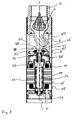
- Fig. 1 shows a sectional view of the upper end of a submersible pump.
- the lower end in which the electronics for controlling the pump is mounted, is not shown in the figure.
- the pump unit has at its upper end a connecting piece 2 with a non-return valve 4 arranged therein.
- a spiral housing 6, which surrounds the impeller 8, adjoins the inside of the pump assembly upstream.
- the impeller 8 is arranged at the axial end of the integral rotor shaft 10 of the electric motor 11 or its permanent magnet rotor 12.
- the impeller 8 is fixedly fixed to the rotor shaft 10, in particular in the axial direction X firmly connected.
- the permanent magnet rotor 12 runs inside a split tube 14 which is annular at its outer periphery surrounded by the stator 16.
- the stator 16 is formed in a known manner as a laminated core with coil windings.
- the stator 16 is hermetically sealed in total in a stator housing 18.
- the rotor shaft 10 is mounted in two radial bearings 20 in the radial direction. These radial bearings 20 are preferably self-centering, so that easy assembly and safe operation is ensured even at high speeds.
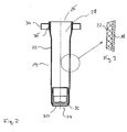
- the bottom member 30 may be manufactured separately and later inserted into the tubular member 22. As shown, a positive connection between bottom element 30 and tubular component 22 is produced in that the inwardly bent axial peripheral edge of the tubular component 22 engages in a circumferential groove 32 of the bottom element 30.
- a collar 34 is attached to the outer circumference of the tubular member 22.
- the collar 34 is made of metal, preferably stainless Stainless steel formed and annular, with its inner diameter is matched to the outer diameter of the tubular member 22 at the axial end 26.
- the ring of the collar 34 has a U-shaped cross-section, wherein the transverse leg faces the axial end 26.
- the inner wall 36 of the collar 34 abuts parallel to the peripheral wall of the tubular member 22 and is connected thereto.
- the gap tube 14 thus created is metallized.
- a thin metal layer 38 is applied to the outer surface of the can 14, as in Fig. 3 shown.
- the metal layer 38 covers the entire outer surface of the tubular member 22 and the bottom member 30 as well the collar 34.
- the transition regions between the collar 34 and the tubular member 22 and between the bottom member 30 and the tubular member 22 are covered by the metal layer 38.
- the metal layer 38 ensures that a hermetic seal of the can 14 and in particular the peripheral wall of the tubular member 22 is provided.
- This hermetic seal through the metal layer 38 causes fluid, which is located in the rotor chamber 28, can not penetrate through the split tube 14 into the interior of the stator housing 18, in which the stator 16 is arranged.
- the metallization or coating 38 allows the use of a plastic for the tubular member 22 and the bottom member 30, which is not diffusion-tight per se. So here the plastic can be selected purely according to the requirements of the stability of the can 14 and according to manufacturing considerations.
- split tube 14 has been described, which is provided on its outside with the metal layer 38.
- metal layer 38 it is also possible to provide the split tube 14 both on its outer side and on the inner surfaces of the inner space 28 with a metal layer by metallization.
- the metallic collar 34 serves to connect the split tube 14 with the remaining part of the stator housing 18. This can be done in particular by a weld 39 on the outer circumference of the metallic collar 34.
- the collar 34 thus provides the connection to other metallic components of which the stator housing 18 is formed, as in FIG Fig. 4 shown.
- the use of the can 14 of plastic, ie a non-metallic material without magnetic properties has the advantage that the split tube 14, the magnetic field between stator 16 and permanent magnet rotor 12 only slightly or not at all, whereby the efficiency of the electric motor 11 is increased.
- the diameter of the permanent magnet rotor 12 and the impeller 8 is kept small in order to minimize the friction in the system and thus the power loss as possible.
- the permanent magnet rotor 12 is equipped with particularly strong permanent magnets, for example neodynium magnets. In the example shown, the rotor diameter is 19 mm.
- the electric motor 11 shown is designed for very high speeds> 20,000, in particular between 25,000 and 30,000 rpm. Thus, with only one impeller 8 with a relatively small diameter, a sufficiently high flow rate can be achieved.
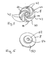
- the impeller 8 which in FIGS. 5 and 6 As an individual part is shown, to ensure a high wear resistance, made of carbide.
- the impeller blades 42 are formed on an axial side 40, which faces away from the electric motor 11 in the installed state.
- the impeller 8 is open, ie the impeller blades project from the axial side 40 of the impeller 8 and are not closed at their end faces 44 by a cover.
- the end faces or end edges 44 of the impeller blades 42 are ground and thus form a Axiallager- and sealing surface of the impeller 8.
- the end faces 44 are in the installed state of a counter-rotating disk 46, which surrounds the suction port 48 of the pump annular. Due to the fixed connection of the impeller 8 with the rotor shaft 10, the entire rotor 12 is supported via the impeller 8 in the axial direction on the counter-rotating disk 46. Ie. the end face of the counter-rotating disc 46, which faces the impeller 8, and the end faces 44 of the Impeller blades 42 form an axial sliding bearing.
- the end faces 44 of the impeller blades 42 are pressed against the mating disk 46 so that there is a particularly good seal between the impeller blades 42 and the counter-rotating disk 46.
- losses in the pump are minimized and the delivery rate of the pump unit is further increased, especially at the high engine speed described above.
- the impeller 8 assumes the a-xial workede seal against the mating disk 46 at the suction port 48 and at the same time the thrust bearing function, so that here the number of components and the friction occurring are minimized.
- the rear side 50 of the impeller 8 facing away from the impeller blades 42 has a further annular sealing surface 52, which annularly surrounds the opening 54 for receiving the rotor shaft.
- the sealing surface 52 bears against a seal 56, which surrounds the rotor shaft 10 fixedly and seals off the rotor chamber 28 in the interior of the can 14 for the pump chamber, in which the impeller 8 is arranged.
- This seal 56 is held by spring action on the sealing surface 52 in abutment.
- the seal 56 ensures that impurities in the fluid, which is conveyed by the impeller 8, do not penetrate into the rotor chamber 28 in the interior of the can 14 and there may lead to undesirable friction or damage.
- the counter-rotating disc 46 is also preferably made of hard metal or ceramic.
- the side facing away from the impeller 8 58 is formed spherically (in Fig. 1 not shown) and mounted in a spherical receptacle in the pump housing, so that the mating disk 46 can align automatically parallel to the impeller 8.
- This part of the counter-disc, which forms the back 58 may consist of a be formed material other than carbide or ceramic and with the part of the counter-rotating disc 46, which faces the impeller 8, be connected, for example by gluing.
- the impeller 8 is circumferentially surrounded by the spiral housing 6.
- the spiral housing 6 extends, starting from the peripheral region of the impeller 8, helically to the connecting piece 2, so that a flow deflection takes place in the axial direction. Ie. the flow, which exits in the radial / tangential direction on the outer circumference of the impeller 8, is first deflected by the volute 6 in a purely tangential direction or circumferential direction of the impeller 8 and then steered in the axial direction as lossless as possible due to the helical winding of the volute 6, so that the flow at the connecting piece 2 in the axial direction can escape from the pump unit.
- the spiral housing 6 is preferably also made of plastic as an injection molded part, the spiral housing 6 includes at its lower, the impeller 8 end facing also the also spherical receptacle for the mating disk 6 and centrally forms the suction port 48 of the pump, through which the fluid by rotation of Impeller 8 is sucked.
- the outer housing of the pump unit has in the region in which the spiral housing 6 is disposed in its outer peripheral wall inlet opening 62, through which the fluid enters from the outside, flows around the spiral housing 6 from the outside and then enters the suction mouth 48 ,
Landscapes
- Engineering & Computer Science (AREA)
- Mechanical Engineering (AREA)
- General Engineering & Computer Science (AREA)
- Power Engineering (AREA)
- Structures Of Non-Positive Displacement Pumps (AREA)
- Food Preservation Except Freezing, Refrigeration, And Drying (AREA)
- Motor Or Generator Frames (AREA)
- Acyclic And Carbocyclic Compounds In Medicinal Compositions (AREA)
Claims (23)
- Groupe motopompe comportant un moteur électrique de type humide (11) qui présente une gaine de moteur (14) fabriquée à partir d'un matériau non métallique (22), dans lequel le matériau non métallique (22) est muni d'au moins une couche supplémentaire (38) assurant l'étanchéité sous la forme d'une métallisation du matériau non métallique (22).
- Groupe motopompe selon la revendication 1, caractérisé en ce que la couche, au moins au nombre de une, est conçue sous forme d'un revêtement (38) au niveau de la surface périphérique interne et/ou externe du matériau non métallique (22).
- Groupe motopompe selon la revendication 1 ou 2, caractérisé en ce que la gaine de moteur (14) est fabriquée à partir d'une matière plastique, et de préférence d'une matière plastique renforcée à la fibre de verre.
- Groupe motopompe selon l'une des revendications précédentes, caractérisé en ce que la gaine de moteur (14) est fabriquée à partir d'un composant de forme tubulaire (22) et d'un élément de fond (30) qui obture l'élément de forme tubulaire (22) au niveau d'une première extrémité axiale (24).
- Groupe motopompe selon la revendication 4, caractérisé en ce que l'élément de fond (30) est coulé avec le composant de forme tubulaire (22).
- Groupe motopompe selon la revendication 4 ou 5, caractérisé en ce que le composant de forme tubulaire (22) et l'élément de fond (30) sont fabriqués à partir d'un matériau non métallique, de préférence à partir de matière plastique, et après le montage sont pourvus conjointement de la couche ou du revêtement supplémentaire (38).
- Groupe motopompe selon l'une des revendications précédentes, caractérisé en ce qu'au niveau d'une extrémité axiale (26) de la gaine de moteur (14) est formée au niveau de la périphérie extérieure une collerette (34), de préférence métallique, qui s'étend vers l'extérieur dans la direction radiale.
- Groupe motopompe selon la revendication 7, caractérisé en ce que la collerette (34) est reliée par engagement de forme et/ou de matière au matériau non métallique et est pourvue conjointement à celui-ci de la couche ou du revêtement supplémentaire (38).
- Groupe motopompe selon la revendication 7 ou 8, dans lequel une surface (36) de la collerette (34) est structurée avant la liaison avec le matériau non métallique de la gaine de moteur (14), de préférence par irradiation au laser.
- Groupe motopompe selon l'une des revendications précédentes, caractérisé en ce que le moteur électrique (11) présente un rotor à aimant permanent (12).
- Groupe motopompe selon l'une des revendications précédentes, caractérisé en ce qu'il est conçu sous forme d'un groupe motopompe à immersion.
- Groupe motopompe selon l'une des revendications précédentes, caractérisé en ce qu'une roue mobile (8) du groupe motopompe peut être entraînée par le moteur électrique (11) avec une vitesse de rotation maximum supérieure à 20 000 tours/minute, et en ce que la roue mobile (8) est rendue étanche axialement dans la zone de l'embouchure d'aspiration (48).
- Groupe motopompe selon la revendication 12, caractérisé en ce qu'au moins une face avant axiale (44) de la roue mobile (8) forme une surface de butée axiale qui sert de préférence simultanément de surface d'étanchéité axiale.
- Groupe motopompe selon la revendication 13, caractérisé en ce que la roue mobile (8) est exécutée de façon ouverte au niveau de son côté axial (40) au niveau duquel sont disposées les pales de la roue mobile (42), et en ce que les faces avant axiales (44) des pales de la roue mobile (42) forment une surface de butée axiale de la roue mobile (8).
- Groupe motopompe selon l'une des revendications précédentes, caractérisé en ce que la roue mobile (8) est fixée sur un arbre de rotor (10) dans la direction axiale (X).
- Groupe motopompe selon l'une des revendications précédentes, caractérisé en ce que la face avant axiale (50) de la roue mobile (8) orientée vers le moteur électrique (11) est conçue en tant que surface étanche pour rendre étanche l'espace de rotor (28) du moteur électrique (11).
- Groupe motopompe selon l'une des revendications précédentes, caractérisé en ce que la roue mobile (8) présente au moins une surface en métal dur ou en céramique et est fabriquée de préférence entièrement à partir de métal dur ou de céramique.
- Groupe motopompe selon l'une des revendications précédentes, caractérisé en ce qu'il présente un seul étage.
- Groupe motopompe selon l'une des revendications précédentes, caractérisé en ce qu'est prévu un disque à contre-rotation (46) orienté vers la roue mobile (8), qui repose contre un côté axial (44) de la roue mobile (8) de façon telle qu'il forme une surface de butée axiale (58).
- Groupe motopompe selon la revendication 19, caractérisé en ce que le disque à contre-rotation (46) présente au moins une surface en métal dur ou en matériau céramique.
- Groupe motopompe selon la revendication 19 ou 20, caractérisé en ce que le côté axial (58) du disque à contre-rotation (46) opposé à la roue mobile (8) est exécuté de façon sphérique.
- Groupe motopompe selon l'une des revendications précédentes, caractérisé en ce que la roue mobile (8) est entourée par un carter en spirale (6) ou un dispositif directeur.
- Groupe motopompe selon la revendication 22, caractérisé en ce que la roue mobile (8) est entourée par un carter en spirale (6) qui s'étend de façon hélicoïdale de façon telle que l'ouverture de sortie du carter en spirale est orientée dans la direction axiale (X) vers la roue mobile (8).
Priority Applications (7)
| Application Number | Priority Date | Filing Date | Title |
|---|---|---|---|
| AT05020867T ATE474366T1 (de) | 2005-09-24 | 2005-09-24 | Spaltrohr |
| EP05020867A EP1768233B1 (fr) | 2005-09-24 | 2005-09-24 | Tube d'entrefer |
| PL05020867T PL1768233T3 (pl) | 2005-09-24 | 2005-09-24 | Rura szczelinowa |
| DE502005009909T DE502005009909D1 (de) | 2005-09-24 | 2005-09-24 | Spaltrohr |
| CN2006800350494A CN101273509B (zh) | 2005-09-24 | 2006-09-20 | 泵装置 |
| PCT/EP2006/009114 WO2007033818A1 (fr) | 2005-09-24 | 2006-09-20 | Gaine |
| US12/067,871 US7839036B2 (en) | 2005-09-24 | 2006-09-20 | Can of wet-running electric motor and pump assembly |
Applications Claiming Priority (1)
| Application Number | Priority Date | Filing Date | Title |
|---|---|---|---|
| EP05020867A EP1768233B1 (fr) | 2005-09-24 | 2005-09-24 | Tube d'entrefer |
Publications (2)
| Publication Number | Publication Date |
|---|---|
| EP1768233A1 EP1768233A1 (fr) | 2007-03-28 |
| EP1768233B1 true EP1768233B1 (fr) | 2010-07-14 |
Family
ID=34993306
Family Applications (1)
| Application Number | Title | Priority Date | Filing Date |
|---|---|---|---|
| EP05020867A Ceased EP1768233B1 (fr) | 2005-09-24 | 2005-09-24 | Tube d'entrefer |
Country Status (7)
| Country | Link |
|---|---|
| US (1) | US7839036B2 (fr) |
| EP (1) | EP1768233B1 (fr) |
| CN (1) | CN101273509B (fr) |
| AT (1) | ATE474366T1 (fr) |
| DE (1) | DE502005009909D1 (fr) |
| PL (1) | PL1768233T3 (fr) |
| WO (1) | WO2007033818A1 (fr) |
Cited By (1)
| Publication number | Priority date | Publication date | Assignee | Title |
|---|---|---|---|---|
| DE102010054577A1 (de) * | 2010-12-15 | 2012-06-21 | Wilo Se | Kunststoffspalttopf für Kreiselpumpen |
Families Citing this family (13)
| Publication number | Priority date | Publication date | Assignee | Title |
|---|---|---|---|---|
| GB2449427B (en) | 2007-05-19 | 2012-09-26 | Converteam Technology Ltd | Control methods for the synchronisation and phase shift of the pulse width modulation (PWM) strategy of power converters |
| US8378533B2 (en) * | 2008-11-06 | 2013-02-19 | Nidec Corporation | Pump motor |
| DE102009033111A1 (de) * | 2009-07-15 | 2011-02-03 | Ksb Aktiengesellschaft | Spalttopf |
| EP2293417B1 (fr) * | 2009-09-05 | 2016-07-06 | Grundfos Management A/S | Pale de rotor |
| US8958291B2 (en) * | 2009-10-09 | 2015-02-17 | At&T Intellectual Property I, L.P. | Data routing in hybrid wireless communication networks |
| PL2626980T3 (pl) * | 2012-02-08 | 2015-04-30 | Grundfos Holding As | Agregat pompowy |
| EP2898591A2 (fr) * | 2012-10-25 | 2015-07-29 | Siemens Aktiengesellschaft | Couche barrière anti-diffusion pour gaines de moteurs |
| EP3032712B1 (fr) | 2014-12-12 | 2018-02-07 | Goodrich Control Systems | Moteur pour actionneur électro-hydraulique |
| DE102017102141A1 (de) * | 2017-02-03 | 2018-08-09 | Dr. Ing. H.C. F. Porsche Aktiengesellschaft | Verfahren zur Herstellung einer elektrischen Antriebsmaschine und elektrische Antriebsmaschine |
| EP3763943B1 (fr) | 2019-07-10 | 2024-09-04 | Grundfos Holding A/S | Procédé de fabrication d'une chemise d'entrefer |
| DE102019134334A1 (de) * | 2019-12-13 | 2021-06-17 | Wilo Se | Spaltrohr für eine Nassläuferpumpe und Verfahren zu dessen Herstellung |
| DE102021109789A1 (de) | 2021-04-19 | 2022-10-20 | Nidec Gpm Gmbh | Verfahren zum Herstellen eines dünnwandigen keramischen Bauteils, insbesondere eines Spaltrohres oder Spalttopfes, dünnwandiges keramisches Bauteil und Elektromotor aufweisend das dünnwandige keramische Bauteil sowie Nassläuferpumpe |
| US11984762B2 (en) * | 2021-10-04 | 2024-05-14 | Rolls-Royce Electrical Norway AS | Electric machine stator tube |
Family Cites Families (23)
| Publication number | Priority date | Publication date | Assignee | Title |
|---|---|---|---|---|
| US2766698A (en) * | 1950-07-18 | 1956-10-16 | J C Carter Company | Pump |
| AT309231B (de) * | 1971-05-27 | 1973-08-10 | Vortex Pumpen Ag | Kreiselpumpe zum Einbau in Rohrleitungssysteme |
| JPS5758783B2 (fr) * | 1973-02-22 | 1982-12-11 | Nippon Electric Co | |
| DE3636404A1 (de) * | 1986-10-25 | 1988-04-28 | Richter Chemie Technik Gmbh | Magnetkreiselpumpe |
| DE3708956C1 (de) * | 1987-03-19 | 1988-03-17 | Handtmann Albert Elteka Gmbh | Spaltringdichtung einer Kreiselpumpe |
| DE8816412U1 (de) * | 1988-03-09 | 1989-08-10 | Grundfos International A/S, Bjerringbro | Tauchpumpenaggregat |
| DE8905650U1 (de) * | 1988-06-03 | 1989-08-03 | Uranit GmbH, 5170 Jülich | Spalttopf für stopfbuchsenlose elektrische oder magnetische Antriebsaggregate |
| US5336064A (en) * | 1993-12-06 | 1994-08-09 | Westinghouse Electric Corporation | Electric motor driven pump |
| DE4342649C1 (de) * | 1993-12-14 | 1995-02-16 | Munsch Kunststoff Schweistechn | Magnetkreiselpumpe für aggressive Medien |
| JPH094587A (ja) * | 1995-06-21 | 1997-01-07 | Nikkiso Co Ltd | キャンドモータポンプのキャン構造 |
| US5660520A (en) * | 1996-01-25 | 1997-08-26 | Camco International Inc. | Downhole centrifugal pump |
| US5763973A (en) * | 1996-10-30 | 1998-06-09 | Imo Industries, Inc. | Composite barrier can for a magnetic coupling |
| US6254340B1 (en) * | 1997-04-23 | 2001-07-03 | Metaullics Systems Co., L.P. | Molten metal impeller |
| US6059533A (en) * | 1997-07-17 | 2000-05-09 | Alliedsignal Inc. | Damped blade having a single coating of vibration-damping material |
| US5923111A (en) * | 1997-11-10 | 1999-07-13 | Goulds Pumps, Incoporated | Modular permanent-magnet electric motor |
| US6293772B1 (en) * | 1998-10-29 | 2001-09-25 | Innovative Mag-Drive, Llc | Containment member for a magnetic-drive centrifugal pump |
| EP1120569B1 (fr) * | 1999-08-10 | 2015-07-29 | Iwaki Co., Ltd. | Pompe a aimant |
| US6799943B2 (en) * | 2000-01-26 | 2004-10-05 | The Gorman-Rupp Company | Centrifugal pump with multiple inlets |
| IT1315436B1 (it) * | 2000-04-27 | 2003-02-10 | Askoll Holding Srl | Struttura di motore elettrico a magneti permanenti per pompe dicircolazione di impianti di riscaldamento. |
| US7118354B2 (en) * | 2001-12-15 | 2006-10-10 | Fe Petro, Inc. | System and method for improving petroleum dispensing station dispensing flow rates and dispensing capacity |
| DE20211075U1 (de) * | 2002-07-22 | 2003-12-11 | Rpc Bramlage Gmbh | Behälterförmige Verpackungen |
| JP3838568B2 (ja) * | 2003-03-24 | 2006-10-25 | 株式会社前川製作所 | アンモニアキャンドモータ用積層キャンの構造及びその加工法 |
| US7455106B2 (en) * | 2005-09-07 | 2008-11-25 | Schlumberger Technology Corporation | Polymer protective coated polymeric components for oilfield applications |
-
2005
- 2005-09-24 DE DE502005009909T patent/DE502005009909D1/de not_active Expired - Lifetime
- 2005-09-24 AT AT05020867T patent/ATE474366T1/de not_active IP Right Cessation
- 2005-09-24 PL PL05020867T patent/PL1768233T3/pl unknown
- 2005-09-24 EP EP05020867A patent/EP1768233B1/fr not_active Ceased
-
2006
- 2006-09-20 US US12/067,871 patent/US7839036B2/en not_active Expired - Fee Related
- 2006-09-20 CN CN2006800350494A patent/CN101273509B/zh not_active Expired - Fee Related
- 2006-09-20 WO PCT/EP2006/009114 patent/WO2007033818A1/fr not_active Ceased
Cited By (1)
| Publication number | Priority date | Publication date | Assignee | Title |
|---|---|---|---|---|
| DE102010054577A1 (de) * | 2010-12-15 | 2012-06-21 | Wilo Se | Kunststoffspalttopf für Kreiselpumpen |
Also Published As
| Publication number | Publication date |
|---|---|
| ATE474366T1 (de) | 2010-07-15 |
| US20090026878A1 (en) | 2009-01-29 |
| WO2007033818A1 (fr) | 2007-03-29 |
| EP1768233A1 (fr) | 2007-03-28 |
| CN101273509B (zh) | 2013-01-09 |
| CN101273509A (zh) | 2008-09-24 |
| DE502005009909D1 (de) | 2010-08-26 |
| US7839036B2 (en) | 2010-11-23 |
| PL1768233T3 (pl) | 2010-12-31 |
Similar Documents
| Publication | Publication Date | Title |
|---|---|---|
| EP1767786B1 (fr) | Unité de pompe submersible | |
| EP1768233B1 (fr) | Tube d'entrefer | |
| DE102011079226B4 (de) | Flüssigkeitspumpe, insbesondere Wasserpumpe | |
| DE202005003689U1 (de) | Anordnung mit einem elekronisch kommutierten Außenläufermotor | |
| EP2072826A1 (fr) | Rotor pour un moteur à gaine | |
| DE102018125031A1 (de) | Pumpe, insbesondere für einen Flüssigkeitskreislauf in einem Fahrzeug | |
| EP2905472B1 (fr) | Pompe centrifuge de type humide | |
| DE102016202417A1 (de) | Kreiselpumpe | |
| EP1767787B2 (fr) | Unité de pompe submersible | |
| DE102011055599A1 (de) | Pumpe für einen Temperaturkreislauf in einem Fahrzeug | |
| WO2020074318A1 (fr) | Pompe conçue en particulier pour un circuit de liquide dans un véhicule | |
| DE102015106652A1 (de) | Elektrischer Verdichter für eine Verbrennungskraftmaschine | |
| DE3831457A1 (de) | Elektromotorisch angetriebene fluessigkeitspumpe | |
| EP2232080B1 (fr) | Rotor de pompe | |
| EP2002123B1 (fr) | Pompe a fluide | |
| EP1126180A2 (fr) | Roue d'une pompe centrifuge pour lave-vaisselle | |
| EP1811184B1 (fr) | Roue pour une unité de pompage et unité de pompage correspondante | |
| EP2818725A1 (fr) | Pompe centrifuge avec roue à aubes déplaçable axialement et obturable | |
| EP2342464B1 (fr) | Ventilateur à canal latéral, en particulier turbine secondaire pour un moteur à combustion interne | |
| DE102018201841B3 (de) | Pumpenlaufrad, Verfahren zur Herstellung eines Pumpenlaufrads und Pumpe mit dem Pumpenlaufrad | |
| EP3299627B1 (fr) | Pompe d'alimentation | |
| DE102011079225A1 (de) | Flüssigkeitspumpe, insbesondere Wasserpumpe | |
| EP3088746B1 (fr) | Pompe à vide | |
| EP1101944A2 (fr) | Pompe turbo-moléculaire | |
| EP4325061B1 (fr) | Pompe à vide turbomoléculaire |
Legal Events
| Date | Code | Title | Description |
|---|---|---|---|
| PUAI | Public reference made under article 153(3) epc to a published international application that has entered the european phase |
Free format text: ORIGINAL CODE: 0009012 |
|
| AK | Designated contracting states |
Kind code of ref document: A1 Designated state(s): AT BE BG CH CY CZ DE DK EE ES FI FR GB GR HU IE IS IT LI LT LU LV MC NL PL PT RO SE SI SK TR |
|
| AX | Request for extension of the european patent |
Extension state: AL BA HR MK YU |
|
| 17P | Request for examination filed |
Effective date: 20070919 |
|
| AKX | Designation fees paid |
Designated state(s): AT BE BG CH CY CZ DE DK EE ES FI FR GB GR HU IE IS IT LI LT LU LV MC NL PL PT RO SE SI SK TR |
|
| 17Q | First examination report despatched |
Effective date: 20080606 |
|
| GRAP | Despatch of communication of intention to grant a patent |
Free format text: ORIGINAL CODE: EPIDOSNIGR1 |
|
| RIN1 | Information on inventor provided before grant (corrected) |
Inventor name: BOLL, JENS VESTERGAARD Inventor name: BLOCH, CARSTEN Inventor name: LAURSEN, CECILIE HOJ Inventor name: HANSEN, JORN TOFTEGAARD |
|
| GRAS | Grant fee paid |
Free format text: ORIGINAL CODE: EPIDOSNIGR3 |
|
| GRAA | (expected) grant |
Free format text: ORIGINAL CODE: 0009210 |
|
| AK | Designated contracting states |
Kind code of ref document: B1 Designated state(s): AT BE BG CH CY CZ DE DK EE ES FI FR GB GR HU IE IS IT LI LT LU LV MC NL PL PT RO SE SI SK TR |
|
| REG | Reference to a national code |
Ref country code: GB Ref legal event code: FG4D Free format text: NOT ENGLISH |
|
| REG | Reference to a national code |
Ref country code: CH Ref legal event code: EP |
|
| REG | Reference to a national code |
Ref country code: IE Ref legal event code: FG4D |
|
| REF | Corresponds to: |
Ref document number: 502005009909 Country of ref document: DE Date of ref document: 20100826 Kind code of ref document: P |
|
| REG | Reference to a national code |
Ref country code: NL Ref legal event code: VDEP Effective date: 20100714 |
|
| LTIE | Lt: invalidation of european patent or patent extension |
Effective date: 20100714 |
|
| REG | Reference to a national code |
Ref country code: PL Ref legal event code: T3 |
|
| PG25 | Lapsed in a contracting state [announced via postgrant information from national office to epo] |
Ref country code: LT Free format text: LAPSE BECAUSE OF FAILURE TO SUBMIT A TRANSLATION OF THE DESCRIPTION OR TO PAY THE FEE WITHIN THE PRESCRIBED TIME-LIMIT Effective date: 20100714 Ref country code: FI Free format text: LAPSE BECAUSE OF FAILURE TO SUBMIT A TRANSLATION OF THE DESCRIPTION OR TO PAY THE FEE WITHIN THE PRESCRIBED TIME-LIMIT Effective date: 20100714 Ref country code: NL Free format text: LAPSE BECAUSE OF FAILURE TO SUBMIT A TRANSLATION OF THE DESCRIPTION OR TO PAY THE FEE WITHIN THE PRESCRIBED TIME-LIMIT Effective date: 20100714 |
|
| REG | Reference to a national code |
Ref country code: IE Ref legal event code: FD4D |
|
| PG25 | Lapsed in a contracting state [announced via postgrant information from national office to epo] |
Ref country code: SI Free format text: LAPSE BECAUSE OF FAILURE TO SUBMIT A TRANSLATION OF THE DESCRIPTION OR TO PAY THE FEE WITHIN THE PRESCRIBED TIME-LIMIT Effective date: 20100714 Ref country code: BG Free format text: LAPSE BECAUSE OF FAILURE TO SUBMIT A TRANSLATION OF THE DESCRIPTION OR TO PAY THE FEE WITHIN THE PRESCRIBED TIME-LIMIT Effective date: 20101014 Ref country code: CY Free format text: LAPSE BECAUSE OF FAILURE TO SUBMIT A TRANSLATION OF THE DESCRIPTION OR TO PAY THE FEE WITHIN THE PRESCRIBED TIME-LIMIT Effective date: 20100714 Ref country code: IS Free format text: LAPSE BECAUSE OF FAILURE TO SUBMIT A TRANSLATION OF THE DESCRIPTION OR TO PAY THE FEE WITHIN THE PRESCRIBED TIME-LIMIT Effective date: 20101114 Ref country code: PT Free format text: LAPSE BECAUSE OF FAILURE TO SUBMIT A TRANSLATION OF THE DESCRIPTION OR TO PAY THE FEE WITHIN THE PRESCRIBED TIME-LIMIT Effective date: 20101115 |
|
| BERE | Be: lapsed |
Owner name: GRUNDFOS MANAGEMENT A/S Effective date: 20100930 |
|
| PG25 | Lapsed in a contracting state [announced via postgrant information from national office to epo] |
Ref country code: SE Free format text: LAPSE BECAUSE OF FAILURE TO SUBMIT A TRANSLATION OF THE DESCRIPTION OR TO PAY THE FEE WITHIN THE PRESCRIBED TIME-LIMIT Effective date: 20100714 Ref country code: LV Free format text: LAPSE BECAUSE OF FAILURE TO SUBMIT A TRANSLATION OF THE DESCRIPTION OR TO PAY THE FEE WITHIN THE PRESCRIBED TIME-LIMIT Effective date: 20100714 Ref country code: GR Free format text: LAPSE BECAUSE OF FAILURE TO SUBMIT A TRANSLATION OF THE DESCRIPTION OR TO PAY THE FEE WITHIN THE PRESCRIBED TIME-LIMIT Effective date: 20101015 |
|
| PG25 | Lapsed in a contracting state [announced via postgrant information from national office to epo] |
Ref country code: DK Free format text: LAPSE BECAUSE OF FAILURE TO SUBMIT A TRANSLATION OF THE DESCRIPTION OR TO PAY THE FEE WITHIN THE PRESCRIBED TIME-LIMIT Effective date: 20100714 Ref country code: MC Free format text: LAPSE BECAUSE OF NON-PAYMENT OF DUE FEES Effective date: 20100930 Ref country code: IE Free format text: LAPSE BECAUSE OF FAILURE TO SUBMIT A TRANSLATION OF THE DESCRIPTION OR TO PAY THE FEE WITHIN THE PRESCRIBED TIME-LIMIT Effective date: 20100714 |
|
| REG | Reference to a national code |
Ref country code: CH Ref legal event code: PL |
|
| PLBE | No opposition filed within time limit |
Free format text: ORIGINAL CODE: 0009261 |
|
| STAA | Information on the status of an ep patent application or granted ep patent |
Free format text: STATUS: NO OPPOSITION FILED WITHIN TIME LIMIT |
|
| PG25 | Lapsed in a contracting state [announced via postgrant information from national office to epo] |
Ref country code: RO Free format text: LAPSE BECAUSE OF FAILURE TO SUBMIT A TRANSLATION OF THE DESCRIPTION OR TO PAY THE FEE WITHIN THE PRESCRIBED TIME-LIMIT Effective date: 20100714 Ref country code: CZ Free format text: LAPSE BECAUSE OF FAILURE TO SUBMIT A TRANSLATION OF THE DESCRIPTION OR TO PAY THE FEE WITHIN THE PRESCRIBED TIME-LIMIT Effective date: 20100714 Ref country code: SK Free format text: LAPSE BECAUSE OF FAILURE TO SUBMIT A TRANSLATION OF THE DESCRIPTION OR TO PAY THE FEE WITHIN THE PRESCRIBED TIME-LIMIT Effective date: 20100714 Ref country code: EE Free format text: LAPSE BECAUSE OF FAILURE TO SUBMIT A TRANSLATION OF THE DESCRIPTION OR TO PAY THE FEE WITHIN THE PRESCRIBED TIME-LIMIT Effective date: 20100714 |
|
| 26N | No opposition filed |
Effective date: 20110415 |
|
| PG25 | Lapsed in a contracting state [announced via postgrant information from national office to epo] |
Ref country code: ES Free format text: LAPSE BECAUSE OF FAILURE TO SUBMIT A TRANSLATION OF THE DESCRIPTION OR TO PAY THE FEE WITHIN THE PRESCRIBED TIME-LIMIT Effective date: 20101025 |
|
| REG | Reference to a national code |
Ref country code: DE Ref legal event code: R097 Ref document number: 502005009909 Country of ref document: DE Effective date: 20110415 |
|
| PG25 | Lapsed in a contracting state [announced via postgrant information from national office to epo] |
Ref country code: BE Free format text: LAPSE BECAUSE OF NON-PAYMENT OF DUE FEES Effective date: 20100930 Ref country code: CH Free format text: LAPSE BECAUSE OF NON-PAYMENT OF DUE FEES Effective date: 20100930 Ref country code: LI Free format text: LAPSE BECAUSE OF NON-PAYMENT OF DUE FEES Effective date: 20100930 |
|
| PG25 | Lapsed in a contracting state [announced via postgrant information from national office to epo] |
Ref country code: AT Free format text: LAPSE BECAUSE OF NON-PAYMENT OF DUE FEES Effective date: 20100924 |
|
| PG25 | Lapsed in a contracting state [announced via postgrant information from national office to epo] |
Ref country code: HU Free format text: LAPSE BECAUSE OF FAILURE TO SUBMIT A TRANSLATION OF THE DESCRIPTION OR TO PAY THE FEE WITHIN THE PRESCRIBED TIME-LIMIT Effective date: 20110115 Ref country code: LU Free format text: LAPSE BECAUSE OF NON-PAYMENT OF DUE FEES Effective date: 20100924 |
|
| PG25 | Lapsed in a contracting state [announced via postgrant information from national office to epo] |
Ref country code: TR Free format text: LAPSE BECAUSE OF FAILURE TO SUBMIT A TRANSLATION OF THE DESCRIPTION OR TO PAY THE FEE WITHIN THE PRESCRIBED TIME-LIMIT Effective date: 20100714 |
|
| REG | Reference to a national code |
Ref country code: FR Ref legal event code: PLFP Year of fee payment: 12 |
|
| REG | Reference to a national code |
Ref country code: FR Ref legal event code: PLFP Year of fee payment: 13 |
|
| REG | Reference to a national code |
Ref country code: FR Ref legal event code: PLFP Year of fee payment: 14 |
|
| PGFP | Annual fee paid to national office [announced via postgrant information from national office to epo] |
Ref country code: FR Payment date: 20210927 Year of fee payment: 17 Ref country code: IT Payment date: 20210930 Year of fee payment: 17 |
|
| PGFP | Annual fee paid to national office [announced via postgrant information from national office to epo] |
Ref country code: PL Payment date: 20210915 Year of fee payment: 17 Ref country code: DE Payment date: 20210923 Year of fee payment: 17 Ref country code: GB Payment date: 20210923 Year of fee payment: 17 |
|
| REG | Reference to a national code |
Ref country code: DE Ref legal event code: R119 Ref document number: 502005009909 Country of ref document: DE |
|
| GBPC | Gb: european patent ceased through non-payment of renewal fee |
Effective date: 20220924 |
|
| PG25 | Lapsed in a contracting state [announced via postgrant information from national office to epo] |
Ref country code: FR Free format text: LAPSE BECAUSE OF NON-PAYMENT OF DUE FEES Effective date: 20220930 Ref country code: DE Free format text: LAPSE BECAUSE OF NON-PAYMENT OF DUE FEES Effective date: 20230401 |
|
| PG25 | Lapsed in a contracting state [announced via postgrant information from national office to epo] |
Ref country code: IT Free format text: LAPSE BECAUSE OF NON-PAYMENT OF DUE FEES Effective date: 20220924 Ref country code: GB Free format text: LAPSE BECAUSE OF NON-PAYMENT OF DUE FEES Effective date: 20220924 |
|
| PG25 | Lapsed in a contracting state [announced via postgrant information from national office to epo] |
Ref country code: PL Free format text: LAPSE BECAUSE OF NON-PAYMENT OF DUE FEES Effective date: 20220924 |