EP1768448A2 - Suspension moulée avec des conducteurs intégrés - Google Patents
Suspension moulée avec des conducteurs intégrés Download PDFInfo
- Publication number
- EP1768448A2 EP1768448A2 EP06019751A EP06019751A EP1768448A2 EP 1768448 A2 EP1768448 A2 EP 1768448A2 EP 06019751 A EP06019751 A EP 06019751A EP 06019751 A EP06019751 A EP 06019751A EP 1768448 A2 EP1768448 A2 EP 1768448A2
- Authority
- EP
- European Patent Office
- Prior art keywords
- suspension member
- electro
- piston
- diaphragm
- acoustic transducer
- Prior art date
- Legal status (The legal status is an assumption and is not a legal conclusion. Google has not performed a legal analysis and makes no representation as to the accuracy of the status listed.)
- Withdrawn
Links
Images


Classifications
-
- H—ELECTRICITY
- H04—ELECTRIC COMMUNICATION TECHNIQUE
- H04R—LOUDSPEAKERS, MICROPHONES, GRAMOPHONE PICK-UPS OR LIKE ACOUSTIC ELECTROMECHANICAL TRANSDUCERS; ELECTRIC HEARING AIDS; PUBLIC ADDRESS SYSTEMS
- H04R7/00—Diaphragms for electromechanical transducers; Cones
- H04R7/16—Mounting or tensioning of diaphragms or cones
- H04R7/18—Mounting or tensioning of diaphragms or cones at the periphery
- H04R7/20—Securing diaphragm or cone resiliently to support by flexible material, springs, cords, or strands
-
- H—ELECTRICITY
- H04—ELECTRIC COMMUNICATION TECHNIQUE
- H04R—LOUDSPEAKERS, MICROPHONES, GRAMOPHONE PICK-UPS OR LIKE ACOUSTIC ELECTROMECHANICAL TRANSDUCERS; ELECTRIC HEARING AIDS; PUBLIC ADDRESS SYSTEMS
- H04R1/00—Details of transducers, loudspeakers or microphones
- H04R1/06—Arranging circuit leads; Relieving strain on circuit leads
-
- H—ELECTRICITY
- H04—ELECTRIC COMMUNICATION TECHNIQUE
- H04R—LOUDSPEAKERS, MICROPHONES, GRAMOPHONE PICK-UPS OR LIKE ACOUSTIC ELECTROMECHANICAL TRANSDUCERS; ELECTRIC HEARING AIDS; PUBLIC ADDRESS SYSTEMS
- H04R7/00—Diaphragms for electromechanical transducers; Cones
- H04R7/02—Diaphragms for electromechanical transducers; Cones characterised by the construction
-
- H—ELECTRICITY
- H04—ELECTRIC COMMUNICATION TECHNIQUE
- H04R—LOUDSPEAKERS, MICROPHONES, GRAMOPHONE PICK-UPS OR LIKE ACOUSTIC ELECTROMECHANICAL TRANSDUCERS; ELECTRIC HEARING AIDS; PUBLIC ADDRESS SYSTEMS
- H04R7/00—Diaphragms for electromechanical transducers; Cones
- H04R7/16—Mounting or tensioning of diaphragms or cones
- H04R7/18—Mounting or tensioning of diaphragms or cones at the periphery
-
- H—ELECTRICITY
- H04—ELECTRIC COMMUNICATION TECHNIQUE
- H04R—LOUDSPEAKERS, MICROPHONES, GRAMOPHONE PICK-UPS OR LIKE ACOUSTIC ELECTROMECHANICAL TRANSDUCERS; ELECTRIC HEARING AIDS; PUBLIC ADDRESS SYSTEMS
- H04R9/00—Transducers of moving-coil, moving-strip, or moving-wire type
- H04R9/02—Details
-
- H—ELECTRICITY
- H04—ELECTRIC COMMUNICATION TECHNIQUE
- H04R—LOUDSPEAKERS, MICROPHONES, GRAMOPHONE PICK-UPS OR LIKE ACOUSTIC ELECTROMECHANICAL TRANSDUCERS; ELECTRIC HEARING AIDS; PUBLIC ADDRESS SYSTEMS
- H04R1/00—Details of transducers, loudspeakers or microphones
- H04R1/10—Earpieces; Attachments therefor ; Earphones; Monophonic headphones
- H04R1/1016—Earpieces of the intra-aural type
-
- H—ELECTRICITY
- H04—ELECTRIC COMMUNICATION TECHNIQUE
- H04R—LOUDSPEAKERS, MICROPHONES, GRAMOPHONE PICK-UPS OR LIKE ACOUSTIC ELECTROMECHANICAL TRANSDUCERS; ELECTRIC HEARING AIDS; PUBLIC ADDRESS SYSTEMS
- H04R2231/00—Details of apparatus or processes specially adapted for the manufacture of transducers or diaphragms therefor covered by H04R31/00, not provided for in its subgroups
- H04R2231/003—Manufacturing aspects of the outer suspension of loudspeaker or microphone diaphragms or of their connecting aspects to said diaphragms
-
- H—ELECTRICITY
- H04—ELECTRIC COMMUNICATION TECHNIQUE
- H04R—LOUDSPEAKERS, MICROPHONES, GRAMOPHONE PICK-UPS OR LIKE ACOUSTIC ELECTROMECHANICAL TRANSDUCERS; ELECTRIC HEARING AIDS; PUBLIC ADDRESS SYSTEMS
- H04R2307/00—Details of diaphragms or cones for electromechanical transducers, their suspension or their manufacture covered by H04R7/00 or H04R31/003, not provided for in any of its subgroups
- H04R2307/204—Material aspects of the outer suspension of loudspeaker diaphragms
-
- H—ELECTRICITY
- H04—ELECTRIC COMMUNICATION TECHNIQUE
- H04R—LOUDSPEAKERS, MICROPHONES, GRAMOPHONE PICK-UPS OR LIKE ACOUSTIC ELECTROMECHANICAL TRANSDUCERS; ELECTRIC HEARING AIDS; PUBLIC ADDRESS SYSTEMS
- H04R2307/00—Details of diaphragms or cones for electromechanical transducers, their suspension or their manufacture covered by H04R7/00 or H04R31/003, not provided for in any of its subgroups
- H04R2307/207—Shape aspects of the outer suspension of loudspeaker diaphragms
-
- H—ELECTRICITY
- H04—ELECTRIC COMMUNICATION TECHNIQUE
- H04R—LOUDSPEAKERS, MICROPHONES, GRAMOPHONE PICK-UPS OR LIKE ACOUSTIC ELECTROMECHANICAL TRANSDUCERS; ELECTRIC HEARING AIDS; PUBLIC ADDRESS SYSTEMS
- H04R2499/00—Aspects covered by H04R or H04S not otherwise provided for in their subgroups
- H04R2499/10—General applications
- H04R2499/11—Transducers incorporated or for use in hand-held devices, e.g. mobile phones, PDA's, camera's
-
- H—ELECTRICITY
- H04—ELECTRIC COMMUNICATION TECHNIQUE
- H04R—LOUDSPEAKERS, MICROPHONES, GRAMOPHONE PICK-UPS OR LIKE ACOUSTIC ELECTROMECHANICAL TRANSDUCERS; ELECTRIC HEARING AIDS; PUBLIC ADDRESS SYSTEMS
- H04R25/00—Electric hearing aids
-
- H—ELECTRICITY
- H04—ELECTRIC COMMUNICATION TECHNIQUE
- H04R—LOUDSPEAKERS, MICROPHONES, GRAMOPHONE PICK-UPS OR LIKE ACOUSTIC ELECTROMECHANICAL TRANSDUCERS; ELECTRIC HEARING AIDS; PUBLIC ADDRESS SYSTEMS
- H04R31/00—Apparatus or processes specially adapted for the manufacture of transducers or diaphragms therefor
Definitions
- the present invention relates to a moulded surround with integrated lead-out wires.
- the present invention relates to moulded surround of silicone, rubber or any other soft material.
- the present invention relates to a custom designed diaphragm being constituted by a soft surround and a significantly stiffer piston of, for example, kapton, aluminium, nylon or flex print.
- PCT Publication No. WO 2005/055657 relates, in general, to methods for manufacturing vibrators for electro-acoustic transducers and, more particularly, to a method of manufacturing a vibrator for an electro-acoustic transducer, such as a miniature loudspeaker to be used in mobile communication terminals, in which an edge support is integrally formed around a circumferential border of a diaphragm through silicone injection moulding.
- PCT Publication No. WO 2005/055657 also relates to a moulding apparatus in which edges and borders of a diaphragm may be integrally formed.
- edge supports and diaphragms suggested in PCT Publication No. WO 2005/055657 that electrical leads to for example electrical coils attached to the piston are vulnerable due to movements of the diaphragm.
- an electro-acoustic transducer comprising
- the electro-mechanical motor may be operated in two modes of operation.
- a first mode of operation the electro-mechanical motor may be adapted to generate an electrical output signal in response to displacements of the diaphragm due to pressure variations, such as audible sound pressures, in the environment surrounding the electro-acoustic transducer.
- the electro-acoustic transducer is operated as a microphone, preferably a miniature microphone.
- the electro-mechanical motor is adapted to receive an incoming electrical signal and, in response to this, generate an audible acoustical signal by displacing the diaphragm in response to the electrical input signal.
- the electro-acoustic transducer is operated as a speaker, preferably a miniature speaker.
- the electro-mechanical motor may in general be implemented as a moving coil arrangement or a moving magnet arrangement.
- the electro-mechanical motor may comprise a magnetic circuit adapted to generate a magnetic flux in an air gap.
- an electrically conducting voice coil comprising first and second end portions may be provided.
- the voice coil may be operatively connected to the diaphragm and, at least partly, positioned in the air gap.
- the first and second end portions of the voice coil are preferably electrically connected to first and second electrically conducting elements, respectively.
- the electro-mechanical motor may comprise means for generating a magnetic field in response to an electrical input signal.
- a mechanical drive member operatively connected to the diaphragm may be provided, said mechanical drive member being movable in response to the electrical input signal.
- the mechanical drive member causes a displacement of the diaphragm.
- This type of motor is often referred to as a moving armature arrangement.
- the inner portion of the suspension member may comprise an inner edge attached to an associated outer edge of the piston.
- the inner edge of the suspension member forms a through-going opening prior to the piston being attached to the suspension member.
- the inner portion of the suspension member may comprise a supporting surface attached to an associated surface portion of the piston.
- the supporting surface of the suspension member may comprise an essentially plane surface portion.
- the suspension member comprises a supporting surface to which the piston may be glued, welded or by other means attached to.
- the at least one electrically conducting element may be at least partly embedded into the flexible member.
- the flexible member may be manufactured of a material selected from the group consisting of: silicone, rubber or any combination thereof.
- the present invention relates to a suspension member for a diaphragm, the suspension member comprising:
- the suspension member is the soft part of a diaphragm whereas the piston, which is surrounded by and suspended in the surround, constitutes a significantly stiffer part of the diaphragm.
- the surround is adapted to be a flexible and deformable element of the diaphragm
- the piston is adapted to essentially maintain its shape during displacements.
- the piston is adapted to perform translational movements while essentially maintaining its shape as long as the displacements are performed within an intended frequency operating range, such as within a frequency range from 20 Hz to 20 kHz.
- the intended frequency operating range may also be significantly narrower.
- the substantially stationary portion of the associated electro-acoustic transducer may be the housing of the electro-acoustic transducer or it may, alternatively, be a part of a magnetic circuit driving the diaphragm.
- the surround material may be chosen independently of the piston material.
- This advantage provides the flexibility that the surround material may be chosen among soft materials whereas the piston material may be chosen among significantly stiffer materials.
- a combined surround and piston may be custom designed to have specific properties such as a diaphragm optimized to have a very low resonance frequency and a flat frequency response.
- a stiffer piston material will cause the diaphragm to have a very large bandwidth.
- the at least one conducting element may be adapted to transport signals between one or more circuits arranged on the substantially stationary portion side of the suspension member and one or more circuits arranged on the piston.
- signals may be power supply signals applied across the surround, data signals, such as clock signals or other synchronising signals, provided to or from electronic circuits positioned either on the piston or elsewhere in an associated electro-acoustic transducer housing, signals for driving one or more moving coils arranged on or integrated with the piston etc.
- the inner portion of the suspension member may comprise an inner edge adapted to be attached to an associated outer edge of the piston.
- the inner edge of the suspension member forms a through-going opening prior to the piston being attached to the suspension member.
- the inner portion of the suspension member may comprise a supporting surface adapted to be attached to an associated surface portion of the piston.
- the supporting surface of the suspension member may comprise an essentially plane surface portion.
- the suspension member comprises a supporting surface to which the piston may be glued, welded or by other means attached to.
- the at least one electrically conducting element may be at least partly embedded into the flexible member having a first free end accessible at the inner portion and a second free end accessible at the outer portion of the suspension member.
- the at least one electrically conducting element takes the form of a thin electrically conducting wire fully, except for the first and second free ends, embedded into the surround.
- the number of wires embedded into the surround can be adjusted depending on the specific application of the diaphragm. Thus, the number of wires may in principle be chosen arbitrary and the surround may thus comprise 1, 2, 4, 6, 10 or even a higher number of wires embedded into the surround.
- the surround itself may comprise a material selected from the group consisting of: silicone, rubber or any combination thereof. However, any soft material with the appropriate mechanical properties may in principle be used.
- the surround may in principle take any shape.
- the surround may take a substantially circular shape, a substantially oval shape or a substantially rectangular shape. Combinations of these shapes are also applicable.
- the present invention relates to a diaphragm for an electro-acoustic transducer, the diaphragm comprising a suspension member and a piston.
- the suspension member may be in accordance with the second aspect of the present invention.
- the piston may be secured to the inner portion of the suspension member.
- a diaphragm may be defined as an essentially stiff piston portion and a flexible surround surrounding and suspending the piston portion.
- the piston may comprise a material selected from a group consisting of: kapton, aluminium, polymer, such as nylon, or other materials having similar mechanical properties in terms of Young's modulus.
- the piston may be formed by a flex print, optionally with integrated coils arranged thereon.
- the present invention relates to a portable communication device comprising at least one electro-acoustic transducer according to the first aspect of the present invention, said portable communication device being selected from the group consisting of: cellular phones, PDAs, game consoles, In the Ear Monitors (IEMs), hearing prosthesis's and portable computers.
- a portable communication device comprising at least one electro-acoustic transducer according to the first aspect of the present invention, said portable communication device being selected from the group consisting of: cellular phones, PDAs, game consoles, In the Ear Monitors (IEMs), hearing prosthesis's and portable computers.
- IEMs Ear Monitors
- the present invention relates to a method for manufacturing a suspension member according to the second aspect of the present invention, the method comprising the steps of:
- the method may further comprise the step of injection moulding one or more suspension members by providing an injection mouldable material into the one or more insert moulds.
- the injection mouldable material may be selected from the group consisting of: silicone, rubber, or any combination thereof.
- the method may further comprise the step of disconnecting a lead-out wire or lead-out wires between neighbouring insert moulds.
- integrated lead-out wires may easily be embedded into a plurality of surrounds by positioning an unbroken lead-out wire across a plurality of injection moulds and injection moulding one or more surrounds by providing an injection mouldable material into the one or more insert moulds. After the injection moulding process the surrounds are separated by cutting the wires which interconnects them.
- the present invention relates to a moulded surround with at least one integrated lead-out wire.
- the lead-out wire is integrated for provided an electrical connection across the moulded surround.
- the moulded surround according to the present invention is depicted in Fig. 1.
- the surround has an inner edge 1 and an outer edge 2.
- the inner edge 1 is adapted for being attached to a piston part (not shown) whereas the outer edge 2 is adapted for being attached to a stiff portion of a magnetic circuit.
- the piston can be attached to the moulded surround by means such as, for example, gluing, heating or ultrasound-based welding.
- Two integrated lead-out wires 3, 4 are depicted in Fig. 1.
- Each of these lead-out wires has an inner end 5, 6 and an outer end 7, 8.
- the inner ends 5, 6 are adapted to be electrical connected to electrical elements/circuits arranged on a piston attached to the inner edge 1.
- Such electrical elements/circuit can be wounded coils, such as voice coils or other moving coils, ASICs or other kinds of electronic circuits.
- the number of lead-out wires can differ from the two lead-out wires depicted in Fig. 1.
- lead-out wires for power supply, clock signals, data signals, etc. may be provided in order to transport electrical signals across the moulded surround.
- the moulded surround itself is made of a soft material, such as silicone, rubber or a similar soft material, and this material can be chosen independently of the piston material.
- the piston to be attached to the surround is typically made of a stiffer material, such as kapton, aluminium, nylon, flex print etc.
- the technique according to the present invention allows integration of lead-out wires into the surround so that the integrated lead-out wires are ready for contacting to, for example, a voice coil which, at a later stage, will be attached to the piston area.
- the lead-out wire By feeding the lead-out wire into the insert mould, the lead-out wire can be moulded into the surround and thereby form an integrated part of it. This is advantageous because the lead-out wires in miniature electro-acoustic transducers are a weak spot in the construction and tend to break under severe power and displacement conditions. By integrating the lead-out wires into the surround, the lead-out wires are protected and controlled in their movement which will result in an optimal reliability.
- Fig. 2 shows a cross-sectional view of a moulded surround with two integrated lead-out wires.
- the number of lead-out wires can differ from two dependent on the specific applications of the surround.
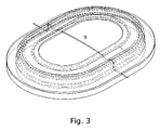
- a moulded surround with a through-going lead-out wire 9 is depicted.
- This through-going lead-out wire is a result of an advantageous fabrication technique where a series of injection moulds are positioned next to each other and where a single wire is positioned across all moulds.
- a series of moulded surrounds with a through-going integrated lead-out wire or lead-out wires can be manufactured.
- the through-going lead-out wire 9 shown in Fig. 3 needs to be cut so that the free wire ends can be connected to for example a voice coil attached to the piston.
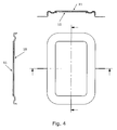
- Fig. 4 shows cross-sectional views of an alternative embodiment of the present invention.
- a supporting surface 10 is moulded together with the surround.
- the supporting surface 10 is moulded in the same process where also the surround itself is moulded.
- the supporting surface 10 forms a supporting surface for mounting a piston 11 so that a better support for this piston is achieved.
- the piston can be attached to the support 10 (or to the inner edge 1 of Fig. 1) by means such as, for example, gluing, heating or ultrasound-based welding.
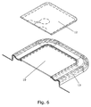
- Figs. 5 and 6 show how the piston 12 is mounted on the supporting surface 10 of the surround 13. Again, the piston can be attached to the surround by means such as, for example, gluing, heating or ultrasound-based welding.
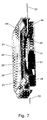
- Fig. 7 shows a cross-sectional view of an electro-acoustic transducer according to the present invention.
- the electro-acoustic transducer comprises a motor comprising a yoke 14, a centre magnet 15, an annular magnet 16, a centre pole piece 17, an outer pole piece 18 and a voice coil 19 positioned in an air gap between the centre pole piece 17 and the outer pole piece 18.
- the voice coil 19 is attached to the piston 20, the latter forming part of a displaceable diaphragm also comprising the surround 21 having at least two integrated lead-out wires 22, 23 integrated therein.
- a cover 24 having one or more acoustical outlets 25 arranged therein protects the diaphragm.
- the piston 20 of the diaphragm depicted in Fig. 7 carries an electronic device 26 in form of the coil arranged on the upper surface of the piston 20.
- This coil may be adapted for establishing a coupling to a T-coil of an external hearing aid.
- the lead-outs 22, 23 are adapted to allow electrical signals to be transported across the surround 21 to the planar coil 26 and the voice coil 19.
- an ASIC is arranged on the piston 20 as well additional lead-outs are required in order to transport signals to and from said ASIC.
- the moulded surrounds depicted in Figs. 1-7 are all illustrated as being oval or rectangular in shape. However, the moulded surround may, in principle, take any shape such as circular, elliptical, quadratic, or any other shape.
Landscapes
- Engineering & Computer Science (AREA)
- Physics & Mathematics (AREA)
- Acoustics & Sound (AREA)
- Signal Processing (AREA)
- Multimedia (AREA)
- Audible-Bandwidth Dynamoelectric Transducers Other Than Pickups (AREA)
Applications Claiming Priority (1)
| Application Number | Priority Date | Filing Date | Title |
|---|---|---|---|
| US71904305P | 2005-09-21 | 2005-09-21 |
Publications (2)
| Publication Number | Publication Date |
|---|---|
| EP1768448A2 true EP1768448A2 (fr) | 2007-03-28 |
| EP1768448A3 EP1768448A3 (fr) | 2007-07-04 |
Family
ID=37507678
Family Applications (1)
| Application Number | Title | Priority Date | Filing Date |
|---|---|---|---|
| EP06019751A Withdrawn EP1768448A3 (fr) | 2005-09-21 | 2006-09-21 | Suspension moulée avec des conducteurs intégrés |
Country Status (4)
| Country | Link |
|---|---|
| US (1) | US20070071274A1 (fr) |
| EP (1) | EP1768448A3 (fr) |
| KR (1) | KR20070033293A (fr) |
| CN (1) | CN101026899A (fr) |
Cited By (4)
| Publication number | Priority date | Publication date | Assignee | Title |
|---|---|---|---|---|
| EP2028876A1 (fr) * | 2007-08-21 | 2009-02-25 | Harman Becker Automotive Systems GmbH | Suspension de centrage de haut-parleur |
| EP2317776A3 (fr) * | 2009-09-25 | 2012-02-15 | Hosiden Corporation | Amortisseur de haut-parleur et haut-parleur équipé de celui-ci |
| EP3288288A4 (fr) * | 2015-04-23 | 2018-11-14 | Goertek Inc. | Diaphragme de gel de silice, module récepteur et procédé de traitement de diaphragme de gel de silice |
| EP3288287A4 (fr) * | 2015-04-23 | 2018-11-21 | Goertek Inc. | Diaphragme de gel de silice, module de haut-parleur, et procédé de retraitement de diaphragme de gel de silice |
Families Citing this family (15)
| Publication number | Priority date | Publication date | Assignee | Title |
|---|---|---|---|---|
| CN1933678A (zh) * | 2006-09-30 | 2007-03-21 | 宁波升亚电子有限公司 | 电磁振动器及其制造方法 |
| US8295538B2 (en) * | 2008-08-22 | 2012-10-23 | Harman Becker Automotive Systems Gmbh | Loudspeaker spider |
| US8110951B2 (en) * | 2008-12-17 | 2012-02-07 | Hsin Min Huang | Electromagnetic vibrator and producing method thereof |
| CN101820567A (zh) * | 2009-02-27 | 2010-09-01 | 宁波升亚电子有限公司 | 扬声器及其制造方法 |
| EP2624595A4 (fr) * | 2011-05-19 | 2015-07-01 | Tang Band Ind Co Ltd | Dispositif à plaque vibrante d'un vibreur électromagnétique et son procédé de fabrication |
| US8718317B2 (en) * | 2011-05-19 | 2014-05-06 | Zonghan Wu | Moving-magnet electromagnetic device with planar coil |
| CN202873044U (zh) * | 2012-09-14 | 2013-04-10 | 瑞声光电科技(常州)有限公司 | 一种定心支片及应用所述定心支片的扬声器 |
| US9788122B2 (en) * | 2012-12-26 | 2017-10-10 | Xin Min HUANG | Vibrating panel device for electromagnetic vibrator and manufacture method thereof |
| US9363593B2 (en) * | 2014-05-01 | 2016-06-07 | Bose Corporation | Transducer suspension elements with built-in tinsel wire |
| US9712921B2 (en) | 2014-08-25 | 2017-07-18 | Apple Inc. | High aspect ratio microspeaker having a two-plane suspension |
| CN204929239U (zh) * | 2015-08-10 | 2015-12-30 | 常州美欧电子有限公司 | 扬声器 |
| CN204929240U (zh) * | 2015-08-10 | 2015-12-30 | 常州美欧电子有限公司 | 扬声器 |
| US10321235B2 (en) | 2016-09-23 | 2019-06-11 | Apple Inc. | Transducer having a conductive suspension member |
| US10555085B2 (en) | 2017-06-16 | 2020-02-04 | Apple Inc. | High aspect ratio moving coil transducer |
| US10187730B1 (en) * | 2018-08-10 | 2019-01-22 | AAC Technologies Pte. Ltd. | Sound generating device |
Citations (1)
| Publication number | Priority date | Publication date | Assignee | Title |
|---|---|---|---|---|
| FR2561848A1 (fr) * | 1984-03-20 | 1985-09-27 | Pariente Francis | Branchement interne de la bobine mobile d'un haut-parleur par liaisons electriques situees uniquement sur la membrane et eventuellement sur sa collerette souple |
Family Cites Families (11)
| Publication number | Priority date | Publication date | Assignee | Title |
|---|---|---|---|---|
| US3351719A (en) * | 1964-02-05 | 1967-11-07 | Electronic Res Associates Inc | Loudspeaker assembly |
| JPH01268400A (ja) * | 1988-04-20 | 1989-10-26 | Matsushita Electric Ind Co Ltd | スピーカ |
| JPH02101897A (ja) * | 1988-10-11 | 1990-04-13 | Pioneer Electron Corp | スピーカ用振動板 |
| JP3331908B2 (ja) * | 1997-05-22 | 2002-10-07 | 株式会社ケンウッド | スピーカ用サスペンション装置の製造方法及びスピーカ用サスペンション製造用金型 |
| JP3893004B2 (ja) * | 1999-12-28 | 2007-03-14 | パイオニア株式会社 | スピーカ用導電ダンパーの製造装置 |
| CN1620839A (zh) * | 2002-01-25 | 2005-05-25 | 桑尼昂霍森斯公司 | 具有集成线圈的柔性振动膜 |
| WO2003101149A1 (fr) * | 2002-05-20 | 2003-12-04 | Sahyoun Joseph Y | Anneau de centrage audio comportant des conducteurs electriques acheminant des signaux de bobine acoustique, et procede associe |
| US6700988B2 (en) * | 2002-07-15 | 2004-03-02 | George K. Wu | Speaker spider with integral lead wire arrangement and manufacturing method thereof |
| WO2005055657A1 (fr) * | 2003-12-08 | 2005-06-16 | Bujeon Components., Ltd. | Procede et appareil de production de vibreur pour transducteurs electroacoustiques, vibreur produit selon ce procede et transducteur electroacoustique dote du vibreur |
| US7346183B2 (en) * | 2005-01-19 | 2008-03-18 | Hiroshi Ohara | Spider with lead wires sandwiched |
| US20060251285A1 (en) * | 2005-05-05 | 2006-11-09 | Mrs. Yen-Chen Chan | [surge-proof damper] |
-
2006
- 2006-09-21 EP EP06019751A patent/EP1768448A3/fr not_active Withdrawn
- 2006-09-21 CN CNA2006100644076A patent/CN101026899A/zh active Pending
- 2006-09-21 KR KR1020060091935A patent/KR20070033293A/ko not_active Withdrawn
- 2006-09-21 US US11/525,005 patent/US20070071274A1/en not_active Abandoned
Patent Citations (1)
| Publication number | Priority date | Publication date | Assignee | Title |
|---|---|---|---|---|
| FR2561848A1 (fr) * | 1984-03-20 | 1985-09-27 | Pariente Francis | Branchement interne de la bobine mobile d'un haut-parleur par liaisons electriques situees uniquement sur la membrane et eventuellement sur sa collerette souple |
Cited By (5)
| Publication number | Priority date | Publication date | Assignee | Title |
|---|---|---|---|---|
| EP2028876A1 (fr) * | 2007-08-21 | 2009-02-25 | Harman Becker Automotive Systems GmbH | Suspension de centrage de haut-parleur |
| EP2317776A3 (fr) * | 2009-09-25 | 2012-02-15 | Hosiden Corporation | Amortisseur de haut-parleur et haut-parleur équipé de celui-ci |
| EP3288288A4 (fr) * | 2015-04-23 | 2018-11-14 | Goertek Inc. | Diaphragme de gel de silice, module récepteur et procédé de traitement de diaphragme de gel de silice |
| EP3288287A4 (fr) * | 2015-04-23 | 2018-11-21 | Goertek Inc. | Diaphragme de gel de silice, module de haut-parleur, et procédé de retraitement de diaphragme de gel de silice |
| US10375462B2 (en) | 2015-04-23 | 2019-08-06 | Goertek Inc. | Silica gel diaphragm, receiver module, and method for processing silica gel diaphragm |
Also Published As
| Publication number | Publication date |
|---|---|
| US20070071274A1 (en) | 2007-03-29 |
| CN101026899A (zh) | 2007-08-29 |
| EP1768448A3 (fr) | 2007-07-04 |
| KR20070033293A (ko) | 2007-03-26 |
Similar Documents
| Publication | Publication Date | Title |
|---|---|---|
| EP1768448A2 (fr) | Suspension moulée avec des conducteurs intégrés | |
| CN110603816B (zh) | 具有电磁扬声器和微型扬声器的扬声器单元 | |
| EP2408219B1 (fr) | Haut-parleur miniature | |
| JP3899103B2 (ja) | 振動板を用いた超小型骨導スピーカーおよびこれを備えた移動電話機 | |
| JP5102876B2 (ja) | スピーカ組立体が埋設されたpcb | |
| EP2268060B1 (fr) | Haut-parleur multifonction | |
| US8379907B2 (en) | Vibrating member and electroacoustic transducer having same | |
| CN113709639B (zh) | 具有集成结构特征部的电声换能器隔膜及相关系统和方法 | |
| JP2002531037A (ja) | ムービング磁石構造を有する電気−音響変換器及びその変換方法 | |
| US7974433B2 (en) | Insert molded surround with mechanical support | |
| JPWO2004006620A1 (ja) | 電気音響変換器 | |
| US20110064260A1 (en) | Insert molded suspension member with mechanical support | |
| CN107529116A (zh) | 微型发声器及电子设备 | |
| KR102069140B1 (ko) | 전기 음향 변환 장치 | |
| KR20030039926A (ko) | 스피커 일체형 리시버 | |
| CN102948171A (zh) | 扬声器 | |
| KR20160067344A (ko) | 초소형 복합 진동 마이크로스피커 | |
| US20090003644A1 (en) | Electroacoustic transducer | |
| KR20020003169A (ko) | 휴대용 통신 단말기의 수신 유니트 | |
| JP2008092560A (ja) | 電気音響変換器 | |
| CN102273228B (zh) | 多功能微型扬声器 | |
| CN102273231A (zh) | 多功能微型扬声器 | |
| KR100401000B1 (ko) | 리시버가 결합된 스피커 | |
| KR20010047380A (ko) | 통신기기용 진동/음향발생장치 | |
| CN102316401A (zh) | 多功能微型扬声器 |
Legal Events
| Date | Code | Title | Description |
|---|---|---|---|
| PUAI | Public reference made under article 153(3) epc to a published international application that has entered the european phase |
Free format text: ORIGINAL CODE: 0009012 |
|
| AK | Designated contracting states |
Kind code of ref document: A2 Designated state(s): AT BE BG CH CY CZ DE DK EE ES FI FR GB GR HU IE IS IT LI LT LU LV MC NL PL PT RO SE SI SK TR |
|
| AX | Request for extension of the european patent |
Extension state: AL BA HR MK YU |
|
| PUAL | Search report despatched |
Free format text: ORIGINAL CODE: 0009013 |
|
| AK | Designated contracting states |
Kind code of ref document: A3 Designated state(s): AT BE BG CH CY CZ DE DK EE ES FI FR GB GR HU IE IS IT LI LT LU LV MC NL PL PT RO SE SI SK TR |
|
| AX | Request for extension of the european patent |
Extension state: AL BA HR MK YU |
|
| 17P | Request for examination filed |
Effective date: 20080104 |
|
| 17Q | First examination report despatched |
Effective date: 20080207 |
|
| AKX | Designation fees paid |
Designated state(s): AT BE BG CH CY CZ DE DK EE ES FI FR GB GR HU IE IS IT LI LT LU LV MC NL PL PT RO SE SI SK TR |
|
| STAA | Information on the status of an ep patent application or granted ep patent |
Free format text: STATUS: THE APPLICATION HAS BEEN WITHDRAWN |
|
| 18W | Application withdrawn |
Effective date: 20090309 |