EP1768726B1 - Applikator und Verfahren zum Einbringen einer Verschlusslösung in einem nicht-implantierten Katheter - Google Patents
Applikator und Verfahren zum Einbringen einer Verschlusslösung in einem nicht-implantierten Katheter Download PDFInfo
- Publication number
- EP1768726B1 EP1768726B1 EP05752055A EP05752055A EP1768726B1 EP 1768726 B1 EP1768726 B1 EP 1768726B1 EP 05752055 A EP05752055 A EP 05752055A EP 05752055 A EP05752055 A EP 05752055A EP 1768726 B1 EP1768726 B1 EP 1768726B1
- Authority
- EP
- European Patent Office
- Prior art keywords
- catheter
- tip
- connector
- plunger
- solution
- Prior art date
- Legal status (The legal status is an assumption and is not a legal conclusion. Google has not performed a legal analysis and makes no representation as to the accuracy of the status listed.)
- Expired - Lifetime
Links
Images



Classifications
-
- A—HUMAN NECESSITIES
- A61—MEDICAL OR VETERINARY SCIENCE; HYGIENE
- A61M—DEVICES FOR INTRODUCING MEDIA INTO, OR ONTO, THE BODY; DEVICES FOR TRANSDUCING BODY MEDIA OR FOR TAKING MEDIA FROM THE BODY; DEVICES FOR PRODUCING OR ENDING SLEEP OR STUPOR
- A61M25/00—Catheters; Hollow probes
- A61M25/0097—Catheters; Hollow probes characterised by the hub
-
- A—HUMAN NECESSITIES
- A61—MEDICAL OR VETERINARY SCIENCE; HYGIENE
- A61M—DEVICES FOR INTRODUCING MEDIA INTO, OR ONTO, THE BODY; DEVICES FOR TRANSDUCING BODY MEDIA OR FOR TAKING MEDIA FROM THE BODY; DEVICES FOR PRODUCING OR ENDING SLEEP OR STUPOR
- A61M25/00—Catheters; Hollow probes
-
- A—HUMAN NECESSITIES
- A61—MEDICAL OR VETERINARY SCIENCE; HYGIENE
- A61M—DEVICES FOR INTRODUCING MEDIA INTO, OR ONTO, THE BODY; DEVICES FOR TRANSDUCING BODY MEDIA OR FOR TAKING MEDIA FROM THE BODY; DEVICES FOR PRODUCING OR ENDING SLEEP OR STUPOR
- A61M5/00—Devices for bringing media into the body in a subcutaneous, intra-vascular or intramuscular way; Accessories therefor, e.g. filling or cleaning devices, arm-rests
- A61M5/178—Syringes
- A61M5/31—Details
- A61M2005/3103—Leak prevention means for distal end of syringes, i.e. syringe end for mounting a needle
Definitions
- the present invention relates to a device for applying a lock solution in a catheter or other system for access to an organism, a vascular system, tissue structures or hollow organs, said applicator device comprising a syringe having an expulsion arrangement for expelling the lock solution from the device, said expulsion arrangement including a plunger arranged in a housing, further comprising a sterile connector for connecting the syringe to the catheter or other system for access, the connector being arranged to engage a tip of the expulsion arrangement tightly when the expulsion arrangement of the syringe is inserted in the connector.
- the invention also relates to a method for applying a lock solution in a catheter or access system.
- a lock solution is applied in the catheter when it has been disconnected from e.g. a dialysis machine or due to therapeutic interventions such as application of contrast media or instillation of fluids or medication.
- the lock solution provides a kind of liquid barrier for growth of bacteria and other microorganisms. It may contain e.g. heparin, citrate or taurolidine.
- pre-filled syringes with lock solution may be used.
- Pre-filled syringes are known containing saline solution for rinsing or e.g. a heparin solution for use as lock solution.
- syringes are marketed e.g. by BD under the name BD PosiFlushTM.
- BD PosiFlushTM a so-called luer lock for connecting the syringe to the catheter.
- the solutions in the pre-filled syringe are sterile a problem with maintaining sterility remains, since microorganisms may be introduced by touch or air contamination at the opening of the catheter when connecting and disconnecting the syringe.
- the object of the present invention is to alleviate the problems described above.
- a specific object of the invention is to provide a pre-filled applicator device for applying lock solution in a catheter or access system, which ensures enhanced operative simplicity during aseptic handling and which reduces the risk of microbial, particle or air contamination.
- Another object of the invention is to provide a pre-filled applicator which makes possible a simple procedure for rinsing and locking a catheter or access system.
- Yet another.object is to provide a method of applying a lock solution which ensures a significant improvement of the aseptic connection procedure with maintained sterility in the catheter or access system.
- An object of the invention is also to provide a method that simplifies the procedure of rinsing the catheter or access system prior to application of the lock solution.
- DE-39 30 039 discloses an infection-preventing catheter device comprising a filling and extracting device having an plunger for expelling an antibiotic solution from the device.
- the filling and extracting device is arranged to both fill antibiotic solution in the catheter and to extract the solution from the catheter.
- the device of the invention has a connector which is arranged to prevent the tip of the expulsion arrangement from entering the catheter lumen, the tip being frangible.
- the tip of the expulsion arrangement may be left behind as a stopper in the connector when the device is removed after injecting the lock solution, thus ensuring maintained sterility.
- the connector is preferably a luer lock connector. This type of connector ensures a tight connection and may be fitted on most catheters. However, the connector may of course be of any other equivalent design preventing touch contamination during connection to the catheter.
- the frangible tip of the expulsion arrangement may be provided with a peripheral row of indentations.
- the indentations provide a stress raiser which makes it easy to break off the tip of the expulsion arrangement.
- the frangible tip is preferably provided with a substantially radial projection and an inside of the connector provided with a notch, the projection being arranged to engage the notch.
- Another way of enhancing the engagement of the tip of the expulsion arrangement inside the connector is to provide the tip of the expulsion arrangement with a conical shape which tightly fits in an inner conical shape of the connector.
- the housing defines a single compartment which contains the solution to be injected.
- the one-compartment housing allows a particularly simple construction.
- the housing is divided into a first and second compartment.
- two different solutions may be injected using the same applicator device.
- the first compartment in a tip end of the housing is preferably filled with flushing solution and the second compartment in a back end of the housing is preferably filled with a lock solution.
- the applicator device of this embodiment may be used for rinsing a catheter and subsequently applying the lock solution.
- the flushing solution may be e.g. a saline solution.
- the expulsion arrangement may further comprise a divider separating the first and second compartments. This is a way of expelling solution first from the first compartment and then from the second compartment.
- the divider is a frangible membrane, and a mandrel at the tip end of the housing is arranged to rupture the membrane.
- the two different solutions may be kept separate during storage and the mandrel ruptures the membrane when the plunger is pressed down to allow solution from the second compartment to pass through the ruptured membrane, into the catheter.
- the frangible tip may be arranged on the plunger or on the divider. A suitable placement of the tip may thus be chosen as desired.
- the device of the invention may comprise a by-pass arranged to shunt the lock solution past the membrane.
- lock solution may effectively be injected once the flushing solution has been injected.
- the divider is a seal including a valve which is openable on pressing down the plunger. This is another way of allowing solution to be expelled from the second compartment into the catheter.
- the plunger may be provided with an abutment means for indicating when the first compartment has been emptied. The nurse or physician thus knows when all flushing solution has been inserted, should he/she wish to wait before injecting also the lock solution.
- the inventive applicator may advantageously be provided with an air removal system for removing air bubbles.
- the air removal system preferably comprises a chamber separated from the atmosphere by an air permeable membrane and arranged to communicate with the catheter when the syringe is connected to the catheter. In this manner, atmospheric pressure may be established in the chamber and blood with air bubbles will flow out into the chamber.
- the method of the invention comprises the steps of:
- lock solution may easily be applied while ensuring maintained sterility in the catheter.
- flushing solution is injected prior to injecting the lock solution.
- the catheter or any other access system may thus conveniently be rinsed before application of the lock solution.
- flushing solution is injected by a first press on the plunger and the lock solution is injected by a second press on the plunger.
- An abutment means arranged on the plunger may indicate to the nurse or physician when the flushing solution has been expelled from the syringe.
- flushing solution and subsequently the lock solution are injected in one continuous press on the plunger. This is a quick way of rinsing the catheter and applying the lock solution.
- the applicator device 1 of Fig. 1 basically consists of a hollow body similar to a syringe 2 provided with a connector in the form of a connector 3 for connection with a catheter or other access system (not shown).
- the syringe 2 has an elongate housing 4 in which a plunger 5 is coaxially arranged.
- the plunger 5 constitutes an expulsion arrangement for expelling solution from the syringe.
- On a tip end 6 of the housing 4 the connector 3 is connected.
- the plunger 5 has a tip 7 which is frangible.
- the catheter When the catheter has been disconnected from e.g. a dialysis machine or other bloodline system, it is important to make sure that no blood clots are formed in the catheter and that microorganisms are prevented from entering the catheter. Therefore, the catheter is rinsed by means of a separate syringe filled with flushing solution, e.g. saline solution.
- flushing solution e.g. saline solution.
- a lock solution containing e.g. heparin or taurolidine or any other composition of biologically and physiologically suitable substances may be applied in the lumen of the catheter by means of the applicator device 1.
- the connector 3 is connected to the catheter and the tip end 6 of the housing 4 is fixed inside the connector 3. When the plunger 5 is pressed down, the lock solution enters the catheter.
- the inner shape of the connector 3 and the outer shape of the tip 7 ensure that the tip 7 does not enter the catheter. This may be achieved e.g. by means of projections on the outside of the tip 7 and corresponding notches on the inside of the connector 3 or preferably by the tip being shaped as a cone fitting in an inner cone shape of the connector 3.
- the tip 7 is provided with a stress raiser in the form of a peripheral row of punctures or indentations 14.
- the applicator device 101 is similar to the applicator device 1 of Fig. 1 , except that the applicator device 101 has a housing 104 which is divided into two compartments 108, 109 delimited by a divider in the form of a frangible membrane 110. With the plunger 105 the membrane 110 forms an expulsion arrangement for expelling solution form the syringe.
- the tip end compartment 108 is filled with flushing solution, e.g. saline solution, and the back end compartment 109 is filled with a lock solution.
- a frangible tip 107 is attached to the plunger 105.
- the tip end 106 of the housing 104 is provided with a mandrel 112 arranged in a semicircle. The mandrel 112 has a sharp forward cutting edge for rupturing the membrane 110.
- the applicator device 101 is connected to a catheter or other access system via the connector 103.
- the plunger 105 is pressed, first the saline solution of the first compartment 108 is injected into the catheter.
- the membrane 110 has reached the tip end 106 of the housing 104.
- the membrane 110 is then ruptured by the mandrel 112 and continued pressing of the plunger 105 injects the lock solution of the second compartment 109.
- the tip 107 engages the inside of the connector 103 in the same way as in the first embodiment, as can be seen in Fig. 6 .
- this embodiment ensures that sterility is maintained in the catheter. Furthermore, the applicator device 101 of this second embodiment simplifies the rinsing and locking of the catheter since it obviates the need for a separate syringe for the flushing solution.
- a lid 111 is placed over the connector 103.
- the applicator device 201 is similar to the applicator device 101 of Fig. 4 , but is provided with a by-pass 212 near the tip end 206 of the housing 204, and not provided with a mandrel.
- the plunger 205 and a divider in this case in the form of a non-frangible membrane 210, form an expulsion arrangement for expelling solution from the syringe 202.
- the frangible tip 207 is arranged on the membrane 210 and not on the plunger 205.
- the applicator device 201 is connected to a catheter via the connector 203.
- the flushing solution e.g. saline solution
- the membrane 210 has reached the tip end 206 of the housing 204.
- the lock solution by-passes the membrane 210 via the by-pass 212.
- the tip 207 which is attached to the membrane 210 is pushed all the way down and engages the inside of the connector 203 in the same way as in the first and second embodiments, as can be seen in Fig. 9 . Therefore, as the syringe 202 is removed, the tip 207 is left behind. The tip end 206 of the housing 204 is also broken off and left behind. Just as with the first and second embodiments, this embodiment ensures that sterility is maintained in the catheter. Furthermore, the applicator device 202 of this third embodiment simplifies the rinsing and locking of the catheter since it obviates the need for a separate syringe for the flushing solution. When the syringe 202 has been removed, a lid 211 is placed over the connector 203.
- the applicator device 301 is similar to the applicator devices of Figs 4 and 7 , except that the two compartments 308, 309 are delimited by a seal 311.
- the seal 311 forms an expulsion arrangement for expelling solution from the syringe 302.
- the tip end compartment 308 is filled with flushing solution (e.g. saline solution) and the back end compartment 309 is filled with a lock solution.
- the seal 311 that separates the two compartments 308, 309 is provided with a frangible tip 307 corresponding to the tip 7 in the first embodiment.
- the applicator device 301 is connected to a catheter or other access system via the connector 303.
- the plunger 305 is pressed, first the flushing solution of the first compartment 308 is injected into the catheter.
- the seal 311 has reached the tip end 306 of the housing 304, as can be seen in Fig. 12 .
- the valve in the seal 311 is constituted by slits in the seal 311, which are normally closed, but which open when the seal impacts spacers 312 at the tip end 306 of the housing 304.
- the tip 307 is also pressed all the way down and engages the inside of the connector 303 in the same way as in the other embodiments, as can be seen in Fig. 13 . Therefore, as the syringe 302 is removed, the tip 307 is left behind, closing the opening of the catheter. The tip end 306 of the housing 304 is also broken off and left in the connector 303. As with the three other embodiments, this embodiment ensures that sterility is maintained in the catheter. Furthermore, the applicator device 302 of this fourth embodiment simplifies the rinsing and locking of the catheter since it obviates the need for a separate syringe for the flushing solution. When the syringe 302 has been removed, a lid 317 is placed over the opening of the connector 303.
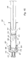
- the applicator device 401 is similar to the applicator device of Figs 10-12 , except that this fifth embodiment includes an air removal system 402, which consists of a separate chamber 403 of the applicator 401 with an air permeable membrane 404, such that the pressure in the chamber 403 is similar to the atmospheric pressure p 2 outside the applicator 401.
- the air removal system 402 communicates with the catheter.
- the blood pressure p 1 in the catheter is higher than the pressure p 2 in the chamber 403. The blood with air bubbles will therefore flow into the chamber 403.
- the plunger 405 When the chamber is filled with blood, the plunger 405 is pressed down, so that the stopper 406 moves downwards and becomes penetrated by the mandrel 407. When the stopper 406 is pressed all the way down, the blood with air is enclosed in the chamber 403. By pressing the plunger 405 further down, the rinsing solution in the forward compartment 409 is pressed into the catheter. With the plunger 405, the seal 410 forms an expulsion arrangement for expelling solution from the applicator 401.
- the back end compartment 411 is filled with a lock solution.
- the valve 410 that separates the tip end compartment 409 with the rinsing solution from the back end compartment 411 is provided with a frangible tip 412.
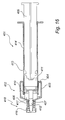
- valve 410 When all rinsing solution has been injected into the catheter, the valve 410 has reached the tip end of the housing, as can be seen in Fig. 16 .
- a valve 410 in the seal is opened and the lock solution of the back end compartment 411 can be injected into the catheter.
- the valve 410 in the seal is constituted by slits in the seal, which are normally closed, but which open when the seal impacts spacers 419 at the tip end of the housing.
- the tip 412 As the plunger 405 is pressed all the way down, the tip 412 is also pressed all the way down and engages the inside of the tip end of the housing and the luer lock in the same way as in the other embodiments described above. Therefore, as the syringe 413 is removed, the tip 412 is left behind, closing the opening of the catheter.
- the tip end of the housing is also broken off and left in the luer lock.
- the two-compartment applicator device 101; 201; 301 may be provided with a small abutment on the plunger 105; 205; 305, so that the nurse or physician is given an indication when the tip end compartment 108; 208; 308 has been emptied.
- the plunger 105; 205; 305 may then be pressed further, past the abutment, for emptying the back end compartment. Otherwise, the injection of the flushing solution and the lock solution may be done in one continuous push.
- the two-compartment applicator device 101; 201; 301 or an applicator with more than two compartments may also be suitable in cases where the components of the lock solution need to be stored separately during sterilization and storage.
- distilled water or a simple buffer solution is contained in one compartment and other components in dry form or in high concentrations are contained in the other compartment(s).
Landscapes
- Health & Medical Sciences (AREA)
- Life Sciences & Earth Sciences (AREA)
- Hematology (AREA)
- Animal Behavior & Ethology (AREA)
- Engineering & Computer Science (AREA)
- Anesthesiology (AREA)
- Biomedical Technology (AREA)
- Heart & Thoracic Surgery (AREA)
- Biophysics (AREA)
- Pulmonology (AREA)
- General Health & Medical Sciences (AREA)
- Public Health (AREA)
- Veterinary Medicine (AREA)
- Infusion, Injection, And Reservoir Apparatuses (AREA)
- Media Introduction/Drainage Providing Device (AREA)
- Materials For Medical Uses (AREA)
Claims (20)
- Eine Vorrichtung zum Einbringen einer Verschlusslösung in einen Katheter oder in ein Zugangssystem, wobei die Einbringungsvorrichtung eine Spritze (2; 102; 202; 302; 413) mit einer Ausstoßanordnung (5; 105, 110; 205, 210; 305, 311, 405, 410) umfasst zum Ausstoßen der Verriegelungslösung aus der Vorrichtung, wobei die Ausstoßanordnung einen Kolben (5; 105; 205; 305; 405) einschließt, der in einem Gehäuse (4; 104; 204; 304; 414) angeordnet ist, wobei die Vorrichtung weiterhin umfasst: einen sterilen Verbinder (3; 6; 103; 203; 303; 416) zum Verbinden der Spritze mit dem Katheter, wobei der Verbinder zum festen Eingriff mit einer Spitze (7; 107; 207; 307; 412) der Ausstoßanordnung angeordnet ist, wenn die Spitze der Ausstoßanordnung der Spritze in den Verbinder eingefügt ist, wobei der Verbinder angeordnet ist, um die Spitze der Ausstoßanordnung am Eintreten in den Katheter zu hindern, wobei die Spitze zerbrechlich ist.
- Eine Vorrichtung nach Anspruch 1, wobei der Verbinder ein Luer-Lock (3; 103; 203; 303; 416) ist.
- Eine Vorrichtung nach Anspruch 1, wobei die zerbrechliche Spitze (7; 107; 207; 307; 412) der Ausstoßanordnung (5; 105, 110; 205, 210; 305, 311; 405, 410) mit einer Umfangsreihe von Einkerbungen (14; 114; 214; 314; 417) versehen ist.
- Eine Vorrichtung nach irgendeinem der Ansprüche 1 bis 3, wobei die zerbrechliche Spitze (7; 107; 207; 307; 412) der Ausstoßanordnung (5; 105, 110; 205, 210; 305, 311; 405, 410) mit einem im wesentlichen radialen Vorsprung versehen ist und eine Innenseite des Verbinders (3; 103; 203; 303; 416) mit einer Aussparung versehen ist, wobei der Vorsprung angeordnet ist, um in die Aussparung einzugreifen.
- Eine Vorrichtung nach irgendeinem der Ansprüche 1 bis 3, wobei die zerbrechliche Spitze (7; 107; 207; 307; 412) der Ausstoßanordnung (5; 105, 110; 205, 210; 305, 311; 405, 410) eine konische Form aufweist, welche fest in eine innere konische Form des Verbinders (3; 103; 203; 303; 416) passt.
- Eine Vorrichtung nach irgendeinem der vorigen Ansprüche, wobei das Gehäuse (104; 204; 304; 414) in ein erstes und ein zweites Teilstück (108, 109; 208, 209; 308, 309; 409, 411) geteilt ist.
- Eine Vorrichtung nach Anspruch 6, wobei das erste Teilstück (108; 208; 308; 409) in einem Spitzenende des Gehäuses (104; 204; 304; 414) mit einer Spüllösung gefüllt ist, und das zweite Teilstück (109; 209; 309; 411) in einem hinteren Ende des Gehäuses (104; 204; 304; 414) mit einer Verschlusslösung gefüllt ist.
- Vorrichtung nach Anspruch 6 oder 7, wobei die Ausstoßanordnung weiterhin einen Teiler (110; 210; 311; 410) umfasst, der das erste und das zweite Teilstück (108, 109; 208, 209; 308, 309; 409, 411) voneinander trennt.
- Eine Vorrichtung nach Anspruch 8, wobei der Teiler eine zerbrechliche Membran (110; 410) ist, und wobei ein Dorn (112, 407) an dem Spitzenende des Gehäuses (104; 414) angeordnet ist, um die Membran (110; 410) zu zerreißen.
- Eine Vorrichtung nach irgendeinem der vorigen Ansprüche, wobei die zerbrechliche Spitze (7; 107) auf dem Kolben (5; 105) angeordnet ist.
- Eine Vorrichtung nach Anspruch 8, wobei die zerbrechliche Spitze (207; 307; 412) auf dem Teiler (210; 311; 410) angeordnet ist.
- Eine Vorrichtung nach Anspruch 11, weiterhin einen Bypass (212) umfassend, der zum Verschieben der Verschlusslösung hinter den Teiler (210) angeordnet ist.
- Eine Vorrichtung nach Anspruch 8, wobei der Teiler eine Dichtung (311; 410) ist, die ein Ventil einschließt, welches durch Herunterdrücken des Kolbens (305; 405) geöffnet werden kann.
- Eine Vorrichtung nach irgendeinem der Ansprüche 6 bis 13, wobei der Kolben (105; 205; 305) mit einem Angrenzmittel versehen ist, um anzuzeigen, wenn das erste Teilstück (108; 208; 308) geleert wurde.
- Eine Vorrichtung nach irgendeinem der Ansprüche 6 bis 14, weiterhin ein Luftentfernungssystem (402) umfassend.
- Eine Vorrichtung nach Anspruch 15, wobei das Luftentfernungssystem (402) eine Kammer (403) umfasst, die von der Atmosphäre durch eine luftdurchlässige Membran (404) abgetrennt ist und welche zur Kommunikation mit dem Katheter oder dem Zugangssystem angeordnet ist, wenn die Spritze (413) mit dem Katheter oder mit dem Zugangssystem verbunden ist.
- Verfahren zum Einbringen einer Verschlusslösung in einen Katheter oder in ein Zugangssystem, umfassend die folgenden Schritte:Verbinden eines sterilen Verbinders, der an einem Spitzenende (6; 106; 206; 306; 418) einer Spritze (2; 102; 202; 302; 413) befestigt ist, mit dem Katheter oder mit einem anderen Zugangssystem,Einspritzen der Verschlusslösung in den Katheter durch Pressen der Ausstoßanordnung der Spritze, einschließlich eines Kolbens (5; 105; 205; 305; 405), wobei dabei eine zerbrechliche Spitze (7; 107; 207; 307; 412) der Ausstoßanordnung (5; 105, 110; 205, 210; 305, 311; 405, 410) in den Verbinder (3; 103; 203; 302; 416) eingreift,Entfernen der Spritze aus dem Verbinder unter Zurücklassung der zerbrechlichen Spitze der Ausstoßanordnung, welche abbricht, wenn die Spritze entfernt wird,Schließen einer Klappe (8; 111; 211; 317) am Verbinder.
- Ein Verfahren nach Anspruch 17, wobei eine Spüllösung zum Spülen des Katheters vor dem Einspritzen der Verschlusslösung injiziert wird.
- Ein Verfahren nach Anspruch 18, wobei die Spüllösung durch ein erstes Drücken auf den Kolben (105; 205; 305; 405) injiziert wird und die Verschlusslösung durch ein zweites Drücken auf den Kolben (105; 205; 305; 405) injiziert wird.
- Ein Verfahren nach Anspruch 18, wobei die Spüllösung und anschließend die Verschlusslösung durch ein kontinuierliches Pressen auf den Kolben (105; 205; 305; 405) injiziert werden.
Applications Claiming Priority (3)
| Application Number | Priority Date | Filing Date | Title |
|---|---|---|---|
| US58048504P | 2004-06-17 | 2004-06-17 | |
| SE0401569A SE0401569D0 (sv) | 2004-06-17 | 2004-06-17 | Applikator |
| PCT/SE2005/000913 WO2005123164A1 (en) | 2004-06-17 | 2005-06-15 | Applicator and method for applying lock solution in a catheter |
Publications (2)
| Publication Number | Publication Date |
|---|---|
| EP1768726A1 EP1768726A1 (de) | 2007-04-04 |
| EP1768726B1 true EP1768726B1 (de) | 2010-12-15 |
Family
ID=32906808
Family Applications (1)
| Application Number | Title | Priority Date | Filing Date |
|---|---|---|---|
| EP05752055A Expired - Lifetime EP1768726B1 (de) | 2004-06-17 | 2005-06-15 | Applikator und Verfahren zum Einbringen einer Verschlusslösung in einem nicht-implantierten Katheter |
Country Status (9)
| Country | Link |
|---|---|
| US (1) | US8454564B2 (de) |
| EP (1) | EP1768726B1 (de) |
| CN (1) | CN100548401C (de) |
| AT (1) | ATE491490T1 (de) |
| AU (1) | AU2005253911B2 (de) |
| CA (1) | CA2549978C (de) |
| DE (1) | DE602005025356D1 (de) |
| SE (1) | SE0401569D0 (de) |
| WO (1) | WO2005123164A1 (de) |
Cited By (1)
| Publication number | Priority date | Publication date | Assignee | Title |
|---|---|---|---|---|
| DE102013015820A1 (de) | 2013-09-24 | 2015-03-26 | G. Pohl-Boskamp Gmbh & Co. Kg | Spritze oder dergleichen mit einer Luer-Lock-Verbindung |
Families Citing this family (9)
| Publication number | Priority date | Publication date | Assignee | Title |
|---|---|---|---|---|
| USD710499S1 (en) * | 2012-12-19 | 2014-08-05 | Daikyo Seiko, Ltd. | Syringe barrel |
| CN103252012A (zh) * | 2013-05-13 | 2013-08-21 | 宁波圣宇瑞医疗器械有限公司 | 医用弯曲导管 |
| CN105792868B (zh) | 2013-12-06 | 2022-05-31 | 豪夫迈·罗氏有限公司 | 用于低体积药物递送的设备和方法 |
| USD785162S1 (en) * | 2015-06-11 | 2017-04-25 | Covidien Lp | Enteral feeding syringe |
| US10130770B2 (en) | 2015-06-11 | 2018-11-20 | Kpr U.S., Llc | Enteral feeding syringe assembly |
| WO2016204858A1 (en) | 2015-06-15 | 2016-12-22 | Hollister Incorporated | Urinary catheters having limited reusability |
| USD858754S1 (en) * | 2017-01-05 | 2019-09-03 | Regeneron Pharmaceuticals, Inc. | Syringe cap |
| WO2020036858A1 (en) | 2018-08-13 | 2020-02-20 | Monumedical, Llc | Syringe with multi-stage filling and dispensing |
| USD969909S1 (en) * | 2020-07-16 | 2022-11-15 | Make Great Sales Limited | Glue device |
Family Cites Families (28)
| Publication number | Priority date | Publication date | Assignee | Title |
|---|---|---|---|---|
| US4027669A (en) * | 1976-04-12 | 1977-06-07 | American Hospital Supply Corporation | Destructible Luer lock syringe and method of destructing same |
| US4353367A (en) * | 1980-11-14 | 1982-10-12 | The Clinipad Corporation | Container for sterilizing a flexible tube |
| ATE56884T1 (de) * | 1985-06-27 | 1990-10-15 | Duphar Int Res | Mehrkammerspritze. |
| US4929230A (en) * | 1988-09-30 | 1990-05-29 | Pfleger Frederick W | Syringe construction |
| DE3930039A1 (de) | 1989-09-06 | 1991-03-07 | Palm Uelo Aarne | Infektvorbeugende katheteranordnung |
| FR2654628B1 (fr) * | 1989-11-23 | 1992-02-28 | Patrice Elfandi | Materiel a injection (seringue et aiguille) inutilisable apres usage. |
| US5338303A (en) * | 1992-09-08 | 1994-08-16 | Design And Engineering Associates | Safety syringes |
| NZ275051A (en) * | 1993-10-28 | 1997-06-24 | Lok Tek Syringe Pty Ltd | Hypodermic syringe has a tapered needle mounting and a retracting device which pulls the needle inside the barrel |
| DE4445969C1 (de) * | 1994-12-22 | 1996-03-14 | Schott Glaswerke | Spritzenzylinder für eine Zweikammer-Fertigspritze, Zweikammer-Fertigspritze und Verfahren zum Herstellen und Füllen derselben |
| DE19602366C1 (de) * | 1996-01-24 | 1997-05-07 | Sievers Hans Hinrich Prof Dr M | Dreiwegehahn |
| US5755696A (en) * | 1997-06-30 | 1998-05-26 | Becton, Dickinson And Company | Syringe filling and delivery device |
| JP2002523150A (ja) * | 1998-08-21 | 2002-07-30 | メドラッド インコーポレーテッド | シリンジ用コネクターとチューブ装置 |
| US6010486A (en) * | 1998-12-18 | 2000-01-04 | Becton Dickinson And Company | Retracting needle syringe |
| US6221052B1 (en) * | 1998-12-18 | 2001-04-24 | Becton, Dickinson And Company | Retracting needle syringe |
| US6368303B1 (en) * | 1999-10-15 | 2002-04-09 | Becton, Dickinson And Company | Retracting needle syringe |
| US6517516B1 (en) * | 1999-10-15 | 2003-02-11 | Becton Dickinson And Company | Method of making a retracting needle syringe |
| US6840291B2 (en) * | 1999-10-15 | 2005-01-11 | Becton Dickinson And Company | Attachment for a medical device |
| JP2001112867A (ja) * | 1999-10-18 | 2001-04-24 | Terumo Corp | 薬剤入りシリンジ |
| US6599269B1 (en) * | 1999-12-03 | 2003-07-29 | Becton Dickinson And Company | Single-use syringe |
| US20010037091A1 (en) * | 1999-12-29 | 2001-11-01 | Wironen John F. | System for reconstituting pastes and methods of using same |
| US7232419B2 (en) * | 2002-02-11 | 2007-06-19 | Baxter International Inc. | Enclosure with cam action snap release |
| US20030153897A1 (en) * | 2002-02-12 | 2003-08-14 | Russo Ronald D. | Closed system drainage and infusion connector valve |
| US20040225258A1 (en) * | 2002-03-30 | 2004-11-11 | Ernest Balestracci | Tamper evident overcap for a container |
| US6911018B2 (en) * | 2002-08-06 | 2005-06-28 | Cosmetic And Medical Inventions, Llc | Safety syringe |
| US6866653B2 (en) * | 2002-10-31 | 2005-03-15 | Kyongtae T. Bae | Method and apparatus for sequential delivery of multiple injectable substances stored in a prefilled syringe |
| ES2530517T3 (es) * | 2003-02-19 | 2015-03-03 | Takeda Pharmaceutical | Jeringa prellenada del tipo de cámara doble |
| US6997910B2 (en) * | 2004-05-03 | 2006-02-14 | Infusive Technologies, Llc | Multi-chamber, sequential dose dispensing syringe |
| US20050251096A1 (en) * | 2004-05-10 | 2005-11-10 | George Armstrong | Syringe assembly with improved cap and luer connector |
-
2004
- 2004-06-17 SE SE0401569A patent/SE0401569D0/xx unknown
-
2005
- 2005-06-15 AU AU2005253911A patent/AU2005253911B2/en not_active Ceased
- 2005-06-15 US US11/629,783 patent/US8454564B2/en not_active Expired - Fee Related
- 2005-06-15 CA CA2549978A patent/CA2549978C/en not_active Expired - Fee Related
- 2005-06-15 CN CNB200580002352XA patent/CN100548401C/zh not_active Expired - Fee Related
- 2005-06-15 AT AT05752055T patent/ATE491490T1/de not_active IP Right Cessation
- 2005-06-15 DE DE602005025356T patent/DE602005025356D1/de not_active Expired - Lifetime
- 2005-06-15 EP EP05752055A patent/EP1768726B1/de not_active Expired - Lifetime
- 2005-06-15 WO PCT/SE2005/000913 patent/WO2005123164A1/en not_active Ceased
Cited By (1)
| Publication number | Priority date | Publication date | Assignee | Title |
|---|---|---|---|---|
| DE102013015820A1 (de) | 2013-09-24 | 2015-03-26 | G. Pohl-Boskamp Gmbh & Co. Kg | Spritze oder dergleichen mit einer Luer-Lock-Verbindung |
Also Published As
| Publication number | Publication date |
|---|---|
| AU2005253911A1 (en) | 2005-12-29 |
| CN100548401C (zh) | 2009-10-14 |
| US8454564B2 (en) | 2013-06-04 |
| ATE491490T1 (de) | 2011-01-15 |
| AU2005253911B2 (en) | 2010-08-26 |
| CA2549978A1 (en) | 2005-12-29 |
| WO2005123164A1 (en) | 2005-12-29 |
| US20110160664A1 (en) | 2011-06-30 |
| SE0401569D0 (sv) | 2004-06-17 |
| CA2549978C (en) | 2013-04-16 |
| CN1909940A (zh) | 2007-02-07 |
| DE602005025356D1 (de) | 2011-01-27 |
| EP1768726A1 (de) | 2007-04-04 |
Similar Documents
| Publication | Publication Date | Title |
|---|---|---|
| EP2094336B1 (de) | Spritze zum sequentiellen ausdrücken unterschiedlicher flüssigkeiten und anwendungsverfahren dafür | |
| KR200396136Y1 (ko) | 타이어 밀봉체를 구비한 의료용 밸브 | |
| US6299609B1 (en) | Methods and apparatus for inhibiting infection of subcutaneously implanted devices | |
| JP2007513690A (ja) | 逆流防止ストッパを有するフラッシュ注射器 | |
| CN101119762A (zh) | 正排量冲洗注射器 | |
| MXPA03010227A (es) | Aguja combinada y dispositivo dilatador para la cateterizacion arterial y de la vena central. | |
| JPH11114064A (ja) | 流体移送装置 | |
| JP3361440B2 (ja) | 採血用器具および採血用器具を用いた血液処理方法 | |
| EP1768726B1 (de) | Applikator und Verfahren zum Einbringen einer Verschlusslösung in einem nicht-implantierten Katheter | |
| US20040171979A1 (en) | Catheter system and method for delivering medication to the bladder | |
| US20040210201A1 (en) | Device for maintaining catheter lumen patency | |
| US20030120201A1 (en) | Methods and devices for sclerotherapy | |
| WO2009031144A1 (en) | Envelope containing sterile needle | |
| US20080294148A1 (en) | System and method for refilling an implanted delivery device | |
| KR101166944B1 (ko) | 카테터에 록 용액을 공급하기 위한 애플리케이터 및 그 방법 | |
| JP7744788B2 (ja) | シリンジシステムおよびプレフィルドシリンジの製造方法 | |
| US20250325750A1 (en) | Multi-Barrel Syringe for Sequential Delivery of Fluids and Methods of Use | |
| US20260069782A1 (en) | Multi-Chamber Syringe With Multiple Plungers for Sequential Delivery of Fluids and Methods of Use | |
| US20200338268A1 (en) | Syringe with dual nested chambers and method of use | |
| ZA200308445B (en) | Combined needle and dilator device for central venous and arterial catheterization. |
Legal Events
| Date | Code | Title | Description |
|---|---|---|---|
| PUAI | Public reference made under article 153(3) epc to a published international application that has entered the european phase |
Free format text: ORIGINAL CODE: 0009012 |
|
| 17P | Request for examination filed |
Effective date: 20070117 |
|
| AK | Designated contracting states |
Kind code of ref document: A1 Designated state(s): AT BE BG CH CY CZ DE DK EE ES FI FR GB GR HU IE IS IT LI LT LU MC NL PL PT RO SE SI SK TR |
|
| RIN1 | Information on inventor provided before grant (corrected) |
Inventor name: DIETRICH, RUTH Inventor name: DEPPISCH, REINHOLD Inventor name: SCHNELL, ANDREA Inventor name: SEIDLER, BJOERN, FREDERIK Inventor name: BECH, WERNER Inventor name: HILDWEIN, CLAUDIA |
|
| RIN1 | Information on inventor provided before grant (corrected) |
Inventor name: BECH, WERNER Inventor name: SCHNELL, ANDREA Inventor name: DEPPISCH, REINHOLD Inventor name: DIETRICH, RUTH Inventor name: SEIDLER, BJOERN, FREDERIK Inventor name: HILDWEIN, CLAUDIA |
|
| DAX | Request for extension of the european patent (deleted) | ||
| 111Z | Information provided on other rights and legal means of execution |
Free format text: AT BE BG CH CY CZ DE DK EE ES FI FR GB GR HU IE IS IT LT LU MC NL PL PT RO SE SI SK TR Effective date: 20081020 |
|
| 17Q | First examination report despatched |
Effective date: 20091221 |
|
| GRAP | Despatch of communication of intention to grant a patent |
Free format text: ORIGINAL CODE: EPIDOSNIGR1 |
|
| RTI1 | Title (correction) |
Free format text: APPLICATOR AND METHOD FOR APPLYING A LOCK-SOLUTION IN A NON-IMPLANTED CATHETER |
|
| GRAS | Grant fee paid |
Free format text: ORIGINAL CODE: EPIDOSNIGR3 |
|
| GRAA | (expected) grant |
Free format text: ORIGINAL CODE: 0009210 |
|
| AK | Designated contracting states |
Kind code of ref document: B1 Designated state(s): AT BE BG CH CY CZ DE DK EE ES FI FR GB GR HU IE IS IT LI LT LU MC NL PL PT RO SE SI SK TR |
|
| REG | Reference to a national code |
Ref country code: GB Ref legal event code: FG4D Ref country code: CH Ref legal event code: EP |
|
| REG | Reference to a national code |
Ref country code: IE Ref legal event code: FG4D |
|
| REF | Corresponds to: |
Ref document number: 602005025356 Country of ref document: DE Date of ref document: 20110127 Kind code of ref document: P |
|
| REG | Reference to a national code |
Ref country code: NL Ref legal event code: VDEP Effective date: 20101215 |
|
| PG25 | Lapsed in a contracting state [announced via postgrant information from national office to epo] |
Ref country code: LT Free format text: LAPSE BECAUSE OF FAILURE TO SUBMIT A TRANSLATION OF THE DESCRIPTION OR TO PAY THE FEE WITHIN THE PRESCRIBED TIME-LIMIT Effective date: 20101215 |
|
| LTIE | Lt: invalidation of european patent or patent extension |
Effective date: 20101215 |
|
| PG25 | Lapsed in a contracting state [announced via postgrant information from national office to epo] |
Ref country code: NL Free format text: LAPSE BECAUSE OF FAILURE TO SUBMIT A TRANSLATION OF THE DESCRIPTION OR TO PAY THE FEE WITHIN THE PRESCRIBED TIME-LIMIT Effective date: 20101215 Ref country code: AT Free format text: LAPSE BECAUSE OF FAILURE TO SUBMIT A TRANSLATION OF THE DESCRIPTION OR TO PAY THE FEE WITHIN THE PRESCRIBED TIME-LIMIT Effective date: 20101215 Ref country code: CY Free format text: LAPSE BECAUSE OF FAILURE TO SUBMIT A TRANSLATION OF THE DESCRIPTION OR TO PAY THE FEE WITHIN THE PRESCRIBED TIME-LIMIT Effective date: 20101215 Ref country code: BG Free format text: LAPSE BECAUSE OF FAILURE TO SUBMIT A TRANSLATION OF THE DESCRIPTION OR TO PAY THE FEE WITHIN THE PRESCRIBED TIME-LIMIT Effective date: 20110315 Ref country code: FI Free format text: LAPSE BECAUSE OF FAILURE TO SUBMIT A TRANSLATION OF THE DESCRIPTION OR TO PAY THE FEE WITHIN THE PRESCRIBED TIME-LIMIT Effective date: 20101215 Ref country code: SI Free format text: LAPSE BECAUSE OF FAILURE TO SUBMIT A TRANSLATION OF THE DESCRIPTION OR TO PAY THE FEE WITHIN THE PRESCRIBED TIME-LIMIT Effective date: 20101215 Ref country code: SE Free format text: LAPSE BECAUSE OF FAILURE TO SUBMIT A TRANSLATION OF THE DESCRIPTION OR TO PAY THE FEE WITHIN THE PRESCRIBED TIME-LIMIT Effective date: 20101215 |
|
| PG25 | Lapsed in a contracting state [announced via postgrant information from national office to epo] |
Ref country code: GR Free format text: LAPSE BECAUSE OF FAILURE TO SUBMIT A TRANSLATION OF THE DESCRIPTION OR TO PAY THE FEE WITHIN THE PRESCRIBED TIME-LIMIT Effective date: 20110316 Ref country code: PT Free format text: LAPSE BECAUSE OF FAILURE TO SUBMIT A TRANSLATION OF THE DESCRIPTION OR TO PAY THE FEE WITHIN THE PRESCRIBED TIME-LIMIT Effective date: 20110415 Ref country code: IS Free format text: LAPSE BECAUSE OF FAILURE TO SUBMIT A TRANSLATION OF THE DESCRIPTION OR TO PAY THE FEE WITHIN THE PRESCRIBED TIME-LIMIT Effective date: 20110415 Ref country code: BE Free format text: LAPSE BECAUSE OF FAILURE TO SUBMIT A TRANSLATION OF THE DESCRIPTION OR TO PAY THE FEE WITHIN THE PRESCRIBED TIME-LIMIT Effective date: 20101215 Ref country code: ES Free format text: LAPSE BECAUSE OF FAILURE TO SUBMIT A TRANSLATION OF THE DESCRIPTION OR TO PAY THE FEE WITHIN THE PRESCRIBED TIME-LIMIT Effective date: 20110326 Ref country code: EE Free format text: LAPSE BECAUSE OF FAILURE TO SUBMIT A TRANSLATION OF THE DESCRIPTION OR TO PAY THE FEE WITHIN THE PRESCRIBED TIME-LIMIT Effective date: 20101215 Ref country code: CZ Free format text: LAPSE BECAUSE OF FAILURE TO SUBMIT A TRANSLATION OF THE DESCRIPTION OR TO PAY THE FEE WITHIN THE PRESCRIBED TIME-LIMIT Effective date: 20101215 |
|
| PG25 | Lapsed in a contracting state [announced via postgrant information from national office to epo] |
Ref country code: RO Free format text: LAPSE BECAUSE OF FAILURE TO SUBMIT A TRANSLATION OF THE DESCRIPTION OR TO PAY THE FEE WITHIN THE PRESCRIBED TIME-LIMIT Effective date: 20101215 Ref country code: PL Free format text: LAPSE BECAUSE OF FAILURE TO SUBMIT A TRANSLATION OF THE DESCRIPTION OR TO PAY THE FEE WITHIN THE PRESCRIBED TIME-LIMIT Effective date: 20101215 Ref country code: SK Free format text: LAPSE BECAUSE OF FAILURE TO SUBMIT A TRANSLATION OF THE DESCRIPTION OR TO PAY THE FEE WITHIN THE PRESCRIBED TIME-LIMIT Effective date: 20101215 |
|
| PLBE | No opposition filed within time limit |
Free format text: ORIGINAL CODE: 0009261 |
|
| STAA | Information on the status of an ep patent application or granted ep patent |
Free format text: STATUS: NO OPPOSITION FILED WITHIN TIME LIMIT |
|
| PG25 | Lapsed in a contracting state [announced via postgrant information from national office to epo] |
Ref country code: DK Free format text: LAPSE BECAUSE OF FAILURE TO SUBMIT A TRANSLATION OF THE DESCRIPTION OR TO PAY THE FEE WITHIN THE PRESCRIBED TIME-LIMIT Effective date: 20101215 |
|
| 26N | No opposition filed |
Effective date: 20110916 |
|
| PG25 | Lapsed in a contracting state [announced via postgrant information from national office to epo] |
Ref country code: IT Free format text: LAPSE BECAUSE OF FAILURE TO SUBMIT A TRANSLATION OF THE DESCRIPTION OR TO PAY THE FEE WITHIN THE PRESCRIBED TIME-LIMIT Effective date: 20101215 |
|
| REG | Reference to a national code |
Ref country code: DE Ref legal event code: R097 Ref document number: 602005025356 Country of ref document: DE Effective date: 20110916 |
|
| REG | Reference to a national code |
Ref country code: CH Ref legal event code: PL |
|
| REG | Reference to a national code |
Ref country code: IE Ref legal event code: MM4A |
|
| PG25 | Lapsed in a contracting state [announced via postgrant information from national office to epo] |
Ref country code: LI Free format text: LAPSE BECAUSE OF NON-PAYMENT OF DUE FEES Effective date: 20110630 Ref country code: IE Free format text: LAPSE BECAUSE OF NON-PAYMENT OF DUE FEES Effective date: 20110615 Ref country code: CH Free format text: LAPSE BECAUSE OF NON-PAYMENT OF DUE FEES Effective date: 20110630 |
|
| PG25 | Lapsed in a contracting state [announced via postgrant information from national office to epo] |
Ref country code: MC Free format text: LAPSE BECAUSE OF NON-PAYMENT OF DUE FEES Effective date: 20110630 |
|
| PG25 | Lapsed in a contracting state [announced via postgrant information from national office to epo] |
Ref country code: LU Free format text: LAPSE BECAUSE OF NON-PAYMENT OF DUE FEES Effective date: 20110615 |
|
| PG25 | Lapsed in a contracting state [announced via postgrant information from national office to epo] |
Ref country code: TR Free format text: LAPSE BECAUSE OF FAILURE TO SUBMIT A TRANSLATION OF THE DESCRIPTION OR TO PAY THE FEE WITHIN THE PRESCRIBED TIME-LIMIT Effective date: 20101215 |
|
| PG25 | Lapsed in a contracting state [announced via postgrant information from national office to epo] |
Ref country code: HU Free format text: LAPSE BECAUSE OF FAILURE TO SUBMIT A TRANSLATION OF THE DESCRIPTION OR TO PAY THE FEE WITHIN THE PRESCRIBED TIME-LIMIT Effective date: 20101215 |
|
| REG | Reference to a national code |
Ref country code: FR Ref legal event code: PLFP Year of fee payment: 12 |
|
| REG | Reference to a national code |
Ref country code: FR Ref legal event code: PLFP Year of fee payment: 13 |
|
| REG | Reference to a national code |
Ref country code: FR Ref legal event code: PLFP Year of fee payment: 14 |
|
| PGFP | Annual fee paid to national office [announced via postgrant information from national office to epo] |
Ref country code: FR Payment date: 20180614 Year of fee payment: 14 |
|
| PG25 | Lapsed in a contracting state [announced via postgrant information from national office to epo] |
Ref country code: FR Free format text: LAPSE BECAUSE OF NON-PAYMENT OF DUE FEES Effective date: 20190630 |
|
| PGFP | Annual fee paid to national office [announced via postgrant information from national office to epo] |
Ref country code: GB Payment date: 20220513 Year of fee payment: 18 |
|
| GBPC | Gb: european patent ceased through non-payment of renewal fee |
Effective date: 20230615 |
|
| PG25 | Lapsed in a contracting state [announced via postgrant information from national office to epo] |
Ref country code: GB Free format text: LAPSE BECAUSE OF NON-PAYMENT OF DUE FEES Effective date: 20230615 |
|
| PGFP | Annual fee paid to national office [announced via postgrant information from national office to epo] |
Ref country code: DE Payment date: 20240521 Year of fee payment: 20 |
|
| REG | Reference to a national code |
Ref country code: DE Ref legal event code: R071 Ref document number: 602005025356 Country of ref document: DE |