EP1768746B1 - Unite d'eclairage destinee a produire une lumiere polarisee lineairement, dirigee sur une surface cible - Google Patents
Unite d'eclairage destinee a produire une lumiere polarisee lineairement, dirigee sur une surface cible Download PDFInfo
- Publication number
- EP1768746B1 EP1768746B1 EP05763137A EP05763137A EP1768746B1 EP 1768746 B1 EP1768746 B1 EP 1768746B1 EP 05763137 A EP05763137 A EP 05763137A EP 05763137 A EP05763137 A EP 05763137A EP 1768746 B1 EP1768746 B1 EP 1768746B1
- Authority
- EP
- European Patent Office
- Prior art keywords
- polarizing
- unit
- lighting unit
- led devices
- light
- Prior art date
- Legal status (The legal status is an assumption and is not a legal conclusion. Google has not performed a legal analysis and makes no representation as to the accuracy of the status listed.)
- Expired - Lifetime
Links
Images

Classifications
-
- A—HUMAN NECESSITIES
- A61—MEDICAL OR VETERINARY SCIENCE; HYGIENE
- A61N—ELECTROTHERAPY; MAGNETOTHERAPY; RADIATION THERAPY; ULTRASOUND THERAPY
- A61N5/00—Radiation therapy
- A61N5/06—Radiation therapy using light
- A61N5/0613—Apparatus adapted for a specific treatment
- A61N5/0616—Skin treatment other than tanning
-
- A—HUMAN NECESSITIES
- A61—MEDICAL OR VETERINARY SCIENCE; HYGIENE
- A61N—ELECTROTHERAPY; MAGNETOTHERAPY; RADIATION THERAPY; ULTRASOUND THERAPY
- A61N5/00—Radiation therapy
- A61N5/06—Radiation therapy using light
- A61N2005/065—Light sources therefor
- A61N2005/0651—Diodes
- A61N2005/0652—Arrays of diodes
-
- A—HUMAN NECESSITIES
- A61—MEDICAL OR VETERINARY SCIENCE; HYGIENE
- A61N—ELECTROTHERAPY; MAGNETOTHERAPY; RADIATION THERAPY; ULTRASOUND THERAPY
- A61N5/00—Radiation therapy
- A61N5/06—Radiation therapy using light
- A61N2005/065—Light sources therefor
- A61N2005/0651—Diodes
- A61N2005/0653—Organic light emitting diodes
-
- A—HUMAN NECESSITIES
- A61—MEDICAL OR VETERINARY SCIENCE; HYGIENE
- A61N—ELECTROTHERAPY; MAGNETOTHERAPY; RADIATION THERAPY; ULTRASOUND THERAPY
- A61N5/00—Radiation therapy
- A61N5/06—Radiation therapy using light
- A61N2005/073—Radiation therapy using light using polarised light
Definitions
- the invention relates to a lighting unit for producing linearly polarized light directed onto a target surface
- the lighting unit comprises at least a source unit producing light at least in the visible spectral range and an optically translucent polarizing front unit providing protection against external effects, the source unit and the polarizing front unit are placed in a housing in which an electric cable passes through.
- polarized, especially linearly polarized light is beneficial to vital functions and is capable for strengthening the organism to combat disorders.
- it can be used for general conditioning.
- animal husbandry it can be used in order to increase yield and to treat certain inflammatory diseases.
- a compact lighting unit which can be installed easily and is able to emit light with required intensity in the proper direction.
- the units are extendable by simple multiplication of them depending on the purpose and the circumstances.
- EP 0,279,002 described an arrangement for producing polarized light where the spectral range of the emitted light is basically found in the UV range. There is no proposal for special use of the polarized light in the visible or a near visible spectral range.
- the document WO 9309847 disclosed a device for photometric stimulation of living cells, where diodes produce light in three separate wavelengths.
- the solution lacks continual emitted light wavelength in the visible or in the near wavelength ranges, therefore no sufficient effects on the living cells were experienced.
- Document DE 203 11 041 U discloses a lighting unit for producing polarized light in the visible and near infrared spectral range, having a panel with a number of LED devices. This document discloses the preamble of claim 1.
- the source unit of the lighting equipment described in the preamble contains at least one panel which has a number of high intensity LED devices arranged in a predetermined pattern on one of its sides.
- the polarizing front unit contains at least one optically transparent rigid carrier, and a polarizing filter foil applied onto the carrier. At least a portion of the housing is made from heat conductive material, and it keeps the polarizing front unit in a fixed position so that they confine a hermetically closed inner space.
- the panel is positioned in a fixed way parallel with the polarizing unit within the inner space so that the high intensity LED devices face towards the polarizing front unit.
- the source unit and the polarizing front unit are curved cylindrically in one dimension, and the direction of polarization of said polarizing filter foil is parallel with the axis of the cylinder.
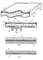
- Figure 1 is a perspective view of a fragment of an exemplary lighting unit, in which a source unit 1 producing light in the visible and optionally in a near infrared spectral range and an optically translucent polarizing front unit 4 providing protection against external effects can be seen.
- Source unit 1 and polarizing unit 4 are placed in a housing 8.
- Source unit 1 contains at least one panel 2 which has a number of high intensity LED devices 3 arranged in a predetermined pattern on one of its sides. In Figure 1 this pattern is a matrix.
- An electric cabel (not shown) passing somewhere through housing 8 supplies energy for LED devices 3.
- the same source unit 1 may contain a number of separate panels 2 or these panels may be attached to each other in a releasable manner.
- the polarizing front unit 4 contains at least one optically transparent rigid carrier 5 and a polarizing filter foil 7 applied onto the carrier 5, which may comprise a Fresnel lens structure.
- housing 8 is made from heat conductive material, for example metal in order to reduce the heat developing during operation.
- heat-insulating paint layer might be proper.
- Polarizing front unit 4 is fixed to housing 8 by means of a frame 9 so that they confine a hermetically closed inner space 11.
- Panel 2 is positioned in a fixed way parallel with the polarizing front unit 4 within inner space 11 so that the high intensity LED devices 3 face towards the polarizing front unit 4.
- cooling flange 16 may also be applied at the bottom part of housing 8 in order to reduce heat developing in the inner space 11.
- LED devices is used for all high-efficiency light emitting semiconductor devices and structures currently manufactured in mass-production and available in trade. These devices and structures are continuously developed in order to reach higher and higher luminous efficiency. Such devices emit light at least within the visible or also in a near infrared spectral range in the form of light emitted in a continuous spectral range, which light may have various colour temperatures.
- LED devices 3 is used in a comprehensive meaning, especially for known high-intensity, high-power LED (Light Emitting Diode) or OLED (Organic Light Emitting Diode) devices. The latter renders possible to use a plane luminous foil which - theoretically - may be cut to an optional size.
- LEP Light Emitting Polymer
- LED devices 3 which are known as SSL (Solid State Lighting) electronic devices in the state of the art. Current possibilities in trade make dominantly the use of discrete LED devices feasible.
- Figure 3 shows the cross-section of a possible structure of the polarizing front unit 4.
- the optically transparent rigid carrier 5 together with a similar carrier 6 form a sandwich structure surrounding the polarizing filter foil 7.
- This polarizing filter foil may be applied onto either carrier 5 or carrier 6. Application may be performed by sticking, heat-treatment, etc. I t is also possible that polarizing filter foil 7 is simply kept in its place by exertion of a mechanical force.
- Polarizing filter foils are known and commercially available.
- the polarizing filter foil 7 is highly transparent, preferably it has a light-transmitting capacity of more than 40%.
- the carriers 5 and 6 are made of plexi-glass, transparent polycarbonate or similar plastic material, however glass or hardened glass may also be appropriate.
- polarizing front unit 4 contains a polarizing filter foil 7 applied onto carrier 5 by using one of the applying methods previously described.
- LED devices 3 are arranged on one of the sides of panel 2 in a predetermined pattern.
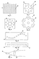
- This pattern may be a matrix containing a number of rows m and columns n as it is shown in Figure 5 or the LED devices 3 may be arranged concentrically as it can be seen in Figure 6 .
- the LED devices 3 may be arranged in an undulating line as it is shown in Figure 9 or they may be distributed along a straight line according to Figure 10 .
- the light source may be different in the same pattern.
- compound LED devices 13 containing several LED components 3' arranged in a starlike pattern as shown in Figure 8 may be used. These LED devices 13 are available in trade.
- the LED devices 3 and compound LED devices 13 may be arranged in like manner as it is shown in Figure 6 .
- LED devices 3 placed in the lighting unit emit warm white light.
- LED devices 3 emitting coloured light are also applied.
- an additional optical element 15 decreasing the light emitting space angle ⁇ of the LED devices 3 may be positioned before the LED devices 3 or at least before some of them. This can be a lens as it is shown in Figure 11 .
- the original space angle ⁇ of the light emitted from LED device 3 is cut down to space angle ⁇ by means of the optical element (lens) 15.
- Space angle ⁇ is smaller than space angle ⁇ . It proves to be good if the resultant space angle ⁇ before the polarizing front unit 4 has an aperture angle of 10-50°.
- the optically transparent rigid carriers 5 or 6 of polarizing front unit 4 may contain a Fresnel lens.
- the lighting unit according to the invention can be used for certain therapeutic purposes - not detailed in the present description - if the intensity of the resultant light measured at a distance of 0.5 m from the polarizing front unit 4 is between 5-60 mW/cm 2 .
- this value is between 30-40 mW/cm 2 .
- a lighting unit according to the invention described with reference to Figure 1 can be seen in Figure 12 .
- Panel 12 of the source unit is bent (curved) so that it has a convex surface with respect to polarizing front unit 14.
- Polarizing front unit 14 is bent (curved) similarly. In this manner the distance between panel 12 and polarizing front unit 14 is constant.
- These bendings (curvings) must be performed in one dimension (in order to guarantee linear polarization) and they result in a cylindrical surface, as it is shown in Figure 12 .
- the direction of polarization of the polarizing filter foil 7 is parallel with the axis of the cylinder.
- the shape of the housing 18 is optional, it may be different from the one shown in the Figure.
- its inner surface is coated with light-reflecting material.
- the filter and the light source are interchanged, and panel 12' containing LED devices 3 is bent so that it has a concave surface with respect to polarizing front unit 14'.
- the shape of the housing 18' is optional, it may be different from the one shown in the Figure.
- the lighting unit in its entirety may be disc-shaped or parallelepiped. Especially the latter has an advantage that the shape of the individual lighting units makes possible to extend it by further units, i.e. several lighting units can be connected (both mechanically and electrically) to each other easily.
- the side of housing 8 is provided with a mechanical connecting element 10 by means of which a plurality of rectangular lighting units 22 can be connected to each other so that their polarizing front units are in the same plane.
- Connecting elements 10 may be provided on all four sides of the housing 8 while counterparts are formed on the opposite sides. In this manner extension according to Figure 15 can be performed easily.
- Connecting element 10 is also shown symbolically in Figure 1 .
- the lighting unit according to the present invention has several advantages, for example in the specific utilization of the enhancement of the productivity of dairy farms. Any other kind of breeding animals can also be a scope of utilisation of the present invention. It can be implemented simply, it is mobile and can be extended easily without the need for changing the already installed units. Further, it does not get overheated in spite of the dust- and vapour- resistant closed housing.
Landscapes
- Health & Medical Sciences (AREA)
- Biomedical Technology (AREA)
- Life Sciences & Earth Sciences (AREA)
- Engineering & Computer Science (AREA)
- Animal Behavior & Ethology (AREA)
- Pathology (AREA)
- Nuclear Medicine, Radiotherapy & Molecular Imaging (AREA)
- Radiology & Medical Imaging (AREA)
- Biophysics (AREA)
- General Health & Medical Sciences (AREA)
- Public Health (AREA)
- Veterinary Medicine (AREA)
- Polarising Elements (AREA)
- Non-Portable Lighting Devices Or Systems Thereof (AREA)
- Arrangement Of Elements, Cooling, Sealing, Or The Like Of Lighting Devices (AREA)
- Planar Illumination Modules (AREA)
Claims (9)
- Unité d'éclairage pour produire une lumière polarisée linéairement dirigée sur une surface cible, ladite unité d'éclairage comprend au moins une unité de source (1) produisant de la lumière au moins dans la plage spectrale visible et facultativement dans la plage spectrale d'infrarouge proche, et une unité avant polarisante optiquement translucide (4) fournissant une protection contre des effets externes, ladite unité de source (1) et ladite unité avant polarisante (4) sont positionnées dans un logement (8) à travers lequel un câble électrique passe, ledit logement maintient ladite unité avant polarisante (4) dans une position fixe pour confiner un espace intérieur fermé (11), ladite unité de source (1) contient au moins un panneau (2) possédant un nombre de dispositifs à LED à haute intensité (3) agencés dans un motif prédéterminé sur un de ses côtés ; ledit panneau (2) est positionné de manière fixe parallèlement à ladite unité polarisante (4) à l'intérieur dudit espace intérieur (11) pour que lesdits dispositifs à LED à haute intensité (3) soient tournés vers ladite unité avant polarisante (4) ; caractérisée en ce que ladite unité avant polarisante (4) contient au moins un support rigide optiquement transparent (5, 6) comprenant au moins une feuille filtrante polarisante (7) appliquée sur ledit support (5,6) ; au moins une partie dudit logement (8) est faite de matériau conducteur de chaleur, ledit espace intérieur étant fermé hermétiquement ; et ladite unité de source (1) et ladite unité avant polarisante (4, 14,14') sont incurvées de façon cylindrique dans une dimension, et la direction de polarisation de ladite feuille filtrante polarisante (7) est parallèle à l'axe du cylindre.
- Unité d'éclairage selon la revendication 1, caractérisée en ce que ladite unité de source (1) contient un nombre de panneaux (2) séparément ou fixés les uns aux autres de manière libérable.
- Unité d'éclairage selon une quelconque des revendications précédentes, caractérisée en ce que ladite feuille filtrante polarisante (7) possède une capacité de transmission de lumière supérieure à 40 %.
- Unité d'éclairage selon une quelconque des revendications précédentes, caractérisée en ce que la majorité desdits dispositifs à LED (3) inclus dans ladite unité d'éclairage émettent une lumière blanche chaude et facultativement une minorité desdits dispositifs à LED positionnés dans ladite unité d'éclairage émettent une lumière colorée.
- Unité d'éclairage selon une quelconque des revendications précédentes, caractérisée en ce qu'un élément optique supplémentaire (15) est positionné au moins avant certains desdits dispositifs à LED (3) afin de réduire l'angle d'espace luminescent (α) desdits dispositifs à LED (3).
- Unité d'éclairage selon une quelconque des revendications précédentes, caractérisée en ce que l'intensité de la lumière résultante mesurée à une distance de 0,5 m à partir de ladite unité avant polarisante (4) est entre 5 et 60 mW/cm2.
- Unité d'éclairage selon une quelconque des revendications précédentes, caractérisée en ce que les courbures ont pour résultat un cylindre complet.
- Unité d'éclairage selon une quelconque des revendications précédentes, caractérisée en ce que le côté dudit logement (8) est pourvu d'un élément de connexion mécanique (10) pour connecter un nombre d'unité d'éclairage (22) les unes aux autres pour que leur unités avant polarisantes (4) soient dans le même plan.
- Unité d'éclairage selon une quelconque des revendications précédentes, caractérisée en ce que la surface intérieure dudit logement (8, 18, 18') est enduite d'un matériau réfléchissant la lumière.
Priority Applications (3)
| Application Number | Priority Date | Filing Date | Title |
|---|---|---|---|
| SI200531489T SI1768746T1 (sl) | 2004-07-08 | 2005-07-08 | Svetlobna enota za proizvajanje linearno polarizirane svetlobe ki je usmerjena na ciljano površino |
| PL05763137T PL1768746T3 (pl) | 2004-07-08 | 2005-07-08 | Moduł oświetleniowy wytwarzający liniowo spolaryzowane światło skierowane na powierzchnię docelową |
| CY20121100242T CY1112636T1 (el) | 2004-07-08 | 2012-03-08 | Φωτιστικη μοναδα για την παραγωγη γραμμικα πολωμενου φωτος, το οποιο κατευθυνεται προς μια επιφανεια στοχου |
Applications Claiming Priority (2)
| Application Number | Priority Date | Filing Date | Title |
|---|---|---|---|
| HU20040400170U HU2874U (en) | 2004-07-08 | 2004-07-08 | Luminaire for producing of linearly polarized light and directing to target area |
| PCT/HU2005/000075 WO2006005976A1 (fr) | 2004-07-08 | 2005-07-08 | Unite d'eclairage destinee a produire une lumiere polarisee lineairement, dirigee sur une surface cible |
Publications (2)
| Publication Number | Publication Date |
|---|---|
| EP1768746A1 EP1768746A1 (fr) | 2007-04-04 |
| EP1768746B1 true EP1768746B1 (fr) | 2012-01-11 |
Family
ID=33017689
Family Applications (1)
| Application Number | Title | Priority Date | Filing Date |
|---|---|---|---|
| EP05763137A Expired - Lifetime EP1768746B1 (fr) | 2004-07-08 | 2005-07-08 | Unite d'eclairage destinee a produire une lumiere polarisee lineairement, dirigee sur une surface cible |
Country Status (12)
| Country | Link |
|---|---|
| US (1) | US7661834B2 (fr) |
| EP (1) | EP1768746B1 (fr) |
| AT (1) | ATE540723T1 (fr) |
| CY (1) | CY1112636T1 (fr) |
| DK (1) | DK1768746T3 (fr) |
| ES (1) | ES2379089T3 (fr) |
| HR (1) | HRP20120151T1 (fr) |
| HU (1) | HU2874U (fr) |
| PL (1) | PL1768746T3 (fr) |
| PT (1) | PT1768746E (fr) |
| SI (1) | SI1768746T1 (fr) |
| WO (1) | WO2006005976A1 (fr) |
Families Citing this family (13)
| Publication number | Priority date | Publication date | Assignee | Title |
|---|---|---|---|---|
| HUP0800340A2 (en) * | 2008-05-28 | 2009-11-30 | Fenyo Marta | Device for skin care with light-therapy |
| KR101359673B1 (ko) * | 2008-06-19 | 2014-02-07 | 삼성전자주식회사 | 면 광원 장치 및 이를 구비하는 백라이트 유닛 |
| KR101359674B1 (ko) * | 2008-08-14 | 2014-02-07 | 삼성전자주식회사 | 면 광원 장치 및 이를 구비하는 백라이트 유닛 |
| USD605334S1 (en) * | 2008-09-10 | 2009-12-01 | Koninklijke Philips Electronics N.V. | Oled luminaire |
| HUP0900580A2 (en) * | 2009-09-16 | 2011-03-28 | Polarium Hangulat Es Koezerzetjavito Kft | Device for light therapy |
| USD620180S1 (en) * | 2010-01-29 | 2010-07-20 | Eglo Leuchten Gmbh | Light fixture |
| USD620630S1 (en) * | 2010-01-29 | 2010-07-27 | Eglo Leuchten Gmbh | Light fixture |
| TWI414860B (zh) * | 2010-03-31 | 2013-11-11 | Young Lighting Technology Corp | 背光模組 |
| TWI435144B (zh) * | 2010-04-12 | 2014-04-21 | Young Lighting Technology Corp | 背光模組 |
| US8292448B2 (en) * | 2010-09-24 | 2012-10-23 | Lg Innotek Co., Ltd. | Flat lighting assembly apparatus including flat lighting module |
| KR102066614B1 (ko) | 2013-02-28 | 2020-01-15 | 엘지이노텍 주식회사 | 조명 장치 |
| AT516127B1 (de) * | 2014-07-28 | 2016-10-15 | Fame Tech Gmbh | Profilelement mit darin aufgenommenen Leuchtmitteln |
| US10484091B2 (en) * | 2017-06-29 | 2019-11-19 | Osram Sylvania Inc. | Light-based fiducial communication |
Citations (4)
| Publication number | Priority date | Publication date | Assignee | Title |
|---|---|---|---|---|
| WO1984003049A1 (fr) * | 1983-02-08 | 1984-08-16 | Ams Automat Mess & Steuertech | Appareil a refroidissement par air pour une irradiation au moyen de lumiere polarisee |
| US4612604A (en) * | 1983-12-23 | 1986-09-16 | Bildsystem Ab | Projector for producing a light spot of polarized light for biostimulation purposes |
| EP0311124A1 (fr) * | 1987-10-07 | 1989-04-12 | "Harrier" Gmbh Gesellschaft Für Den Vertrieb Medizinischer Und Technischer Geräte | Lampe thérapeutique pour biostimulation avec de la lumière polarisée |
| US5176130A (en) * | 1991-10-10 | 1993-01-05 | Interport International, Inc. | Infrared massage device |
Family Cites Families (9)
| Publication number | Priority date | Publication date | Assignee | Title |
|---|---|---|---|---|
| DE2450456A1 (de) * | 1974-10-24 | 1976-05-06 | Bosch Gmbh Robert | Nebelscheinwerfer |
| HU191836B (en) | 1983-05-11 | 1987-04-28 | Mta Koezponti Fiz Kutato Intez | Device for stimulating biological processes |
| EP0279002A1 (fr) | 1987-02-17 | 1988-08-24 | Christoph Dr. Lambertz | Procédé d'irradiation d'êtres vivants, sans détérioration des tissus, avec de la lumière, en particulier de la lumière UV et appareil pour appliquer ce procédé |
| CH685148A5 (de) | 1991-11-20 | 1995-04-13 | Erik Larsen | Vorrichtung zur fotodynamischen Stimulierung von Zellen. |
| DE20018435U1 (de) * | 2000-10-27 | 2001-02-22 | Shining Blick Enterprises Co., Ltd., Taipeh/T'ai-pei | Glühbirne mit darin enthaltenen biegbaren Lampenbirnchen |
| ATE309030T1 (de) * | 2001-01-22 | 2005-11-15 | Eric Larsen | Vorrichtung zur photodynamischen stimulation |
| US7153015B2 (en) | 2001-12-31 | 2006-12-26 | Innovations In Optics, Inc. | Led white light optical system |
| DE10224705A1 (de) * | 2002-06-04 | 2003-12-18 | Uwe Rathsack | Geräte zur positiven Beeinflussung lebender Organismen mittels Licht |
| DE10332771A1 (de) * | 2003-07-17 | 2005-03-03 | Marco Schmidt | Bestrahlungs-Handgerät |
-
2004
- 2004-07-08 HU HU20040400170U patent/HU2874U/hu unknown
-
2005
- 2005-07-08 WO PCT/HU2005/000075 patent/WO2006005976A1/fr not_active Ceased
- 2005-07-08 DK DK05763137.6T patent/DK1768746T3/da active
- 2005-07-08 SI SI200531489T patent/SI1768746T1/sl unknown
- 2005-07-08 PL PL05763137T patent/PL1768746T3/pl unknown
- 2005-07-08 PT PT05763137T patent/PT1768746E/pt unknown
- 2005-07-08 US US11/571,740 patent/US7661834B2/en not_active Expired - Fee Related
- 2005-07-08 AT AT05763137T patent/ATE540723T1/de active
- 2005-07-08 ES ES05763137T patent/ES2379089T3/es not_active Expired - Lifetime
- 2005-07-08 HR HRP20120151TT patent/HRP20120151T1/hr unknown
- 2005-07-08 EP EP05763137A patent/EP1768746B1/fr not_active Expired - Lifetime
-
2012
- 2012-03-08 CY CY20121100242T patent/CY1112636T1/el unknown
Patent Citations (4)
| Publication number | Priority date | Publication date | Assignee | Title |
|---|---|---|---|---|
| WO1984003049A1 (fr) * | 1983-02-08 | 1984-08-16 | Ams Automat Mess & Steuertech | Appareil a refroidissement par air pour une irradiation au moyen de lumiere polarisee |
| US4612604A (en) * | 1983-12-23 | 1986-09-16 | Bildsystem Ab | Projector for producing a light spot of polarized light for biostimulation purposes |
| EP0311124A1 (fr) * | 1987-10-07 | 1989-04-12 | "Harrier" Gmbh Gesellschaft Für Den Vertrieb Medizinischer Und Technischer Geräte | Lampe thérapeutique pour biostimulation avec de la lumière polarisée |
| US5176130A (en) * | 1991-10-10 | 1993-01-05 | Interport International, Inc. | Infrared massage device |
Also Published As
| Publication number | Publication date |
|---|---|
| US20080007948A1 (en) | 2008-01-10 |
| ES2379089T3 (es) | 2012-04-20 |
| PL1768746T3 (pl) | 2012-07-31 |
| EP1768746A1 (fr) | 2007-04-04 |
| PT1768746E (pt) | 2012-03-21 |
| SI1768746T1 (sl) | 2012-07-31 |
| CY1112636T1 (el) | 2016-02-10 |
| HU2874U (en) | 2005-03-29 |
| US7661834B2 (en) | 2010-02-16 |
| HRP20120151T1 (hr) | 2012-05-31 |
| DK1768746T3 (da) | 2012-03-19 |
| WO2006005976A1 (fr) | 2006-01-19 |
| ATE540723T1 (de) | 2012-01-15 |
| HU0400170V0 (en) | 2004-09-28 |
Similar Documents
| Publication | Publication Date | Title |
|---|---|---|
| US7661834B2 (en) | Lighting unit for producing linearly polarized light directed onto a target surface | |
| US8378358B2 (en) | Light emitting device | |
| US8405105B2 (en) | Light emitting device | |
| KR100869573B1 (ko) | 조명용 광학소자의 확산렌즈, 조명용 광학소자 및 그조명장치 | |
| JP2009543348A5 (fr) | ||
| US20240189464A1 (en) | Disinfecting Light Emitting Subcomponent | |
| WO2020010473A1 (fr) | Systèmes d'éclairage à del haute puissance haute performance et procédés associés | |
| WO2018121273A1 (fr) | Lentille, module de source de lumière, et dispositif d'éclairage | |
| EP3166686A1 (fr) | Dispositif d'éclairage pour coupler la lumière provenant d'une source de lumière dans une plaque de guidage de lumière | |
| EP2846086A1 (fr) | Lumière de signalisation pour le transport | |
| WO2018121654A1 (fr) | Lentille, module de source de lumière, et dispositif d'éclairage | |
| US20170184256A1 (en) | Solid-state iilumination system having an array of light shields | |
| US10514150B2 (en) | Solid-state luminaire reflector assembly | |
| CN204534162U (zh) | 照明装置 | |
| US8772802B2 (en) | Light emitting device with transparent plate | |
| KR20100037610A (ko) | 형광등형 led 조명 장치 | |
| TW201032359A (en) | Light emitting device | |
| CN206381501U (zh) | 一种光疗设备 | |
| KR101629933B1 (ko) | 배광과 조도 및 방열 효율이 향상된 cob 조명 장치 | |
| WO2005050588A1 (fr) | Lampe de signalisation | |
| KR20190052915A (ko) | 발광 모듈 | |
| US20190056068A1 (en) | Lamp structure | |
| US11796141B2 (en) | Lighting device comprising an LED strip | |
| JP6137561B2 (ja) | 照明装置 | |
| KR101402356B1 (ko) | 도광판 모듈 |
Legal Events
| Date | Code | Title | Description |
|---|---|---|---|
| PUAI | Public reference made under article 153(3) epc to a published international application that has entered the european phase |
Free format text: ORIGINAL CODE: 0009012 |
|
| 17P | Request for examination filed |
Effective date: 20070116 |
|
| AK | Designated contracting states |
Kind code of ref document: A1 Designated state(s): AT BE BG CH CY CZ DE DK EE ES FI FR GB GR HU IE IS IT LI LT LU LV MC NL PL PT RO SE SI SK TR |
|
| AX | Request for extension of the european patent |
Extension state: AL BA HR MK YU |
|
| 17Q | First examination report despatched |
Effective date: 20101111 |
|
| GRAP | Despatch of communication of intention to grant a patent |
Free format text: ORIGINAL CODE: EPIDOSNIGR1 |
|
| GRAS | Grant fee paid |
Free format text: ORIGINAL CODE: EPIDOSNIGR3 |
|
| GRAA | (expected) grant |
Free format text: ORIGINAL CODE: 0009210 |
|
| AK | Designated contracting states |
Kind code of ref document: B1 Designated state(s): AT BE BG CH CY CZ DE DK EE ES FI FR GB GR HU IE IS IT LI LT LU LV MC NL PL PT RO SE SI SK TR |
|
| AX | Request for extension of the european patent |
Extension state: AL BA HR MK YU |
|
| RAP1 | Party data changed (applicant data changed or rights of an application transferred) |
Owner name: SENSOLITE S.A. |
|
| REG | Reference to a national code |
Ref country code: GB Ref legal event code: FG4D |
|
| REG | Reference to a national code |
Ref country code: CH Ref legal event code: EP |
|
| REG | Reference to a national code |
Ref country code: AT Ref legal event code: REF Ref document number: 540723 Country of ref document: AT Kind code of ref document: T Effective date: 20120115 |
|
| REG | Reference to a national code |
Ref country code: IE Ref legal event code: FG4D |
|
| REG | Reference to a national code |
Ref country code: HR Ref legal event code: TUEP Ref document number: P20120151 Country of ref document: HR |
|
| REG | Reference to a national code |
Ref country code: RO Ref legal event code: EPE |
|
| REG | Reference to a national code |
Ref country code: DE Ref legal event code: R096 Ref document number: 602005032134 Country of ref document: DE Effective date: 20120308 |
|
| REG | Reference to a national code |
Ref country code: DK Ref legal event code: T3 |
|
| REG | Reference to a national code |
Ref country code: NL Ref legal event code: T3 Ref country code: PT Ref legal event code: SC4A Free format text: AVAILABILITY OF NATIONAL TRANSLATION Effective date: 20120308 |
|
| REG | Reference to a national code |
Ref country code: SE Ref legal event code: TRGR |
|
| REG | Reference to a national code |
Ref country code: ES Ref legal event code: FG2A Ref document number: 2379089 Country of ref document: ES Kind code of ref document: T3 Effective date: 20120420 |
|
| REG | Reference to a national code |
Ref country code: HR Ref legal event code: T1PR Ref document number: P20120151 Country of ref document: HR |
|
| REG | Reference to a national code |
Ref country code: SK Ref legal event code: T3 Ref document number: E 11450 Country of ref document: SK |
|
| REG | Reference to a national code |
Ref country code: EE Ref legal event code: FG4A Ref document number: E006464 Country of ref document: EE Effective date: 20120309 |
|
| REG | Reference to a national code |
Ref country code: GR Ref legal event code: EP Ref document number: 20120400765 Country of ref document: GR Effective date: 20120518 |
|
| REG | Reference to a national code |
Ref country code: PL Ref legal event code: T3 |
|
| PLBE | No opposition filed within time limit |
Free format text: ORIGINAL CODE: 0009261 |
|
| STAA | Information on the status of an ep patent application or granted ep patent |
Free format text: STATUS: NO OPPOSITION FILED WITHIN TIME LIMIT |
|
| 26N | No opposition filed |
Effective date: 20121012 |
|
| REG | Reference to a national code |
Ref country code: DE Ref legal event code: R097 Ref document number: 602005032134 Country of ref document: DE Effective date: 20121012 |
|
| REG | Reference to a national code |
Ref country code: HR Ref legal event code: ODRP Ref document number: P20120151 Country of ref document: HR Payment date: 20140702 Year of fee payment: 10 |
|
| PG25 | Lapsed in a contracting state [announced via postgrant information from national office to epo] |
Ref country code: HU Free format text: LAPSE BECAUSE OF FAILURE TO SUBMIT A TRANSLATION OF THE DESCRIPTION OR TO PAY THE FEE WITHIN THE PRESCRIBED TIME-LIMIT Effective date: 20050708 |
|
| PGFP | Annual fee paid to national office [announced via postgrant information from national office to epo] |
Ref country code: LT Payment date: 20140627 Year of fee payment: 10 |
|
| PGFP | Annual fee paid to national office [announced via postgrant information from national office to epo] |
Ref country code: PT Payment date: 20140627 Year of fee payment: 10 Ref country code: IS Payment date: 20140627 Year of fee payment: 10 Ref country code: LU Payment date: 20140724 Year of fee payment: 10 |
|
| PGFP | Annual fee paid to national office [announced via postgrant information from national office to epo] |
Ref country code: RO Payment date: 20140701 Year of fee payment: 10 Ref country code: GR Payment date: 20140730 Year of fee payment: 10 Ref country code: CH Payment date: 20140728 Year of fee payment: 10 Ref country code: BG Payment date: 20140711 Year of fee payment: 10 Ref country code: IE Payment date: 20140725 Year of fee payment: 10 Ref country code: MC Payment date: 20140731 Year of fee payment: 10 Ref country code: NL Payment date: 20140728 Year of fee payment: 10 Ref country code: CZ Payment date: 20140703 Year of fee payment: 10 Ref country code: EE Payment date: 20140701 Year of fee payment: 10 Ref country code: DK Payment date: 20140728 Year of fee payment: 10 Ref country code: FI Payment date: 20140723 Year of fee payment: 10 |
|
| PGFP | Annual fee paid to national office [announced via postgrant information from national office to epo] |
Ref country code: SI Payment date: 20140701 Year of fee payment: 10 Ref country code: SE Payment date: 20140730 Year of fee payment: 10 Ref country code: SK Payment date: 20140704 Year of fee payment: 10 Ref country code: TR Payment date: 20140707 Year of fee payment: 10 Ref country code: GB Payment date: 20140729 Year of fee payment: 10 Ref country code: LV Payment date: 20140702 Year of fee payment: 10 Ref country code: AT Payment date: 20140729 Year of fee payment: 10 |
|
| PGFP | Annual fee paid to national office [announced via postgrant information from national office to epo] |
Ref country code: IT Payment date: 20140729 Year of fee payment: 10 |
|
| PGFP | Annual fee paid to national office [announced via postgrant information from national office to epo] |
Ref country code: BE Payment date: 20140828 Year of fee payment: 10 |
|
| PGFP | Annual fee paid to national office [announced via postgrant information from national office to epo] |
Ref country code: CY Payment date: 20140707 Year of fee payment: 10 |
|
| REG | Reference to a national code |
Ref country code: PT Ref legal event code: MM4A Free format text: LAPSE DUE TO NON-PAYMENT OF FEES Effective date: 20160108 |
|
| REG | Reference to a national code |
Ref country code: FR Ref legal event code: PLFP Year of fee payment: 11 |
|
| REG | Reference to a national code |
Ref country code: HR Ref legal event code: PBON Ref document number: P20120151 Country of ref document: HR Effective date: 20150708 |
|
| REG | Reference to a national code |
Ref country code: LT Ref legal event code: MM4D Effective date: 20150708 |
|
| REG | Reference to a national code |
Ref country code: DK Ref legal event code: EBP Effective date: 20150731 |
|
| PG25 | Lapsed in a contracting state [announced via postgrant information from national office to epo] |
Ref country code: MC Free format text: LAPSE BECAUSE OF NON-PAYMENT OF DUE FEES Effective date: 20150731 |
|
| REG | Reference to a national code |
Ref country code: CH Ref legal event code: PL |
|
| REG | Reference to a national code |
Ref country code: SE Ref legal event code: EUG Ref country code: SK Ref legal event code: MM4A Ref document number: E 11450 Country of ref document: SK Effective date: 20150708 |
|
| REG | Reference to a national code |
Ref country code: AT Ref legal event code: MM01 Ref document number: 540723 Country of ref document: AT Kind code of ref document: T Effective date: 20150708 Ref country code: EE Ref legal event code: MM4A Ref document number: E006464 Country of ref document: EE Effective date: 20150731 |
|
| GBPC | Gb: european patent ceased through non-payment of renewal fee |
Effective date: 20150708 |
|
| PG25 | Lapsed in a contracting state [announced via postgrant information from national office to epo] |
Ref country code: LU Free format text: LAPSE BECAUSE OF NON-PAYMENT OF DUE FEES Effective date: 20150708 |
|
| REG | Reference to a national code |
Ref country code: NL Ref legal event code: MM Effective date: 20150801 |
|
| REG | Reference to a national code |
Ref country code: IE Ref legal event code: MM4A |
|
| PG25 | Lapsed in a contracting state [announced via postgrant information from national office to epo] |
Ref country code: LI Free format text: LAPSE BECAUSE OF NON-PAYMENT OF DUE FEES Effective date: 20150731 Ref country code: IS Free format text: LAPSE BECAUSE OF FAILURE TO SUBMIT A TRANSLATION OF THE DESCRIPTION OR TO PAY THE FEE WITHIN THE PRESCRIBED TIME-LIMIT Effective date: 20160201 Ref country code: GB Free format text: LAPSE BECAUSE OF NON-PAYMENT OF DUE FEES Effective date: 20150708 Ref country code: CY Free format text: LAPSE BECAUSE OF NON-PAYMENT OF DUE FEES Effective date: 20150708 Ref country code: CZ Free format text: LAPSE BECAUSE OF NON-PAYMENT OF DUE FEES Effective date: 20150708 Ref country code: SK Free format text: LAPSE BECAUSE OF NON-PAYMENT OF DUE FEES Effective date: 20150708 Ref country code: IT Free format text: LAPSE BECAUSE OF NON-PAYMENT OF DUE FEES Effective date: 20150708 Ref country code: CH Free format text: LAPSE BECAUSE OF NON-PAYMENT OF DUE FEES Effective date: 20150731 Ref country code: LT Free format text: LAPSE BECAUSE OF NON-PAYMENT OF DUE FEES Effective date: 20150708 Ref country code: BG Free format text: LAPSE BECAUSE OF NON-PAYMENT OF DUE FEES Effective date: 20160331 Ref country code: EE Free format text: LAPSE BECAUSE OF NON-PAYMENT OF DUE FEES Effective date: 20150731 |
|
| PGFP | Annual fee paid to national office [announced via postgrant information from national office to epo] |
Ref country code: DE Payment date: 20160129 Year of fee payment: 11 Ref country code: ES Payment date: 20160129 Year of fee payment: 11 |
|
| REG | Reference to a national code |
Ref country code: SI Ref legal event code: KO00 Effective date: 20160330 |
|
| PG25 | Lapsed in a contracting state [announced via postgrant information from national office to epo] |
Ref country code: RO Free format text: LAPSE BECAUSE OF NON-PAYMENT OF DUE FEES Effective date: 20150708 Ref country code: SI Free format text: LAPSE BECAUSE OF NON-PAYMENT OF DUE FEES Effective date: 20150709 Ref country code: NL Free format text: LAPSE BECAUSE OF NON-PAYMENT OF DUE FEES Effective date: 20150801 Ref country code: LV Free format text: LAPSE BECAUSE OF NON-PAYMENT OF DUE FEES Effective date: 20150708 Ref country code: FI Free format text: LAPSE BECAUSE OF NON-PAYMENT OF DUE FEES Effective date: 20150708 Ref country code: PT Free format text: LAPSE BECAUSE OF NON-PAYMENT OF DUE FEES Effective date: 20160108 Ref country code: SE Free format text: LAPSE BECAUSE OF NON-PAYMENT OF DUE FEES Effective date: 20150709 Ref country code: AT Free format text: LAPSE BECAUSE OF NON-PAYMENT OF DUE FEES Effective date: 20150708 Ref country code: GR Free format text: LAPSE BECAUSE OF NON-PAYMENT OF DUE FEES Effective date: 20160202 |
|
| PGFP | Annual fee paid to national office [announced via postgrant information from national office to epo] |
Ref country code: PL Payment date: 20160108 Year of fee payment: 11 Ref country code: FR Payment date: 20160126 Year of fee payment: 11 |
|
| REG | Reference to a national code |
Ref country code: GR Ref legal event code: ML Ref document number: 20120400765 Country of ref document: GR Effective date: 20160202 |
|
| PG25 | Lapsed in a contracting state [announced via postgrant information from national office to epo] |
Ref country code: IE Free format text: LAPSE BECAUSE OF NON-PAYMENT OF DUE FEES Effective date: 20150708 |
|
| PG25 | Lapsed in a contracting state [announced via postgrant information from national office to epo] |
Ref country code: DK Free format text: LAPSE BECAUSE OF NON-PAYMENT OF DUE FEES Effective date: 20150731 |
|
| REG | Reference to a national code |
Ref country code: DE Ref legal event code: R119 Ref document number: 602005032134 Country of ref document: DE |
|
| PG25 | Lapsed in a contracting state [announced via postgrant information from national office to epo] |
Ref country code: DE Free format text: LAPSE BECAUSE OF NON-PAYMENT OF DUE FEES Effective date: 20170201 Ref country code: FR Free format text: LAPSE BECAUSE OF NON-PAYMENT OF DUE FEES Effective date: 20160801 |
|
| REG | Reference to a national code |
Ref country code: FR Ref legal event code: ST Effective date: 20170331 |
|
| PG25 | Lapsed in a contracting state [announced via postgrant information from national office to epo] |
Ref country code: BE Free format text: LAPSE BECAUSE OF NON-PAYMENT OF DUE FEES Effective date: 20150731 |
|
| PG25 | Lapsed in a contracting state [announced via postgrant information from national office to epo] |
Ref country code: TR Free format text: LAPSE BECAUSE OF NON-PAYMENT OF DUE FEES Effective date: 20150708 |
|
| PG25 | Lapsed in a contracting state [announced via postgrant information from national office to epo] |
Ref country code: PL Free format text: LAPSE BECAUSE OF NON-PAYMENT OF DUE FEES Effective date: 20160708 |
|
| PG25 | Lapsed in a contracting state [announced via postgrant information from national office to epo] |
Ref country code: ES Free format text: LAPSE BECAUSE OF NON-PAYMENT OF DUE FEES Effective date: 20160709 |
|
| REG | Reference to a national code |
Ref country code: ES Ref legal event code: FD2A Effective date: 20181203 |