EP1769209B1 - Wärmetauscher mit flanschen - Google Patents
Wärmetauscher mit flanschen Download PDFInfo
- Publication number
- EP1769209B1 EP1769209B1 EP05790898.0A EP05790898A EP1769209B1 EP 1769209 B1 EP1769209 B1 EP 1769209B1 EP 05790898 A EP05790898 A EP 05790898A EP 1769209 B1 EP1769209 B1 EP 1769209B1
- Authority
- EP
- European Patent Office
- Prior art keywords
- heat exchanger
- exchanger according
- flange
- cheek
- expansion zone
- Prior art date
- Legal status (The legal status is an assumption and is not a legal conclusion. Google has not performed a legal analysis and makes no representation as to the accuracy of the status listed.)
- Expired - Lifetime
Links
Images





Classifications
-
- F—MECHANICAL ENGINEERING; LIGHTING; HEATING; WEAPONS; BLASTING
- F28—HEAT EXCHANGE IN GENERAL
- F28F—DETAILS OF HEAT-EXCHANGE AND HEAT-TRANSFER APPARATUS, OF GENERAL APPLICATION
- F28F9/00—Casings; Header boxes; Auxiliary supports for elements; Auxiliary members within casings
- F28F9/001—Casings in the form of plate-like arrangements; Frames enclosing a heat exchange core
-
- F—MECHANICAL ENGINEERING; LIGHTING; HEATING; WEAPONS; BLASTING
- F28—HEAT EXCHANGE IN GENERAL
- F28F—DETAILS OF HEAT-EXCHANGE AND HEAT-TRANSFER APPARATUS, OF GENERAL APPLICATION
- F28F2265/00—Safety or protection arrangements; Arrangements for preventing malfunction
- F28F2265/26—Safety or protection arrangements; Arrangements for preventing malfunction for allowing differential expansion between elements
Definitions
- the invention relates to a heat exchanger, in particular a heat exchanger for the equipment of a motor vehicle.
- Conventional heat exchangers comprise a bundle of tubes delimited by two end tubes.
- spacers may be provided between the tubes of the bundle to improve the heat exchange.
- An end spacer may be disposed on the outer face of each of the end tubes.
- the exchanger further comprises two collector plates traversed by the ends of the bundle of tubes. Furthermore, a cheek is conventionally arranged directly on the end spacer of one of the end tubes.
- the cheeks of a heat exchanger and form spacer between the collector plates to maintain a constant spacing between them and facilitate the manufacture of the exchanger. Furthermore, they can be used to support and maintain accessory bodies related to the heat exchanger, such as a motor-fan unit.
- each cheek comprises a central core, bordered by two longitudinal wings that extend along the cheek.
- the central core is usually rectangular and flat.
- Each longitudinal wing protrudes from the plane defined by the central core.
- the cheek thus has a substantially U-shaped cross section.
- the longitudinal wings are conventionally designed to stiffen and strengthen the associated cheek.
- the conventional heat exchanger tubes tend to have a relatively small thickness, to limit the manufacturing costs of the exchanger.
- the tubes are less and less resistant to thermal shocks and the risks of rupture mentioned above increase accordingly.
- the patent FR 2 183 375 proposes a transverse fold, in the form of a lyre, on the bracket which connects the cheek to the collector plate or directly on the cheek.
- the patent application EP 1 195 573 proposes an opening on each cheek so that a portion of the edge of the opening is located near an edge of the cheek. Furthermore, a fold is provided which extends transversely from the aforementioned portion of the edge of the opening to the edge of the cheek located in its vicinity.
- the present invention improves the situation.
- the invention proposes a heat exchanger, in particular for a motor vehicle, comprising a bundle of tubes and spacers interposed between the tubes of the bundle to promote the exchange of heat.
- the beam is delimited by two end spacers.
- the exchanger further comprises two collector plates, intended to be traversed by the ends of the beam, and at least one cheek disposed on one of the end spacers.
- the cheek comprises at least one expansion zone to compensate for longitudinal expansions of the cheek, while the cross section of the cheek in the dilation zone is substantially U-shaped.
- the cheek comprises a substantially flat central core, bordered by two longitudinal wings and in that the expansion zone comprises an opening arranged in the central core and two lateral folds directed towards the inside of the cheek, the lateral folds being arranged on either side of the longitudinal axis of the cheek and each lateral fold extending over part of the wings and on the corresponding part of the zone of connection of the wings to the central core.
- the figure 1 shows a heat exchanger 1, including a heat exchanger for a motor vehicle.
- the heat exchanger 1 comprises a tube bundle 2 parallel to each other and arranged between two collector plates 4. Each collector plate 4 is traversed by one end of the bundle. Each collecting plate 4 is covered by a collecting box 3.
- Heat exchangers in the form of corrugated spacers 7 are inserted between the tubes 2.
- the heat exchange may take place between the refrigerant fluid circulating in the tube and the air passing through the spacers 7.
- the spacers 7 maintain a spacing between the tubes, and limit the deformation of the tubes when they are traversed by a refrigerant underpressure.
- the bundle of tubes is delimited by two end tubes 20 and 21 respectively corresponding to the upper end tube and the lower end tube of the bundle.
- the terms "upper tube” and “lower tube” are used with reference to the position of the heat exchanger of the figure 1 .
- the tubes 2, 20 and 21 are substantially horizontal.
- the exchanger may be arranged such that the tubes 2, 20 and 21 are oriented vertically, and in this case, the end tubes are side tubes.
- end tubes 20 and 21 may be designated respectively by “upper tube” and “lower tube”, for clarity.
- an end spacer 70 is disposed on the outer face of the upper tube and an end spacer 71 is disposed on the outer face of the lower tube 21.
- these end spacers 70 and 71 may designated respectively by “upper interlayer” and “lower spacer”.
- the heat exchanger further comprises at least one cheek disposed on one of the end spacers. So, with reference to the figure 1 , the heat exchanger comprises a cheek 50 disposed on the upper spacer 70 and a cheek 51 disposed on the lower spacer 71. The cheeks 50 and 51 are provided to maintain a constant gap between the collector plates and facilitate the manufacture of the exchanger.
- connection between the upper tube 20, the spacer 70, the collector plates 4 and the cheek 50 is generally made by brazing.
- a refrigerant enters through one of the manifolds 3 and flows through the tubes of the bundle.
- the high temperature of the coolant causes heat transfer to the walls of the tube and the spacers.
- the air passing through the spacers makes it possible to cool the refrigerant flowing through the tubes.
- the tubes then tend to expand longitudinally, under the effect of a high temperature of the refrigerant, which causes high stresses at the area of attachment of the tubes to the collector plates.
- each cheek 50 or 51 maintains a spacing between the collector plates, which opposes the longitudinal expansion of the tubes.
- the temperature of each cheek does not rise at the same time as that of the corresponding end tube, insofar as the cheek is not in direct thermal contact with the refrigerant.
- Each cheek 50 or 51 is in fact in contact with the corresponding end spacer 70 or 71, along its length, so that the pressure exerted inside the corresponding end tube 20 or 21 is transmitted. to the cheek by the end spacer.
- the cheeks have a differential expansion which can cause deformation of parts of the exchanger.
- the exchanger 1 comprises on each cheek 50 and 51 expansion zones, hereinafter designated by the respective references 80 and 81. These zones are schematically represented by the hatched areas of the figure 1 .
- the Figure 2A is a diagram showing a top view of a portion of the upper cheek 50, according to a first embodiment of the invention.
- the invention will be described with reference to the upper cheek 50. However, it may be applied in a similar manner to the lower cheek 51.
- the cheek 50 generally has a generally U-shaped cross section.
- it comprises a central core 500, substantially flat, bordered by two longitudinal wings 501 and 502.
- the wings are generally perpendicular to the plane of the central core 500 and are disposed at the edges of the cheek 50.
- each longitudinal wing 501 and 502 makes protruding from the plane defined by the central core 500.
- the longitudinal wings have the role of reinforcing and stiffening the cheek 50.
- the cheek 50 comprises an expansion zone 80, adapted to compensate for a thermal expansion that would occur longitudinally on the cheek, and the cheek also has a U-shaped cross section in this expansion zone.
- the zone of expansion is represented by the rectangular zone 80 in broken lines.
- the expansion zone 80 is shaped so as to reduce the tensile stiffness of the cheek and thus compensate for longitudinal thermal expansion. It is further shaped so that the bending stiffness of the cheek is sufficient to ensure acceptable vibration resistance.
- the expansion zone 80 has an opening 800 arranged in the central core and two lateral folds 871 and 872.
- Each side fold 871 or 872 is directed towards the inside of the cheek.
- the lateral folds 871 or 872 are in particular directed toward each other.
- the lateral folds may be symmetrical with each other with respect to the longitudinal axis ⁇ of the cheek.
- the opening 800 facilitates the production of lateral folds, and the lateral folds make it possible to compensate for the expansion of the cheek.
- Each lateral fold 871 or 872 extends over that part of the wing 501 or 502 located in the expansion zone, as well as over the corresponding part of the zone of connection of the wing 501 to the central core 500.
- the wings 501, 502 are connected to the central core 500 in the expansion zone 80.
- the connection zone may, for example, have substantially a dihedral shape.
- Each lateral fold 871 or 872 may furthermore extend over a corresponding portion of the central core 500.
- the tip of each lateral fold 871 or 87 is disposed substantially in the middle of the expansion zone 80 along the longitudinal axis ⁇ of the cheek.
- the lateral folds 871 and 872 can be obtained by deformations of the cheek, towards the inside of the cheek, according to lines of vertical folds passing through the middle of the dilation zone.
- vertical designates the direction perpendicular to the plane of the central core 500. This term is used here with reference to the position of the exchanger of the figure 1 , to clarify more.
- the deformations 871 and 872 are such that in the expansion zone, the U-shape of the cross-section of the cheek is retained.
- the dimensions of the U-shaped section of the cheek gradually decrease towards the middle of the expansion zone, along the longitudinal axis ⁇ . This U-shape promotes the rigidity of the cheek and therefore the resistance to vibrations.
- the length of the opening 800 and the length of the side folds 871 and 872 may be substantially equal to the length of the expansion zone L1.
- the ratio between the length L1 of the expansion zone 80 and the width Lj of the cheek may be substantially between 0.5 and 1.5.
- the ratio between the depth L5 of each of the side folds 871 and 872 and the width Lj of the cheek is preferably substantially between 0.05 and 0.3.
- the opening 800 makes it possible to weaken the cheek along the longitudinal axis ⁇ of the cheek.
- the cheek is adapted to break under the effect of a relatively low stress, resulting from longitudinal expansion.
- the lateral folds 871 and 872 of the wings and the zone of connection of the wings to the central core, in the zone of expansion 80, further contribute to weaken the cheek longitudinally. Moreover, they make it possible to maintain a rigidity in bending of the satisfactory cheek, in the plane perpendicular to the plane of the central core 500. Such rigidity is necessary for keeping the cheek vibrating.
- the exchanger according to the invention makes it possible to keep the U-section of the cheek along its entire length, and consequently to obtain a satisfactory flexural rigidity in the zone. of dilation 80.
- the opening 800 according to the first embodiment of the invention may have a substantially rectangular shape whose width may be substantially equal to the width Lj of the cheek 50.
- the longitudinal edges of the opening 800 may be slightly curved inwards, under the effect of the deformations used to form the side folds 871 and 872.
- the plate 50 may comprise a single expansion zone 80.
- the distance between the center of the expansion area 80, passing through the axis ⁇ M, and one of the collector plates 4 is substantially between 75 mm and 300 mm.
- the cheek 50 may comprise two expansion zones 80.
- each expansion zone 80 is located near one of the collector plates.
- the opening 800 may have a general shape of M, whose legs 808 and 809 are generally oriented along the longitudinal axis ⁇ of the cheek.
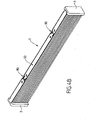
- FIGS. 4A and 4B show perspective views of a heat exchanger according to the second embodiment of the invention.
- the upper cheek 50 of the heat exchanger comprises two expansion zones 80.
- the legs of the M of each expansion zone may be oriented toward the nearby collector plate, as shown in FIG. Figure 4A .
- the legs of the M of each of the expansion zones 80 may be oriented towards the center of the cheek, as shown in FIG. Figure 4B .
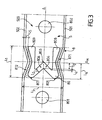
- the figure 3 is a diagram showing a top view of a portion of the cheek 50 showing an expansion zone 80 according to the second embodiment of the invention.
- the M-shaped opening 800 has a central tip 803 and two lateral tips 805 and 807.
- the legs 808 and 809 are connected by two branches 804 and 806. These connecting branches further delimit the central tip 803 of the "M". According to one aspect of the invention, the ratio between the width L2 of each connection branch 804 and 806 and the width Lj of the cheek is substantially between 0.05 and 0.25.
- the distance L4 between the upper edge of the central tip 803 and the lower edge of each lateral tip 805 and 807 is substantially between -5mm and + 5mm.
- the distance L6 between the lower edge of the central tip 803 and the upper edge of each lateral tip 805 and 807 is substantially greater than or equal to the width L2 of the branches of the central tip 803, and is substantially less than or equal to the length L1 of the expansion zone 80.
- Such dimensions allow to adapt the shape of the opening 800 to the width of the cheek and to maintain the folds of tabs pressed against the tube during brazing.
- positioning holes 801 and 802 can be provided on either side of each of the expansion zones 80. These positioning holes make it possible to hold the cheek in the tool, and thus to avoid a variation in length. of the cheek during the realization of the opening 800.
- the width of the M-shaped opening 800 is preferably substantially less than the width L 1 of the cheek.
- a band of peripheral material is delimited between each edge of the cheek and the corresponding longitudinal edge of the M, in the portion of the core 500 of the expansion zone 80.
- the strips of material are indicated by hatching on the figure 3 . These peripheral material strips make it possible to adapt the rigidity in flexion of the cheek 50, for example to the width of the cheek.
- These strips of material are preferably between about 0 mm and 3 mm.
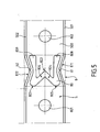
- the figure 5 is a diagram showing a top view of a portion of the cheek, according to a variant of the second embodiment of the cheek.
- a slot 61 or 62 may be provided on the inner wall of each lateral fold 871 and 872, at the tip of the lateral fold. More specifically, each slot extends along the fold line of the corresponding lateral fold, on the inner wall thereof.
- Each slot 61 and 62 preferably has a V-shaped cross section, the tip of the V being oriented towards the outside of the cheek.
- the slots 61 and 62 facilitate the folding of the wings 501 and 502, in case of longitudinal expansion.
- the opening 800 and the lateral folds 871 and 872 of the expansion zone 80 weaken the central core 500 to compensate for longitudinal expansion of the cheek, while promoting flexural stiffness, in the plane perpendicular to the plane of the cheek. blade.
- the lateral folds 871 and 872 of the expansion zone can make it possible to hold the upper interlayer pressed against the upper tube during brazing.
- the lateral tips 805 and 807 of the M-shaped opening also contribute to holding the upper spacer 70 pressed against the upper tube during brazing.
- FIG 6 is a partial view of the cheek 50 assembled to the spacer 70.
- Providing a free interleaf pleat increases the suppleness of the cheek, while maintaining an alternating pressure resistance of the satisfactory tube.
- the heated end tubes can expand under the effect of heating.
- the cheeks can then undergo differential expansion relative to the end tubes.
- this differential expansion is compensated by the expansion zone 80, according to the invention, which is deformed so as not to postpone the stresses on the ends of the exchanger.
- the cheek according to the invention can be made by profiling. Alternatively, it can be obtained by stamping.
- the opening 800 can be obtained by cutting the cheek in the dilation zone.
- the lateral folds 871 and 872 can be made by a deformation of the wings and the zone of connection of the wings to the soul, towards the inside of the cheek.
- the bundle of tubes is first assembled, with spacers 7 inserted between the tubes 2 and tabs 70 and 71 disposed on the end tubes 20 and 21 respectively.
- the tubes of the bundle are then engaged in the collector plates 4, then the flanges 50 and 51 are fixed to the collector plates.
- the assembled exchanger is then brazed.
- the manifolds 3 can be mounted after soldering the exchanger. Alternatively, they can be brazed with the bundle of tubes.
- the side tips 805 and 807 of the aperture 800 "M" make it possible to hold the upper spacer 70 pressed against the tube, during brazing.
- the present invention is not limited to the embodiments described above. It encompasses all the embodiments that may be envisaged by those skilled in the art.
- the invention is not limited to an opening 800 in the general shape of a rectangle or an opening in the general shape of "M”. Other forms can be envisaged.
- an 800 opening general form of "X”, as represented on the figure 7 could be used to implement the invention.
Landscapes
- Engineering & Computer Science (AREA)
- Physics & Mathematics (AREA)
- Thermal Sciences (AREA)
- Mechanical Engineering (AREA)
- General Engineering & Computer Science (AREA)
- Heat-Exchange Devices With Radiators And Conduit Assemblies (AREA)
- Details Of Heat-Exchange And Heat-Transfer (AREA)
Claims (18)
- Wärmetauscher, insbesondere für ein Kraftfahrzeug, der ein Rohrbündel (2) und Einlagen trägt, die zwischen die Rohre des Bündels eingefügt sind, um den Wärmeaustausch zu begünstigen, wobei das Bündel von zwei Endeinlagen (70, 71) abgegrenzt ist, wobei der Austauscher ferner zwei Sammelplatten aufweist, die dazu bestimmt sind, von den Enden des Bündels durchquert zu werden, und mindestens eine Backe (50, 51), die auf einer der Endeinlagen angeordnet ist, wobei die Backe oder die Backen eine zentrale Seele (500), die im Wesentlichen eben ist, aufweisen, die von zwei Längsrippen (501, 502) umrandet ist, und mindestens einen Dehnungsbereich (80), um die Längsdehnungen der Backe zu kompensieren, der eine Öffnung (800), die in der zentralen Seele (500) eingerichtet ist, aufweist, und zwei seitliche Falten (871, 872), die zum Inneren der Backe gerichtet sind, wobei die seitlichen Falten zu beiden Seiten der Längsachse der Backe (Δ) angeordnet sind,
dadurch gekennzeichnet, dass die Rippen (501, 502) an die zentrale Seele (500) in dem Dehnungsbereich (80) angeschlossen sind, wobei sich jede seitliche Falte auf einem Teil der Rippen und auf dem entsprechenden Teil des Anschlussbereichs der Rippen an die zentrale Seele erstreckt, was dem Querschnitt der Backe in dem Dehnungsbereich eine U-Form verleiht. - Wärmetauscher nach Anspruch 1, dadurch gekennzeichnet, dass die seitlichen Falten im Wesentlichen in Bezug zu der Längsachse der Backe (Δ) untereinander symmetrisch sind.
- Wärmetauscher nach einem der Ansprüche 1 oder 2, dadurch gekennzeichnet, dass die Öffnung (800) des Dehnungsbereichs (80) eine Länge im Wesentlichen gleich der Länge der seitlichen Falten (871, 872) hat.
- Wärmetauscher nach einem der Ansprüche 2 und 3, dadurch gekennzeichnet, dass die Spitze jeder seitlichen Falte im Wesentlichen in der Mitte des Dehnungsbereichs entlang der Längsachse der Backe (Δ) liegt.
- Wärmetauscher nach einem der vorhergehenden Ansprüche, dadurch gekennzeichnet, dass die Backe einen einzigen Dehnungsbereich (80) aufweist und dass die Entfernung zwischen der Mitte des Dehnungsbereichs und einer der Sammelplatten im Wesentlichen zwischen 75 mm und 300 mm liegt.
- Wärmetauscher nach einem der vorhergehenden Ansprüche, dadurch gekennzeichnet, dass die Backe zwei Dehnungsbereiche aufweist, wobei sich jeder Dehnungsbereich in der Nähe einer Sammelplatte befindet.
- Wärmetauscher nach einem der vorhergehenden Ansprüche, dadurch gekennzeichnet, dass die Öffnung (800) des Dehnungsbereichs eine allgemein rechteckige Form hat.
- Wärmetauscher nach einem der Ansprüche 1 bis 6, dadurch gekennzeichnet, dass die Öffnung (800) des Dehnungsbereichs eine allgemeine "X"-Form hat.
- Wärmetauscher nach einem der Ansprüche 1 bis 6, dadurch gekennzeichnet, dass die Öffnung eine allgemeine "M"-Form hat, wobei die Schenkel des "M" (808, 809) entlang der Längsachse der Backe (Δ) ausgerichtet sind.
- Wärmetauscher nach Anspruch 9, kombiniert mit Anspruch 6, dadurch gekennzeichnet, dass die Schenkel des "M" zu der Mitte der Backe gerichtet sind.
- Wärmetauscher nach Anspruch 9, kombiniert mit Anspruch 6, dadurch gekennzeichnet, dass die Schenkel des "M" zu der benachbarten Sammelplatte gerichtet sind.
- Wärmetauscher nach einem der Ansprüche 9 bis 11, dadurch gekennzeichnet, dass das Verhältnis zwischen der Breite (L2) der Anschlusszweige (804, 806) der Schenkel des "M" und der Länge (L1) der Backe im Wesentlichen zwischen 0,05 und 0,25 liegt.
- Wärmetauscher nach einem der Ansprüche 9 bis 12, dadurch gekennzeichnet, dass die Entfernung (L4) zwischen dem oberen Rand der zentralen Spitze (830) des M und dem unteren Rand jeder seitlichen Spitze des M (805, 807) im Wesentlichen zwischen -5 mm und +5 mm liegt.
- Wärmetauscher nach einem der Ansprüche 9 bis 13, dadurch gekennzeichnet, dass die Entfernung (L6) zwischen dem unteren Rand der zentralen Spitze (803) und dem oberen Rand jeder seitlichen Spitze (805, 807) im Wesentlichen größer oder gleich der Breite (L2) der Anschlusszweige (804, 806) der Schenkel des "M" und im Wesentlichen kleiner oder gleich der Länge (L1) des Dehnungsbereichs (80) ist.
- Wärmetauscher nach einem der vorhergehenden Ansprüche, dadurch gekennzeichnet, dass jede seitliche Falte (871, 872) auf ihrer Innenwand einen Schlitz (61, 62) mit einer Richtung im Wesentlichen senkrecht zu der Ebene der zentralen Seele auf dem Niveau der Spitze der seitlichen Falte aufweist.
- Wärmetauscher nach Anspruch 15, dadurch gekennzeichnet, dass jeder Schlitz (61, 62) einen Querschnitt in allgemeiner V-Form hat, wobei die Spitze des V zur Außenseite der Backe ausgerichtet ist.
- Wärmetauscher nach einem der vorhergehenden Ansprüche, dadurch gekennzeichnet, dass das Verhältnis zwischen der Länge (L1) des Dehnungsbereichs und der Breite der Backe (Lj) im Wesentlichen zwischen 0,5 und 1,5 liegt.
- Wärmetauscher nach einem der vorhergehenden Ansprüche, dadurch gekennzeichnet, dass das Verhältnis zwischen der Tiefe (L5) jeder seitlichen Falte und der Breite (Lj) der Backe im Wesentlichen zwischen 0,05 und 0,3 liegt.
Priority Applications (2)
| Application Number | Priority Date | Filing Date | Title |
|---|---|---|---|
| PL05790898T PL1769209T3 (pl) | 2004-07-20 | 2005-07-19 | Wymiennik ciepła wyposażony w płyty boczne |
| EP10182795.4A EP2282155A3 (de) | 2004-07-20 | 2005-07-19 | Seitenteil und Wärmetauscher mit Seitenteilen |
Applications Claiming Priority (2)
| Application Number | Priority Date | Filing Date | Title |
|---|---|---|---|
| FR0408018A FR2873434B1 (fr) | 2004-07-20 | 2004-07-20 | Echangeur de chaleur muni de joues |
| PCT/FR2005/001841 WO2006018498A1 (fr) | 2004-07-20 | 2005-07-19 | Echangeur de chaleur muni de joues |
Related Child Applications (1)
| Application Number | Title | Priority Date | Filing Date |
|---|---|---|---|
| EP10182795.4 Division-Into | 2010-09-29 |
Publications (2)
| Publication Number | Publication Date |
|---|---|
| EP1769209A1 EP1769209A1 (de) | 2007-04-04 |
| EP1769209B1 true EP1769209B1 (de) | 2013-05-22 |
Family
ID=34949812
Family Applications (2)
| Application Number | Title | Priority Date | Filing Date |
|---|---|---|---|
| EP05790898.0A Expired - Lifetime EP1769209B1 (de) | 2004-07-20 | 2005-07-19 | Wärmetauscher mit flanschen |
| EP10182795.4A Withdrawn EP2282155A3 (de) | 2004-07-20 | 2005-07-19 | Seitenteil und Wärmetauscher mit Seitenteilen |
Family Applications After (1)
| Application Number | Title | Priority Date | Filing Date |
|---|---|---|---|
| EP10182795.4A Withdrawn EP2282155A3 (de) | 2004-07-20 | 2005-07-19 | Seitenteil und Wärmetauscher mit Seitenteilen |
Country Status (7)
| Country | Link |
|---|---|
| US (1) | US8136579B2 (de) |
| EP (2) | EP1769209B1 (de) |
| JP (1) | JP4966852B2 (de) |
| CN (1) | CN100513979C (de) |
| FR (1) | FR2873434B1 (de) |
| PL (1) | PL1769209T3 (de) |
| WO (1) | WO2006018498A1 (de) |
Families Citing this family (19)
| Publication number | Priority date | Publication date | Assignee | Title |
|---|---|---|---|---|
| WO2006105925A1 (de) * | 2005-04-05 | 2006-10-12 | Behr Gmbh & Co. Kg | Wärmeübertrager, insbesondere für ein kraftfahrzeug |
| DE102006017610B4 (de) | 2006-04-12 | 2020-08-06 | Mahle International Gmbh | Wärmetauscher zur Ladeluftkühlung für Kraftfahrzeuge, System |
| PL1921412T3 (pl) * | 2006-11-09 | 2018-08-31 | Valeo Autosystemy Sp. Z O.O. | Wymiennik ciepła zawierający ulepszone płyty boczne |
| FR2916836B1 (fr) * | 2007-05-30 | 2015-06-26 | Valeo Systemes Thermiques | Echangeur de chaleur muni de joues perforees |
| US8844610B2 (en) * | 2008-09-18 | 2014-09-30 | Multistack, LLC | Double inlet heat exchanger |
| US20110024081A1 (en) * | 2009-07-29 | 2011-02-03 | Christian Riondet | End plate with area of weakness for a heat exchanger |
| CN102261864A (zh) * | 2010-05-28 | 2011-11-30 | 扬州英谛车材实业有限公司 | 一种新型散热器芯子支撑板 |
| JP5009413B2 (ja) * | 2010-12-22 | 2012-08-22 | シャープ株式会社 | 熱交換器及びそれを搭載した空気調和機 |
| DE102011082797A1 (de) * | 2011-09-15 | 2013-03-21 | Behr Gmbh & Co. Kg | Wärmeübertrager zum Kühlen von Ladeluft |
| CN103344134B (zh) * | 2013-07-04 | 2015-08-12 | 江苏扬工动力机械有限公司 | 散热器 |
| ES2759920T3 (es) | 2013-10-23 | 2020-05-12 | Modine Mfg Co | Intercambiador de calor y placa lateral |
| CN105571374B (zh) * | 2016-01-12 | 2018-03-27 | 宁波市哈雷换热设备有限公司 | 一种换热器翅片及具有该换热器翅片的换热器 |
| US10429133B2 (en) * | 2016-08-04 | 2019-10-01 | Hanon Systems | Heat exchanger element with thermal expansion feature |
| FR3055697B1 (fr) | 2016-09-02 | 2019-05-03 | Valeo Systemes Thermiques | Support de brasage pour echangeur de chaleur, echangeur de chaleur associe. |
| DE102017206113A1 (de) * | 2017-04-10 | 2018-10-11 | Mahle International Gmbh | Wärmeübertrager für ein Kraftfahrzeug |
| KR102182776B1 (ko) * | 2019-03-15 | 2020-11-25 | 에스트라오토모티브시스템 주식회사 | 차량용 열교환기 |
| US20210333055A1 (en) * | 2020-04-28 | 2021-10-28 | Hamilton Sundstrand Corporation | Stress relieving additively manufactured heat exchanger fin design |
| US20210381778A1 (en) * | 2020-06-04 | 2021-12-09 | Denso International America, Inc. | Heat exchanger with thermal stress-relief areas |
| DE102023200937A1 (de) * | 2023-02-06 | 2024-08-08 | Mahle International Gmbh | Thermomanagementmodul |
Family Cites Families (16)
| Publication number | Priority date | Publication date | Assignee | Title |
|---|---|---|---|---|
| FR2183375A5 (de) | 1972-05-04 | 1973-12-14 | Chausson Usines Sa | |
| US4719967A (en) * | 1987-06-22 | 1988-01-19 | General Motors Corporation | Heat exchanger core with shearable reinforcements |
| JPH0630123Y2 (ja) * | 1989-07-25 | 1994-08-17 | 象印マホービン株式会社 | 調理器用ランプヒータの制御装置 |
| JPH0359971U (de) * | 1989-10-16 | 1991-06-12 | ||
| US5404940A (en) * | 1993-07-23 | 1995-04-11 | Modine Manufacturing Co. | Tie bar clip construction for heat exchangers |
| GB2303437A (en) * | 1995-06-12 | 1997-02-19 | Ford Motor Co | Stress relief in heat exchangers |
| DE19753408B4 (de) * | 1997-12-02 | 2005-08-18 | Behr Gmbh & Co. Kg | Wärmeübertrager für ein Kraftfahrzeug |
| US6129142A (en) * | 1997-12-18 | 2000-10-10 | Alliedsignal Inc. | Radiator thermal expansion joint and method for making the same |
| US6328098B1 (en) * | 1998-11-10 | 2001-12-11 | Valeo Inc. | Side member for heat exchanger and heat exchanger incorporating side plate |
| US6269868B1 (en) * | 1999-07-02 | 2001-08-07 | Visteon Global Technologies, Inc. | Heat exchanger with variable compression side support |
| JP2002147973A (ja) * | 2000-08-30 | 2002-05-22 | Denso Corp | 複式熱交換器 |
| US6412547B1 (en) * | 2000-10-04 | 2002-07-02 | Modine Manufacturing Company | Heat exchanger and method of making the same |
| JP2003202198A (ja) * | 2002-01-08 | 2003-07-18 | Denso Corp | 熱交換器 |
| BR0304406A (pt) * | 2002-04-09 | 2004-07-27 | Behr Gmbh & Co | Unidade transmissora de calor, especialmente para um veìculo automóvel |
| US7143512B2 (en) * | 2003-11-19 | 2006-12-05 | Delphi Technologies, Inc. | Method of making a brazed metal heat exchanger core with self-shearing reinforcement |
| BRPI0507276A (pt) | 2004-02-02 | 2007-06-26 | Behr Gmbh & Co Kg | chapa lateral para radiador |
-
2004
- 2004-07-20 FR FR0408018A patent/FR2873434B1/fr not_active Expired - Lifetime
-
2005
- 2005-07-19 JP JP2007521982A patent/JP4966852B2/ja not_active Expired - Lifetime
- 2005-07-19 WO PCT/FR2005/001841 patent/WO2006018498A1/fr not_active Ceased
- 2005-07-19 EP EP05790898.0A patent/EP1769209B1/de not_active Expired - Lifetime
- 2005-07-19 EP EP10182795.4A patent/EP2282155A3/de not_active Withdrawn
- 2005-07-19 US US11/632,792 patent/US8136579B2/en active Active
- 2005-07-19 PL PL05790898T patent/PL1769209T3/pl unknown
- 2005-07-19 CN CNB2005800301794A patent/CN100513979C/zh not_active Expired - Lifetime
Also Published As
| Publication number | Publication date |
|---|---|
| EP2282155A2 (de) | 2011-02-09 |
| US8136579B2 (en) | 2012-03-20 |
| CN101014822A (zh) | 2007-08-08 |
| EP2282155A3 (de) | 2013-05-22 |
| EP1769209A1 (de) | 2007-04-04 |
| FR2873434A1 (fr) | 2006-01-27 |
| JP4966852B2 (ja) | 2012-07-04 |
| JP2008506924A (ja) | 2008-03-06 |
| WO2006018498A1 (fr) | 2006-02-23 |
| FR2873434B1 (fr) | 2017-12-29 |
| CN100513979C (zh) | 2009-07-15 |
| PL1769209T3 (pl) | 2013-11-29 |
| US20080169090A1 (en) | 2008-07-17 |
Similar Documents
| Publication | Publication Date | Title |
|---|---|---|
| EP2282155A2 (de) | Seitenteil und Wärmetauscher mit Seitenteilen | |
| EP0811820B1 (de) | Flachrohr mit einem in der Mitte befindlichen Distanzhalter für Wärmetauscher | |
| EP1192402B1 (de) | Wärmetauscher mit mehrkanalrohren | |
| EP2553375B1 (de) | Wärmetauscher und platten für den wärmetauscher | |
| EP0767354A1 (de) | Wärmetauscher, insbesondere Ladeluftkühler für Kraftfahrzeug | |
| FR3056734B1 (fr) | Echangeur thermique, notamment pour vehicule automobile | |
| WO2008148605A1 (fr) | Echangeur de chaleur muni de joues perforees | |
| EP2113447B1 (de) | Kraftfahrzeugstruktur, ihr Herstellungsverfahren und Fahrzeug, das eine solche Struktur umfasst | |
| EP1579162B1 (de) | Wärmetauschermodul und verfahren zur herstellung | |
| EP1978325B1 (de) | Seitenteil mit Abschwächungszone für Wärmetauscher | |
| EP0284463A1 (de) | Wärmeaustauscher mit systematischen Durchlaufen mit an mindestens einer Endplatte durch elastische Buchsen verbundenen Rohren | |
| FR2892804A1 (fr) | Boite collectrice pour echangeur de chaleur, notamment pour evaporateur de climatisation, echangeur comportant une telle boite et procede pour sa fabrication | |
| EP1150087B1 (de) | Wärmetauscher mit raumsparendem Sammelkasten, insbesondere für Kraftfahrzeuge | |
| EP3001133B1 (de) | Wärmetauscher für kraftfahrzeug | |
| WO2005100901A1 (fr) | Tubes d'echangeur de chaleur favorisant le drainage des condensats | |
| WO2006010856A1 (fr) | Echangeur de chaleur muni de joues laterales | |
| FR3059403B1 (fr) | Joue pour echangeur thermique de vehicule automobile | |
| EP1957927A1 (de) | Verstärkter sammler für den sammelbehälter eines wärmetauschers und einen solchen sammler umfassender sammelbehälter | |
| FR2725644A1 (fr) | Tube, notamment pour radiateur de vehicule automobile | |
| FR2858385A1 (fr) | Embout de tube pour element de circuit hydraulique, en particulier pour echangeur de chaleur | |
| FR2817334A1 (fr) | Echangeur de chaleur brase, notamment pour vehicule automobile, et son procede de fabrication | |
| WO2017134359A1 (fr) | Échangeur de chaleur a tubes améliorés | |
| FR2858399A1 (fr) | Embout de tube pour element de circuit hydraulique, en particulier pour echangeur de chaleur | |
| FR2884308A1 (fr) | Plaque laterale a utiliser avec un echangeur de chaleur et procede de realisation de cet echangeur | |
| FR2902506A1 (fr) | Echangeur de chaleur ayant au moins une traverse d'extremite et son procede d'assemblage |
Legal Events
| Date | Code | Title | Description |
|---|---|---|---|
| PUAI | Public reference made under article 153(3) epc to a published international application that has entered the european phase |
Free format text: ORIGINAL CODE: 0009012 |
|
| 17P | Request for examination filed |
Effective date: 20070115 |
|
| AK | Designated contracting states |
Kind code of ref document: A1 Designated state(s): AT BE BG CH CY CZ DE DK EE ES FI FR GB GR HU IE IS IT LI LT LU LV MC NL PL PT RO SE SI SK TR |
|
| DAX | Request for extension of the european patent (deleted) | ||
| 17Q | First examination report despatched |
Effective date: 20081202 |
|
| GRAP | Despatch of communication of intention to grant a patent |
Free format text: ORIGINAL CODE: EPIDOSNIGR1 |
|
| GRAS | Grant fee paid |
Free format text: ORIGINAL CODE: EPIDOSNIGR3 |
|
| GRAA | (expected) grant |
Free format text: ORIGINAL CODE: 0009210 |
|
| AK | Designated contracting states |
Kind code of ref document: B1 Designated state(s): AT BE BG CH CY CZ DE DK EE ES FI FR GB GR HU IE IS IT LI LT LU LV MC NL PL PT RO SE SI SK TR |
|
| REG | Reference to a national code |
Ref country code: GB Ref legal event code: FG4D Free format text: NOT ENGLISH |
|
| REG | Reference to a national code |
Ref country code: CH Ref legal event code: EP |
|
| REG | Reference to a national code |
Ref country code: AT Ref legal event code: REF Ref document number: 613439 Country of ref document: AT Kind code of ref document: T Effective date: 20130615 |
|
| REG | Reference to a national code |
Ref country code: IE Ref legal event code: FG4D Free format text: LANGUAGE OF EP DOCUMENT: FRENCH |
|
| REG | Reference to a national code |
Ref country code: DE Ref legal event code: R096 Ref document number: 602005039722 Country of ref document: DE Effective date: 20130718 |
|
| REG | Reference to a national code |
Ref country code: AT Ref legal event code: MK05 Ref document number: 613439 Country of ref document: AT Kind code of ref document: T Effective date: 20130522 |
|
| REG | Reference to a national code |
Ref country code: LT Ref legal event code: MG4D |
|
| PG25 | Lapsed in a contracting state [announced via postgrant information from national office to epo] |
Ref country code: LT Free format text: LAPSE BECAUSE OF FAILURE TO SUBMIT A TRANSLATION OF THE DESCRIPTION OR TO PAY THE FEE WITHIN THE PRESCRIBED TIME-LIMIT Effective date: 20130522 Ref country code: ES Free format text: LAPSE BECAUSE OF FAILURE TO SUBMIT A TRANSLATION OF THE DESCRIPTION OR TO PAY THE FEE WITHIN THE PRESCRIBED TIME-LIMIT Effective date: 20130902 Ref country code: FI Free format text: LAPSE BECAUSE OF FAILURE TO SUBMIT A TRANSLATION OF THE DESCRIPTION OR TO PAY THE FEE WITHIN THE PRESCRIBED TIME-LIMIT Effective date: 20130522 Ref country code: PT Free format text: LAPSE BECAUSE OF FAILURE TO SUBMIT A TRANSLATION OF THE DESCRIPTION OR TO PAY THE FEE WITHIN THE PRESCRIBED TIME-LIMIT Effective date: 20130923 Ref country code: SI Free format text: LAPSE BECAUSE OF FAILURE TO SUBMIT A TRANSLATION OF THE DESCRIPTION OR TO PAY THE FEE WITHIN THE PRESCRIBED TIME-LIMIT Effective date: 20130522 Ref country code: IS Free format text: LAPSE BECAUSE OF FAILURE TO SUBMIT A TRANSLATION OF THE DESCRIPTION OR TO PAY THE FEE WITHIN THE PRESCRIBED TIME-LIMIT Effective date: 20130922 Ref country code: SE Free format text: LAPSE BECAUSE OF FAILURE TO SUBMIT A TRANSLATION OF THE DESCRIPTION OR TO PAY THE FEE WITHIN THE PRESCRIBED TIME-LIMIT Effective date: 20130522 Ref country code: GR Free format text: LAPSE BECAUSE OF FAILURE TO SUBMIT A TRANSLATION OF THE DESCRIPTION OR TO PAY THE FEE WITHIN THE PRESCRIBED TIME-LIMIT Effective date: 20130823 Ref country code: AT Free format text: LAPSE BECAUSE OF FAILURE TO SUBMIT A TRANSLATION OF THE DESCRIPTION OR TO PAY THE FEE WITHIN THE PRESCRIBED TIME-LIMIT Effective date: 20130522 |
|
| REG | Reference to a national code |
Ref country code: NL Ref legal event code: VDEP Effective date: 20130522 |
|
| PG25 | Lapsed in a contracting state [announced via postgrant information from national office to epo] |
Ref country code: BG Free format text: LAPSE BECAUSE OF FAILURE TO SUBMIT A TRANSLATION OF THE DESCRIPTION OR TO PAY THE FEE WITHIN THE PRESCRIBED TIME-LIMIT Effective date: 20130822 |
|
| REG | Reference to a national code |
Ref country code: PL Ref legal event code: T3 |
|
| PG25 | Lapsed in a contracting state [announced via postgrant information from national office to epo] |
Ref country code: LV Free format text: LAPSE BECAUSE OF FAILURE TO SUBMIT A TRANSLATION OF THE DESCRIPTION OR TO PAY THE FEE WITHIN THE PRESCRIBED TIME-LIMIT Effective date: 20130522 |
|
| BERE | Be: lapsed |
Owner name: VALEO SYSTEMES THERMIQUES Effective date: 20130731 |
|
| PG25 | Lapsed in a contracting state [announced via postgrant information from national office to epo] |
Ref country code: SK Free format text: LAPSE BECAUSE OF FAILURE TO SUBMIT A TRANSLATION OF THE DESCRIPTION OR TO PAY THE FEE WITHIN THE PRESCRIBED TIME-LIMIT Effective date: 20130522 Ref country code: DK Free format text: LAPSE BECAUSE OF FAILURE TO SUBMIT A TRANSLATION OF THE DESCRIPTION OR TO PAY THE FEE WITHIN THE PRESCRIBED TIME-LIMIT Effective date: 20130522 Ref country code: EE Free format text: LAPSE BECAUSE OF FAILURE TO SUBMIT A TRANSLATION OF THE DESCRIPTION OR TO PAY THE FEE WITHIN THE PRESCRIBED TIME-LIMIT Effective date: 20130522 |
|
| PG25 | Lapsed in a contracting state [announced via postgrant information from national office to epo] |
Ref country code: RO Free format text: LAPSE BECAUSE OF FAILURE TO SUBMIT A TRANSLATION OF THE DESCRIPTION OR TO PAY THE FEE WITHIN THE PRESCRIBED TIME-LIMIT Effective date: 20130522 Ref country code: NL Free format text: LAPSE BECAUSE OF FAILURE TO SUBMIT A TRANSLATION OF THE DESCRIPTION OR TO PAY THE FEE WITHIN THE PRESCRIBED TIME-LIMIT Effective date: 20130522 Ref country code: IT Free format text: LAPSE BECAUSE OF FAILURE TO SUBMIT A TRANSLATION OF THE DESCRIPTION OR TO PAY THE FEE WITHIN THE PRESCRIBED TIME-LIMIT Effective date: 20130522 Ref country code: MC Free format text: LAPSE BECAUSE OF FAILURE TO SUBMIT A TRANSLATION OF THE DESCRIPTION OR TO PAY THE FEE WITHIN THE PRESCRIBED TIME-LIMIT Effective date: 20130522 |
|
| REG | Reference to a national code |
Ref country code: CH Ref legal event code: PL |
|
| PLBI | Opposition filed |
Free format text: ORIGINAL CODE: 0009260 |
|
| PLAX | Notice of opposition and request to file observation + time limit sent |
Free format text: ORIGINAL CODE: EPIDOSNOBS2 |
|
| 26 | Opposition filed |
Opponent name: MAHLE INTERNATIONAL GMBH Effective date: 20140220 |
|
| GBPC | Gb: european patent ceased through non-payment of renewal fee |
Effective date: 20130822 |
|
| REG | Reference to a national code |
Ref country code: IE Ref legal event code: MM4A |
|
| PG25 | Lapsed in a contracting state [announced via postgrant information from national office to epo] |
Ref country code: CH Free format text: LAPSE BECAUSE OF NON-PAYMENT OF DUE FEES Effective date: 20130731 Ref country code: LI Free format text: LAPSE BECAUSE OF NON-PAYMENT OF DUE FEES Effective date: 20130731 Ref country code: BE Free format text: LAPSE BECAUSE OF NON-PAYMENT OF DUE FEES Effective date: 20130731 |
|
| REG | Reference to a national code |
Ref country code: DE Ref legal event code: R026 Ref document number: 602005039722 Country of ref document: DE Effective date: 20140220 |
|
| PG25 | Lapsed in a contracting state [announced via postgrant information from national office to epo] |
Ref country code: GB Free format text: LAPSE BECAUSE OF NON-PAYMENT OF DUE FEES Effective date: 20130822 Ref country code: IE Free format text: LAPSE BECAUSE OF NON-PAYMENT OF DUE FEES Effective date: 20130719 |
|
| PLBB | Reply of patent proprietor to notice(s) of opposition received |
Free format text: ORIGINAL CODE: EPIDOSNOBS3 |
|
| PG25 | Lapsed in a contracting state [announced via postgrant information from national office to epo] |
Ref country code: CY Free format text: LAPSE BECAUSE OF FAILURE TO SUBMIT A TRANSLATION OF THE DESCRIPTION OR TO PAY THE FEE WITHIN THE PRESCRIBED TIME-LIMIT Effective date: 20130522 Ref country code: TR Free format text: LAPSE BECAUSE OF FAILURE TO SUBMIT A TRANSLATION OF THE DESCRIPTION OR TO PAY THE FEE WITHIN THE PRESCRIBED TIME-LIMIT Effective date: 20130522 |
|
| PG25 | Lapsed in a contracting state [announced via postgrant information from national office to epo] |
Ref country code: LU Free format text: LAPSE BECAUSE OF NON-PAYMENT OF DUE FEES Effective date: 20130719 Ref country code: HU Free format text: LAPSE BECAUSE OF FAILURE TO SUBMIT A TRANSLATION OF THE DESCRIPTION OR TO PAY THE FEE WITHIN THE PRESCRIBED TIME-LIMIT; INVALID AB INITIO Effective date: 20050719 |
|
| REG | Reference to a national code |
Ref country code: FR Ref legal event code: PLFP Year of fee payment: 11 |
|
| PLCK | Communication despatched that opposition was rejected |
Free format text: ORIGINAL CODE: EPIDOSNREJ1 |
|
| APBM | Appeal reference recorded |
Free format text: ORIGINAL CODE: EPIDOSNREFNO |
|
| APBP | Date of receipt of notice of appeal recorded |
Free format text: ORIGINAL CODE: EPIDOSNNOA2O |
|
| APAH | Appeal reference modified |
Free format text: ORIGINAL CODE: EPIDOSCREFNO |
|
| REG | Reference to a national code |
Ref country code: DE Ref legal event code: R100 Ref document number: 602005039722 Country of ref document: DE |
|
| APBU | Appeal procedure closed |
Free format text: ORIGINAL CODE: EPIDOSNNOA9O |
|
| PLBN | Opposition rejected |
Free format text: ORIGINAL CODE: 0009273 |
|
| STAA | Information on the status of an ep patent application or granted ep patent |
Free format text: STATUS: OPPOSITION REJECTED |
|
| 27O | Opposition rejected |
Effective date: 20160225 |
|
| REG | Reference to a national code |
Ref country code: FR Ref legal event code: PLFP Year of fee payment: 12 |
|
| REG | Reference to a national code |
Ref country code: FR Ref legal event code: PLFP Year of fee payment: 13 |
|
| REG | Reference to a national code |
Ref country code: FR Ref legal event code: PLFP Year of fee payment: 14 |
|
| P01 | Opt-out of the competence of the unified patent court (upc) registered |
Effective date: 20230528 |
|
| PGFP | Annual fee paid to national office [announced via postgrant information from national office to epo] |
Ref country code: PL Payment date: 20240625 Year of fee payment: 20 |
|
| PGFP | Annual fee paid to national office [announced via postgrant information from national office to epo] |
Ref country code: DE Payment date: 20240712 Year of fee payment: 20 |
|
| PGFP | Annual fee paid to national office [announced via postgrant information from national office to epo] |
Ref country code: FR Payment date: 20240725 Year of fee payment: 20 |
|
| PGFP | Annual fee paid to national office [announced via postgrant information from national office to epo] |
Ref country code: CZ Payment date: 20240717 Year of fee payment: 20 |
|
| REG | Reference to a national code |
Ref country code: DE Ref legal event code: R071 Ref document number: 602005039722 Country of ref document: DE |
|
| PG25 | Lapsed in a contracting state [announced via postgrant information from national office to epo] |
Ref country code: CZ Free format text: LAPSE BECAUSE OF EXPIRATION OF PROTECTION Effective date: 20250719 |