EP1769883A1 - Dispositif pour nettoyage de la tige et de la surface de contact d'une machine outil - Google Patents
Dispositif pour nettoyage de la tige et de la surface de contact d'une machine outil Download PDFInfo
- Publication number
- EP1769883A1 EP1769883A1 EP05021119A EP05021119A EP1769883A1 EP 1769883 A1 EP1769883 A1 EP 1769883A1 EP 05021119 A EP05021119 A EP 05021119A EP 05021119 A EP05021119 A EP 05021119A EP 1769883 A1 EP1769883 A1 EP 1769883A1
- Authority
- EP
- European Patent Office
- Prior art keywords
- stripping
- contact surface
- shaft
- tool
- cleaning
- Prior art date
- Legal status (The legal status is an assumption and is not a legal conclusion. Google has not performed a legal analysis and makes no representation as to the accuracy of the status listed.)
- Granted
Links
Images


Classifications
-
- B—PERFORMING OPERATIONS; TRANSPORTING
- B23—MACHINE TOOLS; METAL-WORKING NOT OTHERWISE PROVIDED FOR
- B23Q—DETAILS, COMPONENTS, OR ACCESSORIES FOR MACHINE TOOLS, e.g. ARRANGEMENTS FOR COPYING OR CONTROLLING; MACHINE TOOLS IN GENERAL CHARACTERISED BY THE CONSTRUCTION OF PARTICULAR DETAILS OR COMPONENTS; COMBINATIONS OR ASSOCIATIONS OF METAL-WORKING MACHINES, NOT DIRECTED TO A PARTICULAR RESULT
- B23Q11/00—Accessories fitted to machine tools for keeping tools or parts of the machine in good working condition or for cooling work; Safety devices specially combined with or arranged in, or specially adapted for use in connection with, machine tools
- B23Q11/0042—Devices for removing chips
- B23Q11/005—Devices for removing chips by blowing
-
- B—PERFORMING OPERATIONS; TRANSPORTING
- B08—CLEANING
- B08B—CLEANING IN GENERAL; PREVENTION OF FOULING IN GENERAL
- B08B1/00—Cleaning by methods involving the use of tools
- B08B1/30—Cleaning by methods involving the use of tools by movement of cleaning members over a surface
- B08B1/32—Cleaning by methods involving the use of tools by movement of cleaning members over a surface using rotary cleaning members
- B08B1/34—Cleaning by methods involving the use of tools by movement of cleaning members over a surface using rotary cleaning members rotating about an axis parallel to the surface
Definitions
- the invention relates to a device according to the preamble of claim 1.
- Such devices are widely used in practice and for example from the EP 1 179 388 B1 known.
- the cleaning elements of these devices consist of brushes, by means of which, in the case of a corresponding rotary drive of the brushes, the shaft or the contact surface are cleaned.
- This embodiment has the disadvantage that the brush wear on the one hand and on the other hand pollute itself. After a certain period of operation, they therefore no longer clean reliably.
- the invention is therefore the object of developing a device of the generic type so that a perfect cleaning of shaft and contact surface of a machine tool is permanently guaranteed.
- the device shown in the drawing for cleaning the shaft and the contact surface of a machine tool has a housing 1, which may be attached to a machine tool or a transport device for transporting tools from a magazine to a tool spindle of a machine tool, as for example in US Pat of the EP 1 179 388 B1 is shown and described.
- a tool clamping device 2 is arranged, which has a tension rod 3.
- This clamping rod 3 has on her one - in Fig. 1 lower end - not shown jaws, which engage in a cavity of a HSK shaft 4 of a tool 5, wherein "HSK" has the meaning of "hollow shaft cone".
- the tension rod 3 is loaded with a biased against the housing 1 biased screw-pressure spring 6, the displacements of the tension rod 3 by this spring 6, So away from the tool 5, which spreads in the cavity of the shaft 4 located clamping jaws and thus the tool 5 pulls into the housing 1 and holds.
- the shaft 4 is radially fixed by the clamping device 2.
- the clamping rod 3 is loosened in the opposite direction by means of a piston 7 attached to the end of the clamping rod 3 opposite the tool 5, which can be acted upon by a pressure medium connection 8 with pressure medium, as a rule with pressure fluid, so that a release the tension rod 3 is against the force of the spring 6.
- Such tool clamping devices 2 are common in tool spindles and are also used in devices for cleaning tool shanks, as shown in EP 1 179 388 B1 evident.
- a scraper sleeve 9 is rotatably mounted, which is rotatably driven by means of a mounted on the housing 1 gear motor 10.
- the drive transmission takes place by means of a toothed pinion 11 attached to the motor 10, which engages in a toothed ring 12 mounted on the stripper sleeve 9.
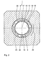
- stripping sleeve 9 On the stripping sleeve 9 are distributed over the inner circumference distributed a plurality of shank stripping plates 13 for stripping the surface of the HSK shaft 4. Furthermore, a plurality of contact surface stripping plates 14 are attached to the stripping sleeve 9, which serve for stripping, that is, cleaning the contact surface 14 of the tool 5.
- This contact surface 15 extends radially to the central longitudinal axis 16 of the tool 5 and serves to rest against a corresponding alignment counter-surface on the tool clamping device of the tool spindle of a machine tool.
- the HSK shaft 4 is received in a corresponding cone of the tool clamping device of the tool spindle.
- the shank stripping plates 13, 14 are made of spring steel.
- the shank stripping plates 13 are fastened by means of screws 17 to the inner wall 18 of the stripping sleeve 9. They extend in the direction of the axis 16 over the area which is to be cleaned on the shaft 4. They have at their two in the direction of the axis 16 extending, in the circumferential direction of the inner wall 18 of the sleeve 9 spaced edges stripping edges 19, 20 which rest elastically resiliently against the cone-shaped shaft 4, so when turning the stripping sleeve. 9 by means of the motor 10 about the axis 16, both the leading and the trailing scraper edge 19 and 20 chips, dirt and the like from the shaft 4 strip.
- the contact surface stripping plates 14 are fastened by means of screws 22. They have an elastically resilient abutting on the contact surface 15 stripping edge 23, the cleaning effect is naturally best when it - relative to the direction of rotation 24 of the stripping sleeve 9 - is arranged leading.
- Both the wiper edges 19, 20, and the wiper edge 23 extend obliquely from the shaft stripping plate 13 or from the contact surface stripping plate 14 away from the shaft 4 and the contact surface 15, so that their cleaning or stripping effect always best, if they - are arranged leading in relation to the direction of rotation 24.
- the shaft 4 is secured against twisting during cleaning by the fact that projections 25 formed on the tensioning rod 3 engage in corresponding recesses 26 on the shaft 4.
- a flushing medium connection 27 is furthermore formed, which is connected to one or more flushing channels 28 in the stripping sleeve 9, so that flushing medium, that is, flushing gas or flushing liquid, during the stripping - Or cleaning process for cleaning and in particular for the removal of the stripped contaminants can be directed to the shaft 4.
Landscapes
- Engineering & Computer Science (AREA)
- Mechanical Engineering (AREA)
- Auxiliary Devices For Machine Tools (AREA)
- Turning (AREA)
Priority Applications (3)
| Application Number | Priority Date | Filing Date | Title |
|---|---|---|---|
| DE502005002178T DE502005002178D1 (de) | 2005-09-28 | 2005-09-28 | Vorrichtung zum Reinigen des Schaftes und der Anlagefläche eines Maschinen-Werkzeuges |
| AT05021119T ATE380092T1 (de) | 2005-09-28 | 2005-09-28 | Vorrichtung zum reinigen des schaftes und der anlagefläche eines maschinen-werkzeuges |
| EP05021119A EP1769883B1 (fr) | 2005-09-28 | 2005-09-28 | Dispositif pour nettoyage de la tige et de la surface de contact d'une machine outil |
Applications Claiming Priority (1)
| Application Number | Priority Date | Filing Date | Title |
|---|---|---|---|
| EP05021119A EP1769883B1 (fr) | 2005-09-28 | 2005-09-28 | Dispositif pour nettoyage de la tige et de la surface de contact d'une machine outil |
Publications (2)
| Publication Number | Publication Date |
|---|---|
| EP1769883A1 true EP1769883A1 (fr) | 2007-04-04 |
| EP1769883B1 EP1769883B1 (fr) | 2007-12-05 |
Family
ID=35351670
Family Applications (1)
| Application Number | Title | Priority Date | Filing Date |
|---|---|---|---|
| EP05021119A Expired - Lifetime EP1769883B1 (fr) | 2005-09-28 | 2005-09-28 | Dispositif pour nettoyage de la tige et de la surface de contact d'une machine outil |
Country Status (3)
| Country | Link |
|---|---|
| EP (1) | EP1769883B1 (fr) |
| AT (1) | ATE380092T1 (fr) |
| DE (1) | DE502005002178D1 (fr) |
Cited By (3)
| Publication number | Priority date | Publication date | Assignee | Title |
|---|---|---|---|---|
| DE102007000726A1 (de) | 2007-09-12 | 2009-04-02 | Miksch Gmbh | Vorrichtung zum Reinigen eines Werkzeugkegels einer Werkzeugaufnahme |
| CN102527652A (zh) * | 2011-12-31 | 2012-07-04 | 太原重工股份有限公司 | 机器的上部与下部之间有回转关系的机器油尘清理装置 |
| DE102019127362A1 (de) * | 2019-10-10 | 2021-04-15 | Narr Beteiligungs Gmbh | Spannvorrichtung |
Citations (3)
| Publication number | Priority date | Publication date | Assignee | Title |
|---|---|---|---|---|
| CH615105A5 (en) * | 1977-10-17 | 1980-01-15 | Dixi Sa | Apparatus for cleaning the spindle taper holes of machine tools and use thereof |
| EP0945213A2 (fr) * | 1998-03-24 | 1999-09-29 | DECKEL MAHO GmbH | Dispositif de nettoyage pour des queues coniques de portes-outils |
| EP1179388A2 (fr) * | 2000-08-08 | 2002-02-13 | Gebr. Heller Maschinenfabrik GmbH | Procédé pour le nettoyage de queues d'outils et dispositif pour la mise en oeuvre de ce procédé |
-
2005
- 2005-09-28 EP EP05021119A patent/EP1769883B1/fr not_active Expired - Lifetime
- 2005-09-28 AT AT05021119T patent/ATE380092T1/de active
- 2005-09-28 DE DE502005002178T patent/DE502005002178D1/de active Active
Patent Citations (3)
| Publication number | Priority date | Publication date | Assignee | Title |
|---|---|---|---|---|
| CH615105A5 (en) * | 1977-10-17 | 1980-01-15 | Dixi Sa | Apparatus for cleaning the spindle taper holes of machine tools and use thereof |
| EP0945213A2 (fr) * | 1998-03-24 | 1999-09-29 | DECKEL MAHO GmbH | Dispositif de nettoyage pour des queues coniques de portes-outils |
| EP1179388A2 (fr) * | 2000-08-08 | 2002-02-13 | Gebr. Heller Maschinenfabrik GmbH | Procédé pour le nettoyage de queues d'outils et dispositif pour la mise en oeuvre de ce procédé |
Cited By (4)
| Publication number | Priority date | Publication date | Assignee | Title |
|---|---|---|---|---|
| DE102007000726A1 (de) | 2007-09-12 | 2009-04-02 | Miksch Gmbh | Vorrichtung zum Reinigen eines Werkzeugkegels einer Werkzeugaufnahme |
| DE102007000726B4 (de) * | 2007-09-12 | 2009-12-03 | Miksch Gmbh | Vorrichtung zum Reinigen eines Werkzeugkegels einer Werkzeugaufnahme |
| CN102527652A (zh) * | 2011-12-31 | 2012-07-04 | 太原重工股份有限公司 | 机器的上部与下部之间有回转关系的机器油尘清理装置 |
| DE102019127362A1 (de) * | 2019-10-10 | 2021-04-15 | Narr Beteiligungs Gmbh | Spannvorrichtung |
Also Published As
| Publication number | Publication date |
|---|---|
| DE502005002178D1 (de) | 2008-01-17 |
| ATE380092T1 (de) | 2007-12-15 |
| EP1769883B1 (fr) | 2007-12-05 |
Similar Documents
| Publication | Publication Date | Title |
|---|---|---|
| DE69112620T2 (de) | Vorrichtung zum reinigen von rohren. | |
| EP0065293B1 (fr) | Dispositif de nettoyage pour une broche d'une machine | |
| EP0385133B1 (fr) | Dispositif pour découper des zones endommagées dans des pièces de caoutchouc | |
| DE2851487A1 (de) | Fraesmeissel fuer eine fraesvorrichtung | |
| EP3000559B1 (fr) | Machine-outil et sa structure porteuse | |
| DE202014104588U1 (de) | Werkzeugmaschine sowie Tragstruktur hierfür | |
| DE10251983A1 (de) | Schaberklingenhaltevorrichtung | |
| DE3141703A1 (de) | Rohrwerkzeug | |
| DE4037944C2 (de) | Handgerät für eine Gewindebearbeitung | |
| DE4400969A1 (de) | Einrichtung an Handwerkzeugmaschinen zur Drehmitnahme von Werkzeugen | |
| EP1769883B1 (fr) | Dispositif pour nettoyage de la tige et de la surface de contact d'une machine outil | |
| DE2714124A1 (de) | Antriebseinrichtung eines Rohrreinigungsgeraetes | |
| CH649011A5 (en) | Pipe cleaning device in particular for internally coated pipes | |
| DE102008054925A1 (de) | Bohrwerkzeug für Gestein | |
| DE19913747C2 (de) | Vorrichtung zum Reinigen bzw. Säubern von langgestreckten Hohlräumen | |
| DE19818284A1 (de) | Mauer-Kernschneidewerkzeug | |
| WO2019086212A1 (fr) | Outil de forage | |
| EP1179388A2 (fr) | Procédé pour le nettoyage de queues d'outils et dispositif pour la mise en oeuvre de ce procédé | |
| DE19639748B4 (de) | Vorrichtung zum Reinigen von Fugen | |
| EP0172157B1 (fr) | Elément de support pour organes de travail d'une brosse cylindrique | |
| DE2540942C3 (de) | Honvorrichtung | |
| DE102011119434B4 (de) | Spannvorrichtung und Werkzeughalter mit einer derartigen Spannvorrichtung | |
| DE102006061635A1 (de) | Handgeführte Werkzeugmaschine | |
| EP1331290A1 (fr) | Dispositif pour fixer de manière réversible un outil tournant à une broche | |
| EP4221926A1 (fr) | Outil pour machine-outil mobile |
Legal Events
| Date | Code | Title | Description |
|---|---|---|---|
| PUAI | Public reference made under article 153(3) epc to a published international application that has entered the european phase |
Free format text: ORIGINAL CODE: 0009012 |
|
| AK | Designated contracting states |
Kind code of ref document: A1 Designated state(s): AT BE BG CH CY CZ DE DK EE ES FI FR GB GR HU IE IS IT LI LT LU LV MC NL PL PT RO SE SI SK TR |
|
| AX | Request for extension of the european patent |
Extension state: AL BA HR MK YU |
|
| GRAP | Despatch of communication of intention to grant a patent |
Free format text: ORIGINAL CODE: EPIDOSNIGR1 |
|
| 17P | Request for examination filed |
Effective date: 20070413 |
|
| GRAS | Grant fee paid |
Free format text: ORIGINAL CODE: EPIDOSNIGR3 |
|
| GRAA | (expected) grant |
Free format text: ORIGINAL CODE: 0009210 |
|
| AK | Designated contracting states |
Kind code of ref document: B1 Designated state(s): AT BE BG CH CY CZ DE DK EE ES FI FR GB GR HU IE IS IT LI LT LU LV MC NL PL PT RO SE SI SK TR |
|
| REG | Reference to a national code |
Ref country code: GB Ref legal event code: FG4D Free format text: NOT ENGLISH |
|
| AKX | Designation fees paid |
Designated state(s): AT BE BG CH CY CZ DE DK EE ES FI FR GB GR HU IE IS IT LI LT LU LV MC NL PL PT RO SE SI SK TR |
|
| REG | Reference to a national code |
Ref country code: IE Ref legal event code: FG4D Free format text: LANGUAGE OF EP DOCUMENT: GERMAN |
|
| GBT | Gb: translation of ep patent filed (gb section 77(6)(a)/1977) |
Effective date: 20071205 |
|
| REG | Reference to a national code |
Ref country code: CH Ref legal event code: EP |
|
| REF | Corresponds to: |
Ref document number: 502005002178 Country of ref document: DE Date of ref document: 20080117 Kind code of ref document: P |
|
| PG25 | Lapsed in a contracting state [announced via postgrant information from national office to epo] |
Ref country code: SE Free format text: LAPSE BECAUSE OF FAILURE TO SUBMIT A TRANSLATION OF THE DESCRIPTION OR TO PAY THE FEE WITHIN THE PRESCRIBED TIME-LIMIT Effective date: 20080305 Ref country code: NL Free format text: LAPSE BECAUSE OF FAILURE TO SUBMIT A TRANSLATION OF THE DESCRIPTION OR TO PAY THE FEE WITHIN THE PRESCRIBED TIME-LIMIT Effective date: 20071205 Ref country code: ES Free format text: LAPSE BECAUSE OF FAILURE TO SUBMIT A TRANSLATION OF THE DESCRIPTION OR TO PAY THE FEE WITHIN THE PRESCRIBED TIME-LIMIT Effective date: 20080316 |
|
| ET | Fr: translation filed | ||
| PG25 | Lapsed in a contracting state [announced via postgrant information from national office to epo] |
Ref country code: SI Free format text: LAPSE BECAUSE OF FAILURE TO SUBMIT A TRANSLATION OF THE DESCRIPTION OR TO PAY THE FEE WITHIN THE PRESCRIBED TIME-LIMIT Effective date: 20071205 Ref country code: FI Free format text: LAPSE BECAUSE OF FAILURE TO SUBMIT A TRANSLATION OF THE DESCRIPTION OR TO PAY THE FEE WITHIN THE PRESCRIBED TIME-LIMIT Effective date: 20071205 Ref country code: LV Free format text: LAPSE BECAUSE OF FAILURE TO SUBMIT A TRANSLATION OF THE DESCRIPTION OR TO PAY THE FEE WITHIN THE PRESCRIBED TIME-LIMIT Effective date: 20071205 Ref country code: LT Free format text: LAPSE BECAUSE OF FAILURE TO SUBMIT A TRANSLATION OF THE DESCRIPTION OR TO PAY THE FEE WITHIN THE PRESCRIBED TIME-LIMIT Effective date: 20071205 Ref country code: PL Free format text: LAPSE BECAUSE OF FAILURE TO SUBMIT A TRANSLATION OF THE DESCRIPTION OR TO PAY THE FEE WITHIN THE PRESCRIBED TIME-LIMIT Effective date: 20071205 |
|
| NLV1 | Nl: lapsed or annulled due to failure to fulfill the requirements of art. 29p and 29m of the patents act | ||
| PG25 | Lapsed in a contracting state [announced via postgrant information from national office to epo] |
Ref country code: CZ Free format text: LAPSE BECAUSE OF FAILURE TO SUBMIT A TRANSLATION OF THE DESCRIPTION OR TO PAY THE FEE WITHIN THE PRESCRIBED TIME-LIMIT Effective date: 20071205 Ref country code: IS Free format text: LAPSE BECAUSE OF FAILURE TO SUBMIT A TRANSLATION OF THE DESCRIPTION OR TO PAY THE FEE WITHIN THE PRESCRIBED TIME-LIMIT Effective date: 20080405 |
|
| PG25 | Lapsed in a contracting state [announced via postgrant information from national office to epo] |
Ref country code: RO Free format text: LAPSE BECAUSE OF FAILURE TO SUBMIT A TRANSLATION OF THE DESCRIPTION OR TO PAY THE FEE WITHIN THE PRESCRIBED TIME-LIMIT Effective date: 20071205 Ref country code: SK Free format text: LAPSE BECAUSE OF FAILURE TO SUBMIT A TRANSLATION OF THE DESCRIPTION OR TO PAY THE FEE WITHIN THE PRESCRIBED TIME-LIMIT Effective date: 20071205 |
|
| PG25 | Lapsed in a contracting state [announced via postgrant information from national office to epo] |
Ref country code: PT Free format text: LAPSE BECAUSE OF FAILURE TO SUBMIT A TRANSLATION OF THE DESCRIPTION OR TO PAY THE FEE WITHIN THE PRESCRIBED TIME-LIMIT Effective date: 20080505 |
|
| REG | Reference to a national code |
Ref country code: IE Ref legal event code: FD4D |
|
| PLBE | No opposition filed within time limit |
Free format text: ORIGINAL CODE: 0009261 |
|
| STAA | Information on the status of an ep patent application or granted ep patent |
Free format text: STATUS: NO OPPOSITION FILED WITHIN TIME LIMIT |
|
| PG25 | Lapsed in a contracting state [announced via postgrant information from national office to epo] |
Ref country code: IE Free format text: LAPSE BECAUSE OF FAILURE TO SUBMIT A TRANSLATION OF THE DESCRIPTION OR TO PAY THE FEE WITHIN THE PRESCRIBED TIME-LIMIT Effective date: 20071205 Ref country code: DK Free format text: LAPSE BECAUSE OF FAILURE TO SUBMIT A TRANSLATION OF THE DESCRIPTION OR TO PAY THE FEE WITHIN THE PRESCRIBED TIME-LIMIT Effective date: 20071205 |
|
| 26N | No opposition filed |
Effective date: 20080908 |
|
| PG25 | Lapsed in a contracting state [announced via postgrant information from national office to epo] |
Ref country code: GR Free format text: LAPSE BECAUSE OF FAILURE TO SUBMIT A TRANSLATION OF THE DESCRIPTION OR TO PAY THE FEE WITHIN THE PRESCRIBED TIME-LIMIT Effective date: 20080306 |
|
| BERE | Be: lapsed |
Owner name: HULLER HILLE G.M.B.H. Effective date: 20080930 |
|
| PG25 | Lapsed in a contracting state [announced via postgrant information from national office to epo] |
Ref country code: MC Free format text: LAPSE BECAUSE OF NON-PAYMENT OF DUE FEES Effective date: 20080930 Ref country code: EE Free format text: LAPSE BECAUSE OF FAILURE TO SUBMIT A TRANSLATION OF THE DESCRIPTION OR TO PAY THE FEE WITHIN THE PRESCRIBED TIME-LIMIT Effective date: 20071205 |
|
| PG25 | Lapsed in a contracting state [announced via postgrant information from national office to epo] |
Ref country code: BE Free format text: LAPSE BECAUSE OF NON-PAYMENT OF DUE FEES Effective date: 20080930 Ref country code: CY Free format text: LAPSE BECAUSE OF FAILURE TO SUBMIT A TRANSLATION OF THE DESCRIPTION OR TO PAY THE FEE WITHIN THE PRESCRIBED TIME-LIMIT Effective date: 20071205 |
|
| PG25 | Lapsed in a contracting state [announced via postgrant information from national office to epo] |
Ref country code: HU Free format text: LAPSE BECAUSE OF FAILURE TO SUBMIT A TRANSLATION OF THE DESCRIPTION OR TO PAY THE FEE WITHIN THE PRESCRIBED TIME-LIMIT Effective date: 20080606 Ref country code: LU Free format text: LAPSE BECAUSE OF NON-PAYMENT OF DUE FEES Effective date: 20080928 |
|
| PG25 | Lapsed in a contracting state [announced via postgrant information from national office to epo] |
Ref country code: TR Free format text: LAPSE BECAUSE OF FAILURE TO SUBMIT A TRANSLATION OF THE DESCRIPTION OR TO PAY THE FEE WITHIN THE PRESCRIBED TIME-LIMIT Effective date: 20071205 |
|
| PG25 | Lapsed in a contracting state [announced via postgrant information from national office to epo] |
Ref country code: BG Free format text: LAPSE BECAUSE OF FAILURE TO SUBMIT A TRANSLATION OF THE DESCRIPTION OR TO PAY THE FEE WITHIN THE PRESCRIBED TIME-LIMIT Effective date: 20071205 |
|
| PGFP | Annual fee paid to national office [announced via postgrant information from national office to epo] |
Ref country code: AT Payment date: 20110915 Year of fee payment: 7 |
|
| REG | Reference to a national code |
Ref country code: AT Ref legal event code: MM01 Ref document number: 380092 Country of ref document: AT Kind code of ref document: T Effective date: 20120928 |
|
| PG25 | Lapsed in a contracting state [announced via postgrant information from national office to epo] |
Ref country code: AT Free format text: LAPSE BECAUSE OF NON-PAYMENT OF DUE FEES Effective date: 20120928 |
|
| REG | Reference to a national code |
Ref country code: FR Ref legal event code: PLFP Year of fee payment: 12 |
|
| REG | Reference to a national code |
Ref country code: FR Ref legal event code: PLFP Year of fee payment: 13 |
|
| REG | Reference to a national code |
Ref country code: FR Ref legal event code: PLFP Year of fee payment: 14 |
|
| P01 | Opt-out of the competence of the unified patent court (upc) registered |
Effective date: 20230522 |
|
| PGFP | Annual fee paid to national office [announced via postgrant information from national office to epo] |
Ref country code: DE Payment date: 20240919 Year of fee payment: 20 |
|
| PGFP | Annual fee paid to national office [announced via postgrant information from national office to epo] |
Ref country code: GB Payment date: 20240923 Year of fee payment: 20 |
|
| PGFP | Annual fee paid to national office [announced via postgrant information from national office to epo] |
Ref country code: FR Payment date: 20240924 Year of fee payment: 20 |
|
| PGFP | Annual fee paid to national office [announced via postgrant information from national office to epo] |
Ref country code: IT Payment date: 20240930 Year of fee payment: 20 |
|
| PGFP | Annual fee paid to national office [announced via postgrant information from national office to epo] |
Ref country code: CH Payment date: 20241001 Year of fee payment: 20 |
|
| REG | Reference to a national code |
Ref country code: DE Ref legal event code: R071 Ref document number: 502005002178 Country of ref document: DE |
|
| REG | Reference to a national code |
Ref country code: CH Ref legal event code: PL |
|
| REG | Reference to a national code |
Ref country code: GB Ref legal event code: PE20 Expiry date: 20250927 |