EP1769893A2 - Nockenauslösungshebel für eine Spannvorrichtung für ein rotierendes, scheibenförmiges Werkzeug - Google Patents
Nockenauslösungshebel für eine Spannvorrichtung für ein rotierendes, scheibenförmiges Werkzeug Download PDFInfo
- Publication number
- EP1769893A2 EP1769893A2 EP07100802A EP07100802A EP1769893A2 EP 1769893 A2 EP1769893 A2 EP 1769893A2 EP 07100802 A EP07100802 A EP 07100802A EP 07100802 A EP07100802 A EP 07100802A EP 1769893 A2 EP1769893 A2 EP 1769893A2
- Authority
- EP
- European Patent Office
- Prior art keywords
- cam
- clamping mechanism
- disc
- output shaft
- washer
- Prior art date
- Legal status (The legal status is an assumption and is not a legal conclusion. Google has not performed a legal analysis and makes no representation as to the accuracy of the status listed.)
- Granted
Links
Images



Classifications
-
- B—PERFORMING OPERATIONS; TRANSPORTING
- B27—WORKING OR PRESERVING WOOD OR SIMILAR MATERIAL; NAILING OR STAPLING MACHINES IN GENERAL
- B27B—SAWS FOR WOOD OR SIMILAR MATERIAL; COMPONENTS OR ACCESSORIES THEREFOR
- B27B5/00—Sawing machines working with circular or cylindrical saw blades; Components or equipment therefor
- B27B5/29—Details; Component parts; Accessories
- B27B5/30—Details; Component parts; Accessories for mounting or securing saw blades or saw spindles
- B27B5/32—Devices for securing circular saw blades to the saw spindle
-
- B—PERFORMING OPERATIONS; TRANSPORTING
- B23—MACHINE TOOLS; METAL-WORKING NOT OTHERWISE PROVIDED FOR
- B23D—PLANING; SLOTTING; SHEARING; BROACHING; SAWING; FILING; SCRAPING; LIKE OPERATIONS FOR WORKING METAL BY REMOVING MATERIAL, NOT OTHERWISE PROVIDED FOR
- B23D47/00—Sawing machines or sawing devices working with circular saw blades, characterised only by constructional features of particular parts
- B23D47/12—Sawing machines or sawing devices working with circular saw blades, characterised only by constructional features of particular parts of drives for circular saw blades
-
- B—PERFORMING OPERATIONS; TRANSPORTING
- B24—GRINDING; POLISHING
- B24B—MACHINES, DEVICES, OR PROCESSES FOR GRINDING OR POLISHING; DRESSING OR CONDITIONING OF ABRADING SURFACES; FEEDING OF GRINDING, POLISHING, OR LAPPING AGENTS
- B24B23/00—Portable grinding machines, e.g. hand-guided; Accessories therefor
- B24B23/02—Portable grinding machines, e.g. hand-guided; Accessories therefor with rotating grinding tools; Accessories therefor
-
- B—PERFORMING OPERATIONS; TRANSPORTING
- B24—GRINDING; POLISHING
- B24B—MACHINES, DEVICES, OR PROCESSES FOR GRINDING OR POLISHING; DRESSING OR CONDITIONING OF ABRADING SURFACES; FEEDING OF GRINDING, POLISHING, OR LAPPING AGENTS
- B24B45/00—Means for securing grinding wheels on rotary arbors
- B24B45/006—Quick mount and release means for disc-like wheels, e.g. on power tools
-
- F—MECHANICAL ENGINEERING; LIGHTING; HEATING; WEAPONS; BLASTING
- F16—ENGINEERING ELEMENTS AND UNITS; GENERAL MEASURES FOR PRODUCING AND MAINTAINING EFFECTIVE FUNCTIONING OF MACHINES OR INSTALLATIONS; THERMAL INSULATION IN GENERAL
- F16D—COUPLINGS FOR TRANSMITTING ROTATION; CLUTCHES; BRAKES
- F16D13/00—Friction clutches
- F16D13/22—Friction clutches with axially-movable clutching members
- F16D13/38—Friction clutches with axially-movable clutching members with flat clutching surfaces, e.g. discs
- F16D13/52—Clutches with multiple lamellae ; Clutches in which three or more axially moveable members are fixed alternately to the shafts to be coupled and are pressed from one side towards an axially-located member
-
- Y—GENERAL TAGGING OF NEW TECHNOLOGICAL DEVELOPMENTS; GENERAL TAGGING OF CROSS-SECTIONAL TECHNOLOGIES SPANNING OVER SEVERAL SECTIONS OF THE IPC; TECHNICAL SUBJECTS COVERED BY FORMER USPC CROSS-REFERENCE ART COLLECTIONS [XRACs] AND DIGESTS
- Y10—TECHNICAL SUBJECTS COVERED BY FORMER USPC
- Y10T—TECHNICAL SUBJECTS COVERED BY FORMER US CLASSIFICATION
- Y10T279/00—Chucks or sockets
- Y10T279/16—Longitudinal screw clamp
-
- Y—GENERAL TAGGING OF NEW TECHNOLOGICAL DEVELOPMENTS; GENERAL TAGGING OF CROSS-SECTIONAL TECHNOLOGIES SPANNING OVER SEVERAL SECTIONS OF THE IPC; TECHNICAL SUBJECTS COVERED BY FORMER USPC CROSS-REFERENCE ART COLLECTIONS [XRACs] AND DIGESTS
- Y10—TECHNICAL SUBJECTS COVERED BY FORMER USPC
- Y10T—TECHNICAL SUBJECTS COVERED BY FORMER US CLASSIFICATION
- Y10T83/00—Cutting
- Y10T83/929—Tool or tool with support
- Y10T83/9372—Rotatable type
- Y10T83/9377—Mounting of tool about rod-type shaft
-
- Y—GENERAL TAGGING OF NEW TECHNOLOGICAL DEVELOPMENTS; GENERAL TAGGING OF CROSS-SECTIONAL TECHNOLOGIES SPANNING OVER SEVERAL SECTIONS OF THE IPC; TECHNICAL SUBJECTS COVERED BY FORMER USPC CROSS-REFERENCE ART COLLECTIONS [XRACs] AND DIGESTS
- Y10—TECHNICAL SUBJECTS COVERED BY FORMER USPC
- Y10T—TECHNICAL SUBJECTS COVERED BY FORMER US CLASSIFICATION
- Y10T83/00—Cutting
- Y10T83/929—Tool or tool with support
- Y10T83/9372—Rotatable type
- Y10T83/9377—Mounting of tool about rod-type shaft
- Y10T83/9379—At end of shaft
Definitions
- the present invention relates generally to the field of rotary power tools.
- the present invention relates to a tool-free mechanism for gripping interchangeable rotary tool accessories, such as circular saw blades and grinding wheels.
- Various types of rotary power tools require a user to selectively attach a tool accessory, such as a circular saw blade or grinding wheel. Over the course of a particular project or work period it may be necessary to employ a variety of such accessories and to replace worn or broken ones. Convenient removal and replacement of the interchangeable tool accessories is therefore desirable.
- a tool accessory such as a circular saw blade or grinding wheel.
- a blade has a center hole.
- the hole may be circular or a shape with sides and corners.
- a diamond shaped hole is well known for some applications.
- the hole in the blade fits over the end of the saw's output shaft or an extension thereof, with the plane of the blade transverse to the axis of the shaft. For some radial distance the axially inward facing surface of the blade rests against a flat shoulder of the shaft or an inner washer connected to the shaft.
- the blade is clamped in place against the shoulder or inner washer with a retaining-nut threaded down over a threaded end of the drive spindle.
- An outer washer may be placed between the nut and the blade.
- the nut When changing blades, the nut must be loosened and removed. The tightening and loosening of the nut may be partially performed by hand, but the size and shape of the nut make it difficult and/or uncomfortable to properly tighten and then initially loosen using hands alone. Therefore, it is necessary to use a hand wrench or similar tool in order to apply sufficient torque to the retaining nut.
- the shaft/spindle when tightening or loosening the nut, the shaft/spindle must be prevented from rotating or else it would be difficult to achieve relative motion between the nut and the rotatable spindle.
- the loosening and tightening process required that the operator simultaneously grip both the shaft/spindle and the nut with two separate hand wrenches or the like. Then a torque was applied to the nut while the shaft was held in place. This was an awkward process and made even more so by the necessity to support the weight of the tool itself.
- a tool-free accessory clamping system employing a cam shaped clamp mechanism and/or a force multiplying clutch assembly.
- the cam clamping mechanism has a head element that is threadably engageable with the saw's output spindle or shaft.
- the head element may take the form of a bolt that threads into an axial bore in the spindle or it may take the form of a nut that threads over an externally threaded end portion of the spindle.
- a clamping element Mounted by a pivot to the head element is a clamping element having a lever arm portion and a cam portion.
- the cam portion is in proximity to the pivot and has an irregular perimeter that is cam-shaped.
- the cam-shaped perimeter has a first portion of greater radius corresponding to the clamped position and a second portion of lesser radius corresponding to the unclamped position.
- the lever arm portion of the clamping element extends approximately radially outward from the pivot and provides a graspable appendage for rotating the cam from the unclamped position to the clamped position.
- the lever arm portion may be connected to the cam portion such that when in the clamped position the long axis of the lever arm is essentially planar parallel to the saw blade and when in the unclamped position the long axis of the lever arm projects at an angle from the plane of the saw blade.
- the cam may act directly on the blade or a clamping washer may be interposed between the cam and the blade.
- a clamping washer may be coaxially and movably connected to the head of the blade clamp assembly.
- the clamping washer is located inwardly from the pivot pin and is engageable by the cam.
- the clamping washer may be a Belleville spring washer or such a spring washer may be interposed between the clamping washer and the axially exterior blade face.
- Belleville spring washers have a slightly convex profile, as viewed from the outside and exhibit a characteristically flat force versus deflection profile as they are pressed flat.
- a force-multiplying clutch with multiple compression discs may be added to the blade clamping assembly described above.
- a force-multiplying clutch may be employed with alternative clamping means; for example a simple finger tightened retaining nut.
- a clutch assembly may include a plurality of alternating discs located near the axially outer end of the drive shaft.
- a first group of discs may be stacked over the end of and keyed to the drive shaft or spindle, for example with a so-called "Double-D" shaped key cutout in their center.
- a second group of discs are also stacked over the end of the drive shaft alternating with the discs of the first group, but are not keyed to the shaft.
- the discs of the second group may have a slightly larger diameter than those of the first group and on their perimeter each is provided with a plurality of radially outward projecting splines.
- an inner washer Over the end of the drive shaft and over the alternating stack of discs is fitted an inner washer with an axial bore.
- the inner washer has an internal bore portion of increased diameter towards its axially inner end that has radially inward projecting splines.
- the inner splines of the inner washer interlock with the outer splines of the second group discs.
- the rotating shaft directly turns the first group discs keyed to it at their center.
- the first group discs transmit drive torque to the second group discs by friction contact at their alternating faces.
- the second group of discs directly drives the inner washer through the interlocked splines.
- the inner washer transfers the torque to the rotary tool accessory.
- the axially outward facing head of the inner washer may serve as the contact surface for the interior face of the saw blade.
- the saw blade may be clamped to the inner washer as described above.
- the clamping force F will be transmitted through the alternating discs of the clutch assembly.
- the blade may be keyed to the inner washer with a diamond shape or the like, as previously mentioned.
- the cam clamp mechanism and the clutch assembly may be employed separately or together to provide a means for holding a rotary tool accessory, such as a circular saw blade, without the need for hand tools. Where torque requirements are lower the cam clamp mechanism or the clutch assembly individually may be sufficient. Where the rotary torque requirements are higher, the compression force provided by the cam clamp mechanism may be combined with the force-multiplying clutch assembly.
- the present invention provides a wrenchless accessory retention system for rotary power tools employing rotating accessories such as circular saw blades and grinding wheels. While shown through the drawings in various embodiments of a portable circular saw, those skilled in the art will appreciate that the invention is not so limited in scope. In this regard, the teachings of the present invention will be understood to be readily adaptable for use in any tool presently incorporating a threaded bolt or nut and washer clamping arrangement for holding a rotating tool accessory (e.g. framing saw, grinder, etc.). Furthermore, although described throughout as a blade or disc, it is contemplated that the present invention is adaptable to any interchangeable tool accessory designed to rotate around a central hub.
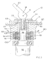
- a cam shaped clamping mechanism is illustrated and designated with the reference numeral 10.
- Clamping mechanism 10 cooperates with a rotary power tool, designated generally with the reference numeral 40, to clamp and hold a disc shaped power tool accessory, here a circular saw blade 60.
- Figs. 8 and 9 depict the rotary power tool 40 as a circular saw tool having a motor 41 with a shaft 44 and incorporating the clamp mechanism 10 and the clutch assembly 80 (described below) of the present invention.
- the particular clamp assembly shown is in the form of a bolt including a threaded shaft 12 and a head 14.
- Shaft 12 threads down into the bore 42 of the power tool output spindle or shaft 44.
- Head 14 is coaxial with the shaft 12 and projects perpendicular to the plane of the blade 60.
- Head 14 is pierced by a pivot pin 16 transverse to the axis of the shaft 12 and includes a flange portion 15 perpendicular to the plane of the blade 60 and axially below the pivot pin.
- cam 18 Pivotably mounted to the pivot pin 16 is a cam 18.
- the peripheral surface 19 of cam 18 has two portions.
- First portion 21 has a first radius r 1 and corresponds to the clamped position of cam 18.
- Second portion 22 has a second radius r 2 , smaller than r 1 , and corresponds to the unclamped position of cam 18.
- a cam lever 20 is connected to cam 18 and projects from it in a line transverse to the pivot pin 16. By means of cam lever 20, the operator may rotate cam 18 from the clamped to the unclamped position.
- a cup-shaped clamp washer 24 Arranged on the head 14 with limited axial mobility and arranged substantially planar parallel to the blade 60 is a cup-shaped clamp washer 24. Clamp washer 24 is captured between the cam 18, which can contact the axially outer surface 26 of the clamp washer 24, and flange 15 of the head 14.
- the cam may be in two parts 18a and 18b, on either side of the head 14.
- the cam lever 20 may be a U shaped piece connected to both cam parts 18a and 18b.
- the clamping mechanism may also include a cam release lever 30.
- Release lever 30 is pivotally connected to pivot pin 16 and has two end portions. First end portion 32 lies underneath cam lever 20 and second end portion 34 is located at the other extremity of release lever 30. Release lever 30 is bent approximately in the location where it connects to pivot pin 16, so that ends 32 and 34 do not lie in the same plane.
- the blade is installed with a central opening 62 coaxial with the bore 42 of the output spindle 44.
- Shaft 12 is inserted through opening 62 and threaded into bore 42, until finger tight.
- Cam 18 should be in the unclamped position and clamp washer 24 is loosely retained between the cam 18 and head flange 15.
- cam lever 20 To clamp the saw blade, the operator presses down (axially inward) on cam lever 20.
- the movement of cam lever 20 causes cam 18 to rotate into the clamped position and moves first portion 21 of peripheral surface 19 into contact against the outer face 26 of the clamp washer 24.
- cam 18 As cam 18 rotates it exerts an increasing compression force onto clamp washer 24, which in turn exerts increasing force onto blade 60.
- cam lever 20 When cam lever 20 is substantially parallel to the plane of blade 60, cam 18 will be positioned so that first portion 21 with radius r 1 is exerting the maximum compressive force on blade 60.
- cam lever 20 drives down first end portion 32 of cam release lever 30 and drives up second end portion 34.
- cam release lever 30 To unlock blade 60, the operator may press down on second end portion 34 of cam release lever 30.
- the cam release lever 30 will pivot around pivot pin 16 and first end portion 32 will move up, thus pushing up against the underside of cam lever 20.
- cam lever 20 As cam lever 20 rotates upward, it will rotate the cam 18.
- Peripheral surface 19 will rotate from first portion 21 to second portion 22 in contact with surface 26 of clamp washer 24, thus releasing the force exerted against the clamp washer.
- a spring washer or, more specifically, a Belleville washer 71 may be inserted between the clamp washer 24 and the saw blade 60.
- the characteristically flat force versus deflection profile of a Belleville washer allows the tool designer to effectively and reproducibly set the compression force which the saw blade 60 will experience, relatively independent of the exact amount of rotation by the cam 18.
- the Belleville washer 71 flattens but the compression force transmitted through it onto the saw blade 60 remains relatively constants.
- the present invention may incorporate a clutch assembly 80, which will transmit more torque to the blade 60 before the onset of slippage.
- clutch assembly 80 a plurality of alternating stacked discs 82 transmit torque between the drive spindle 92 and an inner washer 94.
- the stacked discs 82 consists of at least one each of two types.
- the first type of disc 84 is a generally circular washer keyed to the axially outer end 96 of the spindle 92 at a central opening 85, here shown in the well known "double-D" shape.
- the second type of disc 86 is not keyed to the spindle end 96.
- Second type discs 86 have a central opening 87, here circular, that is freely rotatable around the spindle.
- the outer periphery 88 of the second type discs 86 has radially outward projecting splines 89 with a radius greater than that of the first type discs 84.
- first type discs 84 and second type discs 86 are alternately stacked on the spindle 92.
- the axially outward end 96 of the spindle 92 has a shape that fits into the keyed opening 85 of the first type discs 84.
- the splines 89 of the second type discs 86 are aligned together.
- an inner washer 94 Over the axially outer end 96 of the drive shaft 92 and over the alternating stack of discs 82 is fitted an inner washer 94.
- the inner washer 94 has an internal bore 98 on its axially inner end 100.
- the internal bore 98 has radially inward projecting splines 102.
- the inner splines 102 of the inner washer 94 interlock with the outer splines 89 of the second group discs 86.
- the rotating shaft end 96 directly turns the first group discs 84 keyed to it at their center hole 85.
- the first group discs 84 transmit drive torque to the second group discs 86 by friction contact at their alternating faces.
- the second group discs 86 directly drive the inner washer 94 through their interlocked splines 89 and 102.
- the saw blade 60 is clamped to the axially outer face 95 of the inner washer 94, as previously described, and thus the drive torque is transmitted to it from the inner washer.
- a raised geometric shape 97 (for example a diamond, shown only in cross section) in outer face 95 may be keyed to a matching hole 62 in the saw blade 60. In such an arrangement, slippage must occur at the multiple disc clutch surfaces.
- the clamping assembly 10 may take the general form of a nut, instead of a bolt.
- head 114 has a threaded bore 142 and threads down over a threaded portion 112 of the power tool output spindle 144.
- Head 114 is coaxial with the threaded portion 112 and projects perpendicular to the plane of the blade 60.
- Head 114 is pierced by a pivot pin 116 transverse to the axis of the extension 112 and head 114.
- cam 118 Pivotably mounted to the pivot pin 116 is a cam 118.
- the peripheral surface 119 of cam 118 has two portions.
- First portion 121 has a first radius r 1 and corresponds to the clamped position of cam 18.
- Second portion 122 has a second radius r 2 , smaller than r 1 , and corresponds to the unclamped position of cam 118.
- a cam lever 120 is connected to cam 118 and projects from it in a line transverse to the pivot pin 116. By means of cam lever 120, the operator may rotate cam 118 from the unclamped to the clamped position.
- clamp washer 124 Connected to the head 114 with limited axial mobility and arranged substantially planar parallel to the blade 60 is a clamp washer 124. Clamp washer 124 is captured between the cam 118, which can contact the axially outer surface 126 of the clamp washer 124, and the saw blade 60.
- a saw blade 60 is installed with a central opening 62 coaxial over the shaft extension 112. Head 114 is then threaded onto shaft extension 112, till finger tight. Cam 118 should be in the unclamped position and clamp washer 124 is loosely retained between the cam 118 and head flange 113.
- cam lever 120 To clamp the saw blade 60, the operator presses down on cam lever 120.
- the movement of cam lever 120 causes cam 118 to rotate into the clamped position and moves portion 121 of peripheral surface 119 into contact against the outer face 126 of the clamp washer 124.
- cam 118 rotates it exerts an increasing force onto clamp washer 124, which in turn exerts increasing force onto blade 60.
- cam lever 120 When cam lever 120 is substantially parallel to the plane of blade 60, cam 118 will be positioned so that first portion 121 with diameter d 1 is exerting the maximum compressive force on blade 60.
- cam lever 120 drives down first end portion 132 of cam release lever 130 and second end portion 134 up.
- cam release lever 130 To unlock blade 60, the operator may press down on end portion 134 of cam release lever 130.
- the cam release lever 130 will pivot around pivot pin 116 and first end portion 132 will move up, thus pushing up against the underside of cam lever 120.
- cam lever 120 As cam lever 120 rotates upward, it will rotate the cam 118.
- Peripheral surface 119 will rotate from first portion 121 to second portion 122 in contact with surface 126 of clamp washer 124, thus releasing the force exerted against the clamp washer.
- the operator unthreads the head 114 from the shaft extension 112 with his fingers.
- cam clamping mechanism and clutch assembly may be used individually or together depending on the torque requirements of the particular tool.
Landscapes
- Engineering & Computer Science (AREA)
- Mechanical Engineering (AREA)
- Life Sciences & Earth Sciences (AREA)
- General Engineering & Computer Science (AREA)
- Wood Science & Technology (AREA)
- Forests & Forestry (AREA)
- Constituent Portions Of Griding Lathes, Driving, Sensing And Control (AREA)
- Gripping On Spindles (AREA)
- Holding Or Fastening Of Disk On Rotational Shaft (AREA)
- Mechanical Operated Clutches (AREA)
- Clamps And Clips (AREA)
- Automatic Tool Replacement In Machine Tools (AREA)
- Toys (AREA)
- Milling Processes (AREA)
- Manufacturing Of Magnetic Record Carriers (AREA)
Applications Claiming Priority (4)
| Application Number | Priority Date | Filing Date | Title |
|---|---|---|---|
| US23135300P | 2000-09-08 | 2000-09-08 | |
| US09/948,477 US7013987B2 (en) | 2000-09-08 | 2001-09-07 | Clutch assembly and clamp mechanism for rotary tool disc |
| EP20010307666 EP1250989B1 (de) | 2000-09-08 | 2001-09-10 | Kupplungsanordnung für rotierendes scheibenförmiges Werkzeug |
| EP20050010593 EP1616678B1 (de) | 2000-09-08 | 2001-09-10 | Spannvorrichtung für rotierendes scheibenförmiges Werkzeug |
Related Parent Applications (3)
| Application Number | Title | Priority Date | Filing Date |
|---|---|---|---|
| EP01307666.6 Division | 2001-09-10 | ||
| EP20050010593 Division EP1616678B1 (de) | 2000-09-08 | 2001-09-10 | Spannvorrichtung für rotierendes scheibenförmiges Werkzeug |
| EP05010593.1 Division | 2005-05-17 |
Publications (3)
| Publication Number | Publication Date |
|---|---|
| EP1769893A2 true EP1769893A2 (de) | 2007-04-04 |
| EP1769893A3 EP1769893A3 (de) | 2007-04-18 |
| EP1769893B1 EP1769893B1 (de) | 2012-04-11 |
Family
ID=26925045
Family Applications (3)
| Application Number | Title | Priority Date | Filing Date |
|---|---|---|---|
| EP20050010593 Expired - Lifetime EP1616678B1 (de) | 2000-09-08 | 2001-09-10 | Spannvorrichtung für rotierendes scheibenförmiges Werkzeug |
| EP20070100802 Expired - Lifetime EP1769893B1 (de) | 2000-09-08 | 2001-09-10 | Nockenauslösungshebel für eine Spannvorrichtung für ein rotierendes, scheibenförmiges Werkzeug |
| EP20010307666 Expired - Lifetime EP1250989B1 (de) | 2000-09-08 | 2001-09-10 | Kupplungsanordnung für rotierendes scheibenförmiges Werkzeug |
Family Applications Before (1)
| Application Number | Title | Priority Date | Filing Date |
|---|---|---|---|
| EP20050010593 Expired - Lifetime EP1616678B1 (de) | 2000-09-08 | 2001-09-10 | Spannvorrichtung für rotierendes scheibenförmiges Werkzeug |
Family Applications After (1)
| Application Number | Title | Priority Date | Filing Date |
|---|---|---|---|
| EP20010307666 Expired - Lifetime EP1250989B1 (de) | 2000-09-08 | 2001-09-10 | Kupplungsanordnung für rotierendes scheibenförmiges Werkzeug |
Country Status (6)
| Country | Link |
|---|---|
| US (2) | US7013987B2 (de) |
| EP (3) | EP1616678B1 (de) |
| AT (3) | ATE552951T1 (de) |
| DE (2) | DE60124669T2 (de) |
| DK (1) | DK1250989T3 (de) |
| ES (1) | ES2276748T3 (de) |
Families Citing this family (28)
| Publication number | Priority date | Publication date | Assignee | Title |
|---|---|---|---|---|
| EP1375094A1 (de) * | 2002-06-18 | 2004-01-02 | Black & Decker Inc. | Spannvorrichtung und Kupplungsanordnung für rotierendes scheibenförmiges Werkzeug |
| DE10343753B4 (de) * | 2003-09-22 | 2006-03-30 | Hilti Ag | Selbstsicherndes Schraubelement |
| DE102004020982A1 (de) * | 2004-04-23 | 2005-11-17 | C. & E. Fein Gmbh | Kraftgetriebenes Handwerkzeug mit Spanneinrichtung für ein Werkzeug |
| TWM273437U (en) * | 2004-12-10 | 2005-08-21 | Rexon Ind Corp Ltd | Device for securing saw blade to motor of power tool |
| DE102005052228B4 (de) * | 2005-11-02 | 2010-07-01 | Leica Mikrosysteme Gmbh | Messerhalter für ein Mikrotom mit vibrierendem Messer |
| DE102006021969A1 (de) * | 2006-05-04 | 2007-11-08 | C. & E. Fein Gmbh | Oszillationsantrieb |
| ITBO20060674A1 (it) * | 2006-09-29 | 2008-03-30 | Giben Int Spa | Gruppo lama per macchine sezionatrici di pannelli in legno od assimilabili. |
| JP4964642B2 (ja) * | 2007-03-27 | 2012-07-04 | 株式会社マキタ | 回転刃具の固定装置 |
| DE102007035045A1 (de) * | 2007-07-19 | 2009-01-29 | C. & E. Fein Gmbh | Kraftgetriebenes Handwerkzeug |
| US8230607B2 (en) | 2008-05-09 | 2012-07-31 | Milwaukee Electric Tool Corporation | Keyless blade clamp for a power tool |
| US8857821B2 (en) * | 2008-09-05 | 2014-10-14 | Ati Industrial Automation, Inc. | Manual robotic tool changer with rotating piston |
| DE202009001440U1 (de) * | 2009-01-30 | 2010-07-01 | C. & E. Fein Gmbh | Kraftgetriebenes Handwerkzeug mit Spanneinrichtung für ein Werkzeug |
| US8776657B2 (en) * | 2010-01-26 | 2014-07-15 | Robert Bosch Gmbh | Blade mounting assembly |
| US8899272B2 (en) * | 2010-06-03 | 2014-12-02 | Mark Atkins | Flow restrictor |
| CN102343616A (zh) * | 2010-08-04 | 2012-02-08 | 陈冠文 | 快拆式修边机 |
| DE102011003098A1 (de) * | 2011-01-25 | 2012-07-26 | Robert Bosch Gmbh | Werkzeugspannvorrichtung |
| EP2762276B1 (de) * | 2011-09-29 | 2016-07-27 | Positec Power Tools (Suzhou) Co., Ltd | Multifunktionsmaschine |
| USD682651S1 (en) | 2012-05-14 | 2013-05-21 | Campbell Hausfeld/Scott Fetzer Company | Accessory interface for a tool |
| USD682652S1 (en) | 2012-05-14 | 2013-05-21 | Campbell Hausfeld/Scott Fetzer Company | Tool accessory hub |
| US9339927B2 (en) * | 2012-12-29 | 2016-05-17 | Chervon (Hk) Limited | Accessory clamping mechanism and power tool having the same |
| CN106272269B (zh) * | 2015-06-02 | 2019-01-04 | 南京德朔实业有限公司 | 动力工具 |
| WO2017036403A1 (zh) * | 2015-08-31 | 2017-03-09 | 苏州宝时得电动工具有限公司 | 手持式工具及其夹紧装置 |
| US20170259348A1 (en) * | 2016-03-09 | 2017-09-14 | Ac (Macao Commercial Offshore) Limited | Toolless blade release mechanism for a power tool |
| DE102017214117B4 (de) * | 2017-08-11 | 2026-02-26 | Robert Bosch Gmbh | Schnellspannvorrichtung |
| CN111761480B (zh) * | 2020-03-30 | 2021-10-29 | 浙江博来工具有限公司 | 一种快速夹紧装置及具有快速夹紧装置的角磨机 |
| US11560909B2 (en) * | 2021-05-03 | 2023-01-24 | GM Global Technology Operations LLC | Accessory attachment mechanism |
| CN114290022A (zh) * | 2021-12-30 | 2022-04-08 | 杭州电子科技大学 | 发动机进排气轴密封圈装配的工装定位夹紧运输机构 |
| CN116532193B (zh) * | 2023-05-18 | 2024-03-08 | 山东辰沃智能科技有限公司 | 一种手工石磨 |
Family Cites Families (56)
| Publication number | Priority date | Publication date | Assignee | Title |
|---|---|---|---|---|
| DE192319C (de) * | ||||
| US499113A (en) * | 1893-06-06 | Traveling thrasher | ||
| US1286799A (en) * | 1918-08-30 | 1918-12-03 | Otto Schuler | Device for hanging circular saws. |
| US2430677A (en) * | 1945-04-17 | 1947-11-11 | Leo G Hobart | Clamp |
| US2726524A (en) * | 1953-09-23 | 1955-12-13 | Paul X Gorin | Friction drive coupling with overload slip |
| US2803103A (en) * | 1955-09-14 | 1957-08-20 | Oscar G Kollman | Drive shaft connection assembly for rotary power mower |
| US3396557A (en) * | 1966-08-19 | 1968-08-13 | Black & Decker Mfg Co | Adjustable slip clutch for rotary tools |
| US3440915A (en) * | 1967-02-28 | 1969-04-29 | Bliss Co | Quick release connection |
| DE1936720A1 (de) * | 1969-07-18 | 1971-02-04 | Heinrich Schaller Fa | Elastisches Schnellwechselfutter fuer hochtourige Schleifscheiben |
| US3656393A (en) * | 1970-06-19 | 1972-04-18 | Paramount Textile Mach Co | Carbide saw blade locking device |
| CH527014A (de) * | 1970-08-07 | 1972-08-31 | Meyer & Burger Ag Maschf | Spannvorrichtung für ein Innen-Trennsägeblatt |
| US3705611A (en) * | 1970-12-16 | 1972-12-12 | Minoru Sakamoto | Circular saw and attachment therefor |
| DE2320919C2 (de) * | 1973-04-25 | 1991-06-20 | Ledermann Gmbh + Co, 7240 Horb | Schnellwechsel-Spannvorrichtung für Rotationswerkzeuge, insbesondere für Kreissägen |
| US4205572A (en) * | 1978-08-29 | 1980-06-03 | Weiner Robert I | Saw blade retainer and kickback clutch assembly |
| US4297921A (en) * | 1979-08-10 | 1981-11-03 | Wally Wydra | Circular saw blade removing combination |
| DE2941358A1 (de) * | 1979-10-12 | 1981-04-23 | Robert Bosch Gmbh, 7000 Stuttgart | Befestigungsvorrichtung fuer ein kreissaegeblatt auf einem antriebszapfen |
| JPS5849436B2 (ja) * | 1980-08-06 | 1983-11-04 | マエダ工業株式会社 | 自転車用クイツクレリ−ズハブ |
| US4339893A (en) * | 1980-10-09 | 1982-07-20 | The Warner & Swasey Company | Quick release hub assembly |
| US4434586A (en) * | 1980-12-03 | 1984-03-06 | Robert Bosch Gmbh | Machine tool, especially a hand-held power tool with a turnable clamping element for clamping a tool on the tool spindle |
| DE3105265C2 (de) * | 1981-02-13 | 1983-05-05 | Gerhard 7737 Bad Dürrheim Steidle | Mechanisch geschaltete, insbesondere manuell betäti gbare Lamellen-Kupplung |
| US4525097A (en) * | 1981-04-23 | 1985-06-25 | Ziegelmeyer Harold R | Force multiplying locking arrangement |
| JPS57171601U (de) * | 1981-04-24 | 1982-10-28 | ||
| US4513633A (en) * | 1982-04-08 | 1985-04-30 | Eaton Corporation | Positive drive and generated cam surfaces therefor |
| US4550817A (en) * | 1984-02-29 | 1985-11-05 | Lambert Brake Corporation | Mechanical clutch |
| US4547997A (en) * | 1984-05-11 | 1985-10-22 | Cincinnati Milacron Inc. | Adjustable tool mount |
| US4657428A (en) * | 1985-09-10 | 1987-04-14 | Wiley Edward R | Quick change mechanism for circular saw blades and other spinning disc devices |
| DE3623555A1 (de) * | 1986-07-12 | 1988-02-04 | Fein C & E | Befestigungseinrichtung fuer scheibenfoermige werkzeuge an der werkzeugspindel einer tragbaren elektrowerkzeugmaschine |
| US4730952A (en) * | 1986-08-04 | 1988-03-15 | Wiley Edward R | Quick change mechanism for circular saw blades |
| DE3643067A1 (de) * | 1986-12-17 | 1988-06-23 | Bosch Gmbh Robert | Spanneinrichtung zum axialen festspannen eines werkzeuges, insbesondere einer scheibe |
| US4729193A (en) * | 1986-12-22 | 1988-03-08 | Eugene Gant | Cutting disk mounting assembly |
| DE3644444A1 (de) * | 1986-12-24 | 1988-07-07 | Pav Praezisions Apparatebau Ag | Messkluppe |
| DE3644441A1 (de) * | 1986-12-24 | 1988-07-07 | Bosch Gmbh Robert | Spanneinrichtung zum loesbaren befestigen eines werkzeuges, insbesondere einer scheibe |
| DE3702142C2 (de) * | 1987-01-24 | 1995-09-21 | Bosch Gmbh Robert | Spanneinrichtung zum axialen Festspannen eines Werkzeuges, insbesondere eines als Scheibe ausgestalteten spanenden Werkzeuges |
| DE3721470A1 (de) * | 1987-06-30 | 1989-01-12 | Eisele Maschf Chr | Vorrichtung zum einspannen eines kreissaegeblattes |
| DE3741484C1 (de) * | 1987-12-08 | 1989-08-24 | Fein C & E | Handwerkzeugmaschine mit automatischer Arretierung der Arbeitsspindel |
| DE3902874A1 (de) * | 1989-02-01 | 1990-08-09 | Fein C & E | Adapter zum befestigen eines zusatzwerkzeugs |
| US4977802A (en) * | 1989-08-09 | 1990-12-18 | Eberhard Kirbach | Self aligning guides for circular saws |
| US5156508A (en) * | 1989-12-27 | 1992-10-20 | Grisley Kenneth M | Cam action clamp |
| NZ239780A (en) * | 1990-09-12 | 1995-10-26 | Norman Leslie Matthews | Reduced friction fastener; low friction material between threaded hub and thrust disc |
| DE59101383D1 (de) * | 1991-01-16 | 1994-05-19 | Fein C & E | Tragbare Schleifmaschine mit Schnellspanneinrichtung. |
| US5158331A (en) * | 1991-02-25 | 1992-10-27 | The United States Of America As Represented By The Administrator Of The National Aeronautics And Space Administration | Preloaded latching device |
| DE9104431U1 (de) * | 1991-04-11 | 1991-08-22 | K.W. Hochschorner GmbH, 8033 Martinsried | Schnellspanner für ein Fahrrad |
| JP3244718B2 (ja) * | 1991-05-22 | 2002-01-07 | 株式会社マキタ | 回転工具における回転刃具の固止装置 |
| GB9218366D0 (en) * | 1992-08-28 | 1992-10-14 | Black & Decker Inc | A locking device |
| FR2698032B1 (fr) * | 1992-11-16 | 1995-10-06 | Metabowerke Gmbh | Dispositif de serrage rapide destine au serrage axial d'un outil en forme de disque. |
| US5351578A (en) * | 1992-11-20 | 1994-10-04 | James Emter | Resilient compressible clamping surface for circular saw blades |
| US5567100A (en) * | 1993-03-15 | 1996-10-22 | Power Tool Holders Incorporated | Torque enhancing clamping nut |
| JPH0727121A (ja) * | 1993-06-30 | 1995-01-27 | Jacobs Japan Inc | 締付け用ネジ |
| DE4336620C2 (de) * | 1993-10-27 | 1997-07-03 | Fein C & E | Elektrowerkzeug mit einer nur bei ausgeschaltetem Motor betätigbaren Spannvorrichtung |
| US5689891A (en) * | 1994-12-13 | 1997-11-25 | Milwaukee Electric Tool Corp. | Clutch mechanism for reciprocating saws |
| DE19649514A1 (de) * | 1996-11-29 | 1998-06-04 | Bosch Gmbh Robert | Handwerkzeugmaschine |
| US6004064A (en) * | 1998-06-06 | 1999-12-21 | Franz; Patrick J. | Retrofittable quick release mechanism |
| DE29820693U1 (de) * | 1998-11-19 | 2000-03-30 | Robert Bosch Gmbh, 70469 Stuttgart | Spanneinrichtung zum axialen Festspannen eines scheibenförmigen Werkzeuges |
| US6439091B1 (en) * | 1999-04-19 | 2002-08-27 | Black & Decker Inc. | Clutch mechanism |
| US6295910B1 (en) * | 1999-08-13 | 2001-10-02 | S-B Power Tool Company | Clutch assembly for use with a circular saw |
| FR2805013B1 (fr) * | 2000-02-16 | 2003-01-10 | Diamant Boart Sa | Ecrou de serrage et de blocage d'un outil, tel qu'un disque d'une machine d'usinage sur l'arbre de ladite machine |
-
2001
- 2001-09-07 US US09/948,477 patent/US7013987B2/en not_active Expired - Lifetime
- 2001-09-10 AT AT07100802T patent/ATE552951T1/de active
- 2001-09-10 AT AT01307666T patent/ATE345910T1/de not_active IP Right Cessation
- 2001-09-10 ES ES01307666T patent/ES2276748T3/es not_active Expired - Lifetime
- 2001-09-10 EP EP20050010593 patent/EP1616678B1/de not_active Expired - Lifetime
- 2001-09-10 EP EP20070100802 patent/EP1769893B1/de not_active Expired - Lifetime
- 2001-09-10 DK DK01307666T patent/DK1250989T3/da active
- 2001-09-10 EP EP20010307666 patent/EP1250989B1/de not_active Expired - Lifetime
- 2001-09-10 DE DE2001624669 patent/DE60124669T2/de not_active Expired - Lifetime
- 2001-09-10 AT AT05010593T patent/ATE395171T1/de not_active IP Right Cessation
- 2001-09-10 DE DE60134061T patent/DE60134061D1/de not_active Expired - Lifetime
-
2006
- 2006-02-17 US US11/356,835 patent/US20070007025A1/en not_active Abandoned
Also Published As
| Publication number | Publication date |
|---|---|
| EP1769893B1 (de) | 2012-04-11 |
| ATE345910T1 (de) | 2006-12-15 |
| DE60124669T2 (de) | 2007-09-13 |
| ATE395171T1 (de) | 2008-05-15 |
| EP1250989B1 (de) | 2006-11-22 |
| DE60124669D1 (de) | 2007-01-04 |
| DK1250989T3 (da) | 2007-04-02 |
| EP1616678B1 (de) | 2008-05-14 |
| EP1616678A1 (de) | 2006-01-18 |
| US20020030328A1 (en) | 2002-03-14 |
| EP1250989A2 (de) | 2002-10-23 |
| EP1769893A3 (de) | 2007-04-18 |
| ES2276748T3 (es) | 2007-07-01 |
| US7013987B2 (en) | 2006-03-21 |
| DE60134061D1 (de) | 2008-06-26 |
| EP1250989A3 (de) | 2004-01-07 |
| US20070007025A1 (en) | 2007-01-11 |
| ATE552951T1 (de) | 2012-04-15 |
Similar Documents
| Publication | Publication Date | Title |
|---|---|---|
| US7013987B2 (en) | Clutch assembly and clamp mechanism for rotary tool disc | |
| US11045919B2 (en) | Power tool | |
| US6305481B1 (en) | Clutch mechanism for use in a power-driven tool | |
| JP3091488B2 (ja) | 締付け具 | |
| US7481608B2 (en) | Rotatable chuck | |
| US5947671A (en) | Hand actuable clamping device with circumferentially extending tightening members | |
| CN1211176C (zh) | 手持式工具机 | |
| US7478979B2 (en) | Rotatable chuck | |
| US20080014844A1 (en) | Power tool with spindle lock | |
| JPH02501813A (ja) | 工具、殊に円板形工具を軸方向で不動に締付けるための締付装置 | |
| EP1375094A1 (de) | Spannvorrichtung und Kupplungsanordnung für rotierendes scheibenförmiges Werkzeug | |
| US6645058B2 (en) | Clamp mechanism for rotary tool disc | |
| US5584753A (en) | Device for fixing tool element to rotary tool | |
| JPH02501128A (ja) | 工具、殊に円板形工具を着脱可能に固定するためのチヤツク装置 | |
| US4901479A (en) | Portable hand machine tool, particularly angle gringer | |
| US20110039482A1 (en) | Grinder | |
| US20250339938A1 (en) | Ratcheting tool with clutch | |
| EP3300835B1 (de) | Zubehörklemme und spindelverriegelungsmechanismus für elektrowerkzeugschloss | |
| KR20200088230A (ko) | 스프링 장착식 조절 가능한 헤드 | |
| EP3456472B1 (de) | Oszillierendes werkzeug | |
| CN1997487A (zh) | 快速夹紧装置 | |
| EP0349588A1 (de) | Universalunterlegscheibe. | |
| EP4046750B1 (de) | Bandschleifmaschine |
Legal Events
| Date | Code | Title | Description |
|---|---|---|---|
| PUAI | Public reference made under article 153(3) epc to a published international application that has entered the european phase |
Free format text: ORIGINAL CODE: 0009012 |
|
| PUAL | Search report despatched |
Free format text: ORIGINAL CODE: 0009013 |
|
| 17P | Request for examination filed |
Effective date: 20070119 |
|
| AC | Divisional application: reference to earlier application |
Ref document number: 1250989 Country of ref document: EP Kind code of ref document: P Ref document number: 1616678 Country of ref document: EP Kind code of ref document: P |
|
| AK | Designated contracting states |
Kind code of ref document: A2 Designated state(s): AT BE BG CH CY CZ DE DK EE ES FI FR GB GR HU IE IS IT LI LT LU LV MC NL PL PT RO SE SI SK TR |
|
| AX | Request for extension of the european patent |
Extension state: AL BA HR MK YU |
|
| AK | Designated contracting states |
Kind code of ref document: A3 Designated state(s): AT BE BG CH CY CZ DE DK EE ES FI FR GB GR HU IE IS IT LI LT LU LV MC NL PL PT RO SE SI SK TR |
|
| AX | Request for extension of the european patent |
Extension state: AL BA HR MK YU |
|
| AKX | Designation fees paid |
Designated state(s): AT BE BG CH CY DE DK ES FI FR GB IE IT LI LU MC NL PL SE TR |
|
| RBV | Designated contracting states (corrected) |
Designated state(s): AT BE CH CY DE DK ES FI FR GB GR IE IT LI LU MC NL PT SE TR |
|
| GRAP | Despatch of communication of intention to grant a patent |
Free format text: ORIGINAL CODE: EPIDOSNIGR1 |
|
| RIN1 | Information on inventor provided before grant (corrected) |
Inventor name: NOCK, STEFAN Inventor name: O'BANION, MICHAEL |
|
| GRAS | Grant fee paid |
Free format text: ORIGINAL CODE: EPIDOSNIGR3 |
|
| GRAA | (expected) grant |
Free format text: ORIGINAL CODE: 0009210 |
|
| AC | Divisional application: reference to earlier application |
Ref document number: 1616678 Country of ref document: EP Kind code of ref document: P Ref document number: 1250989 Country of ref document: EP Kind code of ref document: P |
|
| AK | Designated contracting states |
Kind code of ref document: B1 Designated state(s): AT BE CH CY DE DK ES FI FR GB GR IE IT LI LU MC NL PT SE TR |
|
| REG | Reference to a national code |
Ref country code: GB Ref legal event code: FG4D |
|
| REG | Reference to a national code |
Ref country code: CH Ref legal event code: EP |
|
| REG | Reference to a national code |
Ref country code: AT Ref legal event code: REF Ref document number: 552951 Country of ref document: AT Kind code of ref document: T Effective date: 20120415 |
|
| REG | Reference to a national code |
Ref country code: IE Ref legal event code: FG4D |
|
| REG | Reference to a national code |
Ref country code: DE Ref legal event code: R096 Ref document number: 60146411 Country of ref document: DE Effective date: 20120606 |
|
| REG | Reference to a national code |
Ref country code: NL Ref legal event code: VDEP Effective date: 20120411 |
|
| REG | Reference to a national code |
Ref country code: AT Ref legal event code: MK05 Ref document number: 552951 Country of ref document: AT Kind code of ref document: T Effective date: 20120411 |
|
| PG25 | Lapsed in a contracting state [announced via postgrant information from national office to epo] |
Ref country code: FI Free format text: LAPSE BECAUSE OF FAILURE TO SUBMIT A TRANSLATION OF THE DESCRIPTION OR TO PAY THE FEE WITHIN THE PRESCRIBED TIME-LIMIT Effective date: 20120411 Ref country code: SE Free format text: LAPSE BECAUSE OF FAILURE TO SUBMIT A TRANSLATION OF THE DESCRIPTION OR TO PAY THE FEE WITHIN THE PRESCRIBED TIME-LIMIT Effective date: 20120411 Ref country code: CY Free format text: LAPSE BECAUSE OF FAILURE TO SUBMIT A TRANSLATION OF THE DESCRIPTION OR TO PAY THE FEE WITHIN THE PRESCRIBED TIME-LIMIT Effective date: 20120411 |
|
| PG25 | Lapsed in a contracting state [announced via postgrant information from national office to epo] |
Ref country code: GR Free format text: LAPSE BECAUSE OF FAILURE TO SUBMIT A TRANSLATION OF THE DESCRIPTION OR TO PAY THE FEE WITHIN THE PRESCRIBED TIME-LIMIT Effective date: 20120712 Ref country code: PT Free format text: LAPSE BECAUSE OF FAILURE TO SUBMIT A TRANSLATION OF THE DESCRIPTION OR TO PAY THE FEE WITHIN THE PRESCRIBED TIME-LIMIT Effective date: 20120813 |
|
| PG25 | Lapsed in a contracting state [announced via postgrant information from national office to epo] |
Ref country code: BE Free format text: LAPSE BECAUSE OF FAILURE TO SUBMIT A TRANSLATION OF THE DESCRIPTION OR TO PAY THE FEE WITHIN THE PRESCRIBED TIME-LIMIT Effective date: 20120411 |
|
| PG25 | Lapsed in a contracting state [announced via postgrant information from national office to epo] |
Ref country code: NL Free format text: LAPSE BECAUSE OF FAILURE TO SUBMIT A TRANSLATION OF THE DESCRIPTION OR TO PAY THE FEE WITHIN THE PRESCRIBED TIME-LIMIT Effective date: 20120411 Ref country code: DK Free format text: LAPSE BECAUSE OF FAILURE TO SUBMIT A TRANSLATION OF THE DESCRIPTION OR TO PAY THE FEE WITHIN THE PRESCRIBED TIME-LIMIT Effective date: 20120411 Ref country code: AT Free format text: LAPSE BECAUSE OF FAILURE TO SUBMIT A TRANSLATION OF THE DESCRIPTION OR TO PAY THE FEE WITHIN THE PRESCRIBED TIME-LIMIT Effective date: 20120411 |
|
| PLBE | No opposition filed within time limit |
Free format text: ORIGINAL CODE: 0009261 |
|
| STAA | Information on the status of an ep patent application or granted ep patent |
Free format text: STATUS: NO OPPOSITION FILED WITHIN TIME LIMIT |
|
| PG25 | Lapsed in a contracting state [announced via postgrant information from national office to epo] |
Ref country code: IT Free format text: LAPSE BECAUSE OF FAILURE TO SUBMIT A TRANSLATION OF THE DESCRIPTION OR TO PAY THE FEE WITHIN THE PRESCRIBED TIME-LIMIT Effective date: 20120411 |
|
| 26N | No opposition filed |
Effective date: 20130114 |
|
| PG25 | Lapsed in a contracting state [announced via postgrant information from national office to epo] |
Ref country code: MC Free format text: LAPSE BECAUSE OF NON-PAYMENT OF DUE FEES Effective date: 20120930 Ref country code: ES Free format text: LAPSE BECAUSE OF FAILURE TO SUBMIT A TRANSLATION OF THE DESCRIPTION OR TO PAY THE FEE WITHIN THE PRESCRIBED TIME-LIMIT Effective date: 20120722 |
|
| REG | Reference to a national code |
Ref country code: CH Ref legal event code: PL |
|
| REG | Reference to a national code |
Ref country code: DE Ref legal event code: R097 Ref document number: 60146411 Country of ref document: DE Effective date: 20130114 |
|
| REG | Reference to a national code |
Ref country code: IE Ref legal event code: MM4A |
|
| REG | Reference to a national code |
Ref country code: FR Ref legal event code: ST Effective date: 20130531 |
|
| PG25 | Lapsed in a contracting state [announced via postgrant information from national office to epo] |
Ref country code: LI Free format text: LAPSE BECAUSE OF NON-PAYMENT OF DUE FEES Effective date: 20120930 Ref country code: IE Free format text: LAPSE BECAUSE OF NON-PAYMENT OF DUE FEES Effective date: 20120910 Ref country code: CH Free format text: LAPSE BECAUSE OF NON-PAYMENT OF DUE FEES Effective date: 20120930 |
|
| PG25 | Lapsed in a contracting state [announced via postgrant information from national office to epo] |
Ref country code: FR Free format text: LAPSE BECAUSE OF NON-PAYMENT OF DUE FEES Effective date: 20121001 |
|
| PG25 | Lapsed in a contracting state [announced via postgrant information from national office to epo] |
Ref country code: TR Free format text: LAPSE BECAUSE OF FAILURE TO SUBMIT A TRANSLATION OF THE DESCRIPTION OR TO PAY THE FEE WITHIN THE PRESCRIBED TIME-LIMIT Effective date: 20120411 |
|
| PG25 | Lapsed in a contracting state [announced via postgrant information from national office to epo] |
Ref country code: LU Free format text: LAPSE BECAUSE OF NON-PAYMENT OF DUE FEES Effective date: 20120910 |
|
| PGFP | Annual fee paid to national office [announced via postgrant information from national office to epo] |
Ref country code: GB Payment date: 20140929 Year of fee payment: 14 |
|
| PGFP | Annual fee paid to national office [announced via postgrant information from national office to epo] |
Ref country code: DE Payment date: 20140929 Year of fee payment: 14 |
|
| REG | Reference to a national code |
Ref country code: DE Ref legal event code: R119 Ref document number: 60146411 Country of ref document: DE |
|
| GBPC | Gb: european patent ceased through non-payment of renewal fee |
Effective date: 20150910 |
|
| PG25 | Lapsed in a contracting state [announced via postgrant information from national office to epo] |
Ref country code: DE Free format text: LAPSE BECAUSE OF NON-PAYMENT OF DUE FEES Effective date: 20160401 Ref country code: GB Free format text: LAPSE BECAUSE OF NON-PAYMENT OF DUE FEES Effective date: 20150910 |