EP1769926B1 - Tête et imprimante à jet d'encre - Google Patents
Tête et imprimante à jet d'encre Download PDFInfo
- Publication number
- EP1769926B1 EP1769926B1 EP06020313A EP06020313A EP1769926B1 EP 1769926 B1 EP1769926 B1 EP 1769926B1 EP 06020313 A EP06020313 A EP 06020313A EP 06020313 A EP06020313 A EP 06020313A EP 1769926 B1 EP1769926 B1 EP 1769926B1
- Authority
- EP
- European Patent Office
- Prior art keywords
- ink
- nozzle
- nozzles
- nozzle row
- jet
- Prior art date
- Legal status (The legal status is an assumption and is not a legal conclusion. Google has not performed a legal analysis and makes no representation as to the accuracy of the status listed.)
- Not-in-force
Links
Images






Classifications
-
- B—PERFORMING OPERATIONS; TRANSPORTING
- B41—PRINTING; LINING MACHINES; TYPEWRITERS; STAMPS
- B41J—TYPEWRITERS; SELECTIVE PRINTING MECHANISMS, i.e. MECHANISMS PRINTING OTHERWISE THAN FROM A FORME; CORRECTION OF TYPOGRAPHICAL ERRORS
- B41J2/00—Typewriters or selective printing mechanisms characterised by the printing or marking process for which they are designed
- B41J2/005—Typewriters or selective printing mechanisms characterised by the printing or marking process for which they are designed characterised by bringing liquid or particles selectively into contact with a printing material
- B41J2/01—Ink jet
- B41J2/135—Nozzles
- B41J2/145—Arrangement thereof
-
- B—PERFORMING OPERATIONS; TRANSPORTING
- B41—PRINTING; LINING MACHINES; TYPEWRITERS; STAMPS
- B41J—TYPEWRITERS; SELECTIVE PRINTING MECHANISMS, i.e. MECHANISMS PRINTING OTHERWISE THAN FROM A FORME; CORRECTION OF TYPOGRAPHICAL ERRORS
- B41J2/00—Typewriters or selective printing mechanisms characterised by the printing or marking process for which they are designed
- B41J2/005—Typewriters or selective printing mechanisms characterised by the printing or marking process for which they are designed characterised by bringing liquid or particles selectively into contact with a printing material
- B41J2/01—Ink jet
- B41J2/21—Ink jet for multi-colour printing
- B41J2/2103—Features not dealing with the colouring process per se, e.g. construction of printers or heads, driving circuit adaptations
-
- B—PERFORMING OPERATIONS; TRANSPORTING
- B41—PRINTING; LINING MACHINES; TYPEWRITERS; STAMPS
- B41J—TYPEWRITERS; SELECTIVE PRINTING MECHANISMS, i.e. MECHANISMS PRINTING OTHERWISE THAN FROM A FORME; CORRECTION OF TYPOGRAPHICAL ERRORS
- B41J2/00—Typewriters or selective printing mechanisms characterised by the printing or marking process for which they are designed
- B41J2/005—Typewriters or selective printing mechanisms characterised by the printing or marking process for which they are designed characterised by bringing liquid or particles selectively into contact with a printing material
- B41J2/01—Ink jet
- B41J2/135—Nozzles
- B41J2/14—Structure thereof only for on-demand ink jet heads
- B41J2002/14459—Matrix arrangement of the pressure chambers
-
- Y—GENERAL TAGGING OF NEW TECHNOLOGICAL DEVELOPMENTS; GENERAL TAGGING OF CROSS-SECTIONAL TECHNOLOGIES SPANNING OVER SEVERAL SECTIONS OF THE IPC; TECHNICAL SUBJECTS COVERED BY FORMER USPC CROSS-REFERENCE ART COLLECTIONS [XRACs] AND DIGESTS
- Y10—TECHNICAL SUBJECTS COVERED BY FORMER USPC
- Y10T—TECHNICAL SUBJECTS COVERED BY FORMER US CLASSIFICATION
- Y10T29/00—Metal working
- Y10T29/42—Piezoelectric device making
-
- Y—GENERAL TAGGING OF NEW TECHNOLOGICAL DEVELOPMENTS; GENERAL TAGGING OF CROSS-SECTIONAL TECHNOLOGIES SPANNING OVER SEVERAL SECTIONS OF THE IPC; TECHNICAL SUBJECTS COVERED BY FORMER USPC CROSS-REFERENCE ART COLLECTIONS [XRACs] AND DIGESTS
- Y10—TECHNICAL SUBJECTS COVERED BY FORMER USPC
- Y10T—TECHNICAL SUBJECTS COVERED BY FORMER US CLASSIFICATION
- Y10T29/00—Metal working
- Y10T29/49—Method of mechanical manufacture
- Y10T29/49401—Fluid pattern dispersing device making, e.g., ink jet
Definitions
- the present invention relates to an ink-jet head which jets an ink on to a recording medium, and an ink-j et printer.
- a color ink-jet printer which records a color image by jetting inks of plurality of colors onto a recording medium includes an ink-jet printer which is capable of jetting a black ink and a color ink and which has hitherto been use, and an ink-jet printer which is capable of jetting inks other than black and color inks.
- an ink-jet printer which is capable of jetting a special color ink for example, gold and silver ink, white ink, transparent ink, a fluorescent ink, or the like
- 6024431 , 6142619 , and 2002024549A1 (correspond to Japanese Patent Application Laid-open No. H6-246909 ), include a plurality of recording heads (ink-jet heads) mounted on one holder which is capable of moving in a predetermined direction, and each of these recording heads includes nozzles which jet an extended-color ink such as a light color ink, a color ink, black ink and a special color ink.
- the recording heads are arranged (lined up) in a direction of movement of the head holder (scanning direction) in an order of a recording head for the color ink, a recording head for the black ink, a recording head for special color ink, and a recording head for the extended-color ink.
- a recording head for a special color ink in addition to a recording head for a black ink and a recording head for a color ink, is mounted on one head holder, a length of the head holder in a scanning direction becomes long, and this increase in the length of the recording head leads to an increase in a size of an overall printer.
- the recording head for the special color ink is positioned between the recording head for the black ink and a recording head for an extended-ink, the special color ink jetted from the head for the special color ink easily makes inflow into other nozzles positioned at both sides of the recording head.
- the special color ink has a poor dispersibility, such as a gold ink, a silver ink, or a white ink which includes fine particles having a high specific gravity
- a precipitate is generated inside the nozzle, which may lead to a jetting defect such as blocking of the nozzle etc., in a nozzle which jets an ink other than the special color ink.
- An object of the present invention is to provide an ink-jet head and an ink-j et printer which are capable of jetting the special color ink, and reducing a size of a printer, and further, capable of suppressing mixing of the special color ink in a nozzle which jets an ink of other type.
- an ink-jet head which jets an ink, comprising:
- the first nozzle row, the second nozzle row, and the third nozzle row are aligned in a second direction which intersects with the first direction, and the third nozzle row is arranged at an end with respect to the second direction.
- the ink-jet head includes the first nozzle row which jets the black ink, the second nozzle row which jets the color ink, and the third nozzle row which jets the special color ink, it is possible to jet by one ink-jet head, the special color ink which does not contribute to a full color printing, in addition to the black ink and the color ink. Consequently, it is possible to deal with a printing of various images.
- the special color ink for example, inks which do not contribute to a full color printing such as an ink which diffuses an aroma, or a gold ink and a silver ink, a white ink, a transparent ink, and a fluorescent ink, and special inks which react to ultraviolet rays and magnetism, are appropriate.
- Light color inks which contribute to the full color printing, such as light cyan and light magenta are not included in the special color inks.
- it is possible to narrow an interval between rows of nozzles, as compared to a case in which a recording head is provided for each type of ink it is possible to reduce a size of the overall printer.
- the third nozzle row which jets the special color ink is positioned at an extreme end with respect to the second direction, it is possible to suppress an occurrence of a jetting defect in a nozzle caused due to flowing of the special color ink into a nozzle which jets an ink of other type.
- the third nozzle row which jets the special color ink is positioned at the extreme end with respect to the second direction.
- the third nozzle row may be positioned next to the first nozzle row.
- the black ink is let to be jetted not only from the first nozzles which jet the black ink, but also from the third nozzles in the third nozzle row, instead of the special color ink, the number of nozzles jetting the black ink is increased. Consequently, it is possible to increase a printing speed than a speed in a case of performing monochrome printing by only the firstnozzles. Since the third nozzle row is positioned adj acent to the first nozzle row which jet the black ink, it is possible to supply easily the black ink to both the first nozzles and the third nozzles.
- the first direction may be orthogonal to the second direction. In this case, it is possible to suppress to a substantial extent an increase in a length of the ink-jet head with respect to the second direction, which is caused due to providing the third nozzle row which jet the special color ink.
- the first nozzle row includes two first nozzle sub arrays each having a predetermined number of the first nozzles arranged in the first direction at the pitch P, and the two first nozzle sub arrays are positioned to be mutually shifted by P/2, in the first direction;
- the second nozzle row includes a plurality of second nozzle sub arrays each having the predetermined number of the second nozzles arranged in the first direction at the pitch P, the second nozzles belonging to each of the second nozzle sub arrays are positioned at a same position with respect to the first direction, and the color ink includes a plurality of sub color inks which are mutually different in color and each of which is jetted from second nozzles belonging to one of the second nozzle sub arrays;
- the third nozzle row includes two third nozzle sub arrays having a predetermined number of third nozzles arranged in the first direction at the pitch P, and the two third nozzle sub arrays are positioned to be mutually shifted by P/2, in the first direction
- An interval between the nozzles (a pitch of the nozzles) with respect to the first direction of the first nozzle row which jets the black ink, and the third nozzle row which jets the special color ink is 1/2 of the pitch P of each row of nozzle. Therefore, the printing speed at the time of performing the printing by the black ink and the special color ink is increased. Furthermore, when the black ink is let to be jetted instead of the special color ink from the third nozzle row, the pitch of the nozzles jetting the black ink becomes 1/4 of the pitch P of each row of nozzle, and the printing speed at the time of monochrome printing is increased.
- the special color ink may be an ink which is selected from a group consisting of a gold ink, a silver ink, a white ink, a transparent ink, an aromatic ink, a fluorescent ink, an ultraviolet fluorescent ink, and a magnetic ink.
- a gold ink a gold ink
- a silver ink a white ink
- a transparent ink an aromatic ink
- a fluorescent ink a fluorescent ink
- an ultraviolet fluorescent ink an ink which reacts to ultraviolet rays and emits fluorescence
- the magnetic ink is an ink which includes a powder of a magnetic material, and reacts to a magnetic field.
- an ink-jet printer which includes the ink-jet head of the present invention is provided.
- the ink-jet printer of the present invention it is possible jet further from one ink-jet head, the special color ink which does not contribute to the color printing, in addition to the black ink and the color ink. Therefore, the ink-jet printer of the present invention is capable to deal with printing of various images.
- the recording heads are provided according to the type of ink, it is possible to reduce the size of the printer by narrowing an interval between rows of nozzles.
- the ink-jet head may include an ink jetting surface in which ejecting ports of the first nozzles, the second nozzles, and the third nozzles are formed; the ink-jet printer may further include a wiper which is movable relative to the ink jetting surface in the second direction, and wipes the ink adhered to the ink jetting surface; and the third nozzle row may be positioned at a farthermost downstream side with respect to a direction in which the wiper moves while wiping the ink jetting surface.
- a special color ink which cannot be checked visually such as an ink which emits fluorescence upon reacting to the ultraviolet rays, or the magnetic ink
- the special color ink is an ink having a poor dispersibility, such as the white color ink, the gold ink, and the silver ink, which includes fine particles having a high specific gravity
- the special color ink is flowed into a nozzle which jets an ink of other type, it causes blocking of the nozzle.
- the third nozzle row is positioned at the extreme downstream side with respect to the direction of movement of the wiper while wiping the ink jetting surface, an area near ejecting ports of the third nozzles in the ink jetting surface is wiped at the last. Therefore, it is possible to suppress the special color ink which has adhered to the ink jetting surface, from being flowed into a nozzle which jets other ink at the time of wiping.
- the ink-jet printer of the present invention may further include a maintenance mechanism which maintain the inkjet head, the maintenance mechanism including a cap which covers the ink-jet head, a suction mechanism which sucks the ink through the cap, and a wiper having flexibility.
- the ink-jet printer includes the maintenance mechanism which performs maintenance such as performing a purge operation when there is a blockage of nozzle, or wiping ink etc. which is adhered near a nozzle of the ink-jet head, it is possible to maintain an ink-jetting condition of the ink-jet head to be satisfactory.
- the present invention is applied to a color ink-jet printer which jets inks of four colors (cyan, magenta, yellow, and black) from nozzles, on to a recording paper.
- the ink-jet printer 100 includes a carriage 5 which is movable in a left and right direction in Fig. 1 , an ink-jet head 1 of serial type which is provided on the carriage 5, and jets the ink on to a recording paper 7, and transporting rollers 6 which transport the recording paper 7 in a forward direction.
- the ink-jet head 1 is connected to five ink cartridges 8a to 8e via tubes 22.
- a black ink is stored in the ink cartridge 8b, and color inks of three colors cyan, magenta, and yellow respectively are stored in the three ink cartridges 8c to 8e.
- a special color ink is stored in the ink cartridge 8a.
- the special color ink is an ink other than the black ink and the color inks, and the special color ink corresponds to an inkwhich do not contribute to a formation of a full color image such as an ink which diffuses an aroma, or a gold ink and a silver ink, a white color ink, a transparent ink, and a fluorescent ink, and a special ink which reacts to ultraviolet rays or magnetism.
- the special color inks do not include so called light color inks, which contribute to the formation of a full color image, such as light cyan and light magenta.
- this ink-jet printer 100 while transporting the recording paper 7 in a paper feeding direction (forward direction) by the transporting rollers 6, the ink-jet head 1 is moved integrally with the carriage 5 in a scanning direction (left and right direction), and by jetting five types of inks on to the recording paper 7 from ejecting ports 26 of nozzles 20 (refer to Fig. 3 to Fig. 6 ) formed in a lower surface (ink jetting surface 1a) of the ink-jet head 1, it is possible to record desired characters and image on the recording paper 7.
- the ink-jet head 1 includes a reservoir unit 2 which is connected to the five ink cartridges 8a to 8e via the tubes 22, a channel unit 3 which is positioned at a lower side of the reservoir unit 2 and in which ink channels including the nozzles 20 and pressure chambers 14 are formed, and a piezoelectric actuator 4 which is positioned on an upper surface of the channel unit 3 and which applies a jetting pressure on ink in the pressure chamber 14.
- a vibration plate 30 of the piezoelectric actuator 4 is positioned at a lower side of the reservoir unit 2, and five ink supply ports 18 formed in the vibration plate 30 communicate with a lower end of the five ink reservoirs 23a to 23e.
- the channel unit 3 includes a cavity plate 10, a base plate 11, a manifold plate 12, and a nozzle plate 13, and these four plates 10 to 13 are joined in stacked layers in order from top to bottom.
- the cavity plate 10, the base plate 11, and the manifold plate 12 are plates made of stainless steel, and it is possible to form easily ink channels such as the pressure chamber 14 and a manifold 17 which will be described later, in these three plates 10 to 12.
- the nozzle plate 13 is made of a high-molecular synthetic resin material such as polyimide for example, and is adhered to a lower surface of the manifold plate 12.
- the nozzle plate 13 may also be formed of a metallic material such as stainless steel, similar to the three plates 10 and 12.
- a plurality of pressure chambers 14 arranged along a flat surface are formed as through holes in the cavity plate 10 which is positioned on a topmost side of the plates 10 to 13. These pressure chambers 14 are covered from both upper and lower sides by the base plate 11 and the vibration plate 30 of the piezoelectric actuator 4. Moreover, the pressure chambers 14 are arranged in five rows in the paper feeding direction (vertical direction in Fig. 3 ). Furthermore, each pressure chamber 14 is formed to be substantially elliptical in shape with a longitudinal axis in the scanning direction (left and right direction in Fig. 3 ).
- Two communicating holes 15 and 16 are formed in the base plate 11, at positions overlapping with left and right end portions of each pressure chamber 14, in a plan view.
- five manifolds 17 (17a to 17e) extended in the paper feeding direction (vertical direction in Fig. 3 ) are formed in the manifold plate 12. As shown in Fig. 3 , these five manifolds 17a to 17e overlap with a left half portion of the pressure chambers 14 arranged in five rows, in a plan view. Furthermore, as shown in Fig.
- the five manifolds 17a to 17e communicate with five ink supply ports 18 formed in the vibration plate 30, and five types of inks namely the special color, black, cyan, magenta, and yellow in order from a left side, are supplied from the five ink reservoirs 23a to 23e of the reservoir unit 2.
- Filters 24 which remove impurities such as dust etc. in the ink are provided between the five ink supply ports 18 of the vibration plate 30 and the manifolds 17a to 17e.
- a plurality of communicating holes 19 which communicate with the communicating holes 16 respectively is formed in the manifold plate 12, at positions overlapping with right end portions (end portions on a side opposite to the manifold 17) of the pressure chambers 14 in a plan view.
- the nozzles 20 are formed in the nozzle plate 13 at positions overlapping with the communicating holes 19 respectively in a plan view. As shown in Fig. 3 , the nozzles 20 are arranged in an area overlapping with right end portions (end portions on the side opposite to the manifold 17) of the pressure chambers 14 arranged in five rows. In other words, the nozzles 20 are arranged in the paper feeding direction (vertical direction in Fig. 3 : first direction) in an area not overlapping with five manifolds 17, and form five rows of nozzles (nozzle rows) 25a to 25e arranged in the scanning direction (second direction). Moreover, the ejecting ports 26 of the nozzles 20 are formed on a lower surface (ink jetting surface 1a) of the nozzle plate 13.
- the manifold 17 communicates with the pressure chamber 14 via the communicating hole 15, and further, the pressure chamber 14 communicates with the nozzle 20 via the communicating holes 16 and 19.
- the channel unit 3 a plurality of individual ink channels 21 from the manifold 17 up to the five nozzle rows 25a to 25e via the pressure chambers 14 are formed, and a same type of ink flows to an individual ink channel (individual ink channel group) communicating with each manifold.
- an individual ink channel (individual ink channel group) communicating with each manifold.
- five types of individual ink channel groups through which five types of ink flow are formed.
- the black ink is supplied from the manifold 17a to the nozzles 20 (first nozzles) included in the nozzle row 25b (first nozzle row), and the color inks of three colors namely cyan, magenta, and yellow are supplied from the three manifolds 17c to 17e to the nozzles 20 (second nozzles) included in the three nozzle rows 25c to 25e (second rows of nozzles) on a right side thereof.
- the special color ink is supplied from the manifold 17a to the nozzles 20 (third nozzles) included in the nozzle row 25a (third nozzle row) positioned at an extreme left end.
- a pitch P of nozzles 20 (distance between the two nozzles 20) for all nozzles is the same, and moreover, lengths of these nozzle rows 25a to 25e (in other words, the number of nozzles 20 forming the nozzle row: eight nozzles in Fig. 3 ) are also the same.
- the four nozzle rows 25b to 25e on a right side a positions in the paper feeding direction of the nozzles 20 coincide (match) mutually, the nozzle row 25a on a left end is misaligned (shifted) toward an upstream side in the paper feeding direction (upper side in Fig. 3 ) by P/2 only, with respect to the other four nozzle rows 25b to 25e.
- the nozzle rows 25a to 25e are positioned at a same interval with respect to (in) the scanning direction.
- the piezoelectric actuator 4 includes the vibration plate 30 positioned on the upper surface of the channel unit 3, a piezoelectric layer 31 formed continuously over the pressure chambers 14, on an upper surface of the vibration plate 30, and a plurality of individual electrodes 32 formed on an upper surface of the piezoelectric layer 31, corresponding to the pressure chambers 14 respectively.
- the vibration plate 30 is a metallic plate having a substantially rectangular shape.
- the vibration plate 30 is made of a material such as an iron alloy like stainless steel, a copper alloy, a nickel alloy, or a titanium alloy.
- the vibration plate 30 is arranged on an upper surface of the cavity plate 10 so as to cover the pressure chambers 14, and is joined to the cavity plate 10.
- the vibration plate 30 is positioned facing the individual electrodes 32, and is kept all the time at a ground electric potential. Therefore, the vibration plate 30 also functions as a common electrode which generates an electric field in a direction of thickness in the piezoelectric layer between the individual electrodes 32 and the vibration plate 30.
- the piezoelectric layer 31 which is composed of mainly lead zirconate titanate (PZT) which is a solid solution of lead titanate and lead zirconate, and is a ferroelectric substance is formed on the upper surface of the vibration plate 30.
- This piezoelectric layer 31 is formed continuously over the pressure chambers 14.
- the piezoelectric layer 31 can be formed by an aerosol deposition (AD method) in which ultra fine particlate material is deposited by allowing to collide at a high speed. Apart from this, a sol-gel method, a sputtering method, a hydrothermal synthesis method, or a chemical vapor deposition (CVD method) can also be used.
- the piezoelectric layer 31 can also be formed by adhering on a surface of the vibration plate 30 a piezoelectric sheet which is obtained by baking a green sheet of PZT.
- the individual electrodes 32 having a substantially elliptical shape slightly smaller than the pressure chamber 14, are formed on the upper surface of the piezoelectric layer 31, corresponding to the pressure chambers 14.
- the individual electrodes 32 are formed at positions overlapping with a central portion of the corresponding pressure chamber 14, in a plan view.
- the individual electrode 32 is made of an electroconductive material such as gold, copper, silver, palladium, platinum, or titanium.
- a plurality of contact points 35 is drawn from one end portion (end portion toward a manifold 17) of the individual electrodes 32 in a major axis direction of the individual electrodes 32 respectively.
- Contact points of a wiring member (omitted in the diagram) having a flexibility, such as a flexible printed circuit (FPC) are connected to these contact points 35.
- FPC flexible printed circuit
- the contact points 35 are electrically connected to a driving circuit (omitted in the diagram) which selectively supplies a drive voltage to the individual electrodes 32 via the wiring member.
- the individual electrodes 32 and the contact points 35 can be formed by a method such as a screen printing, a sputtering method, or a vapor deposition.
- the piezoelectric layer 31 is elongated in the direction of thickness which is the direction in which the piezoelectric layer 31 is polarized, and is contracted in a horizontal direction.
- a volume in the pressure chamber 14 is decreased.
- a pressure is applied to the ink in the pressure chamber 14, and a droplet of ink is jetted from the nozzle 20 which communicates with the pressure chamber 14.
- the nozzle rows 25a to 25e shown in Fig. 3 communicate with the manifolds 17a to 17e via the pressure chambers 14.
- Five types of inks are supplied to the manifolds 17a to 17e respectively.
- the black ink is jetted from the nozzle 20 included in the nozzle row 25b, and color inks of three colors (cyan, magenta, and yellow) are jetted from the nozzles 20 included in the nozzle rows 25c to 25e.
- the special color ink is jetted from the nozzle 20 included in the nozzle row 25a positioned at the extreme left side.
- the ink-jet head 1 can deal with (handle) the printing of variety of images. Moreover, since five types of inks can be jetted from one head, it is possible to narrow an interval between the five nozzle rows 25a to 25e, as compared to a case in which five heads which jet five types of inks are provided. Furthermore, since it is also possible to shorten a length of the ink-jet head 1 in the scanning direction, it is possible to reduce a size of the ink-jet printer 100.
- the nozzles 20 are arranged in the paper feeding direction, and the nozzle rows 25a to 25e are arranged in the scanning direction. Since these two directions are mutually orthogonal, it is possible to suppress to the minimum an increase in the length of the ink-jet head 1 in the scanning direction due to providing the nozzle row 25a for the special color ink.
- the special ink is an ink having a poor dispersibility, such as the white color ink, the gold ink and the silver ink, which includes fine particles having a high specific gravity
- the special color ink is flowed into the nozzle 20 which jets the other ink, the fine particles are precipitated inside the nozzle 20, and there is a possibility of occurrence of a jetting defect such as a nozzle blocking.
- the special color ink is white ink, since the ink contains titanium oxide which has a high specific gravity, there is a possibility of occurrence of the jetting defect in a similar way.
- the ink-jet head 1 in this embodiment as shown in Fig.
- the nozzle row 25b jetting the black ink and the nozzle rows 25c to 25e jetting the color inks are positioned closely. Therefore, at the time of full color printing, a landing position of the black ink jetted from the nozzle row 25b and a landing position of the color inks jetted from the nozzle rows 25c to 25e respectively are hardly shifted, and a printing quality is improved. Furthermore, all the position of the nozzle 20 included in these nozzle rows 25b to 25e, with respect to the paper feeding direction coincide. Therefore, when the ink-jet head 1 is moved in the scanning direction once, it is possible to make the black ink and the color ink to land at the same position on the recording paper 7. Consequently, a difference in time of landing of the black ink and the color inks becomes small, and unevenness in color is suppressed, and the printing quality is further improved.
- the ink-jet printer 100 in this embodiment includes a maintenance mechanism 9 which restores a jetting condition of the nozzle 20 when a jetting defect has occurred in any nozzle 20 of the ink-j et head 1.
- This maintenance mechanism 9 is capable of performing a nozzle purge when the ink-jet head is at a stand-by position to which the ink-jet head 1 has retracted to an outer side in a direction of width (left side in Fig. 1 ) farther than a transporting route of the recording paper 7.
- the nozzle purge means to discharge the ink forcibly from the nozzle 20 having a jetting defect.
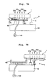
- the maintenance mechanism 9 includes a purge cap 40 provided to be movable vertically, to a base 42 which is positioned at a left side of the transporting route of the recording paper 7, and a wiper 41 which is provided to be movable vertically, to the base 42, and positioned at a right side of the purge cap 40.
- positions of the nozzle rows 25a to 25e of the ink-jet head 1 with respect to the scanning direction are shown by alternate long and short dash lines respectively.
- the purge cap 40 is capable of moving vertically, and can move to a purge position ( Fig. 7A ) which makes a contact with the ink jetting surface 1a and which covers the ejecting port 26 of the nozzle 20, and a purge preparation position ( Fig. 7B ) which does not make a contact with the ink jetting surface 1a.
- a suction pump 142 is connected to this purge cap 40.
- the purge cap 40 moves from the purge preparation position to the purge position, and makes a contact with the ink jetting surface 1a covering the ejecting port 26 of the nozzle 20 as shown in Fig. 7A .
- a space formed inside the purge cap 40 is vacuumed up by the suction pump 142, and the ink inside the nozzle 20 with the jetting defect is discharged forcibly to the space inside the purge cap 40.
- the wiper 41 is made of a flexible material such as a synthetic resin material or a rubber material.
- An upper end (front end) of the wiper is a free end, and a lower end is fixed to the base 42.
- the wiper 41 is capable of moving vertically, and the front end of the wiper 41 can be moved to a ready position ( Fig. 7A ) (at) which (the wiper 41) does not make a contact with the ink jetting surface 1a, and a wiping position ( Fig. 7B ) (at) which (the wiper 41) makes a contact with the ink jetting surface.
- a ready position Fig. 7A
- Fig. 7B at
- the wiper 41 when the ink-jet head 1 is moved to the stand-by position for performing the nozzle purge described above, the wiper 41 is at the ready position and does not make a contact with the ink jetting surface 1a of the ink-jet head 1 which moves. On the other hand, after the nozzle purge is over, the wiper 41 is moved from the ready position to the wiping position, and the front end of the wiper 41 makes a contact with the ink jetting surface 1a. In this state, as shown in Fig.
- the nozzle row 25a jetting the special color ink of the ink-jet head 1 is positioned at the extreme left end with respect to the scanning direction.
- the nozzle row 25a is positioned at the extreme downstream side with respect to the direction of movement. Therefore, as shown in Fig. 7B , an area of the ink jetting surface 1a, near the ejecting port 26 of the nozzle 20 jetting the special color ink is wiped at the last by the wiper 41. Consequently, the special color ink adhered to the ink jetting surface 1a is suppressed from being flowed into the nozzle 20 jetting other ink at the time of wiping.
- the black ink when the special color ink is not used, it is possible to make the black ink be jetted instead of the special color ink from the nozzle row 25a which basically jets the special color ink, according to a judgment of a user.
- the black ink since the black ink is jetted simultaneously from the two nozzle rows 25a and 25b which are shifted by P/2 in the paper feeding direction, the printing speed is increased than a printing speed in a case of performing a monochrome printing only by one nozzle row 25b.
- the ink cartridge 8a (refer to Fig. 1 ) of the special color ink is removed, and the special color ink in the ink reservoir 23a positioned at the extreme left of the reservoir unit 2, and the manifold 17a (refer to Fig. 2 ) of the channel unit 3 communicating with this ink reservoir 23a is discharged by sucking from an upstream side (opposite side of the nozzle 20), by a suction unit such as a pump.
- a cartridge for cleaning which supplies a cleaning liquid is connected to the tube 22, and the cleaning liquid is filled in the manifold 17a from the ink reservoir 23a of the reservoir unit 2.
- the special color ink remained in the ink reservoir 23a, the manifold 17a, and the individual ink channel 21 is discharged forcibly by the cleaning liquid, from nozzle 20 included in the nozzle row 25a.
- the ink cartridge 8b of the black ink is connected to the ink reservoir 23a of the reservoir unit 2 by the tube 22, and the black is filled into an ink channel from the ink reservoir 23a up to the nozzles 20 included in the nozzle row 25a.
- the black ink in the reservoir unit 2 and the channel unit 3 may be replaced by the special color ink in the same manner as described above.
- the user can determine and change the type of ink to be jetted from the nozzle row 25a (whether to jet the special color ink or the black ink).
- the ink which can be jetted from the nozzle row 25a may be determined at a manufacturing stage of the printer. In other words, whether the printer is to be a printer capable of jetting the special color ink from the nozzle row 25a, or a printer capable of a high-speed black and white printing (monochrome printer), jetting the black ink from both the nozzle rows 25a and 25b may be determined (at the manufacturing stage) .
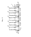
- the nozzle row 25a which is capable of jetting the special color ink is positioned adjacent to the nozzle row 25b which jets the black ink. Therefore, in a case of manufacturing a printer which is capable of the high-speed monochrome printing, it is possible to provide commonly a portion which supplies the black ink to each of the two nozzle rows 25a and 25b, and to simplify a structure of the printer. In other words, as shown in Fig. 8 , it is possible to supply the ink to each of the two nozzle rows 25a and 25b, from an ink cartridge 8f which stores the black ink.
- a reservoir unit 2A in the first modified embodiment includes four ink reservoirs 23f, 23c, 23d, and 23e arranged in a left and right direction.
- the ink reservoir 23f positioned at an extreme left side is connected to the ink cartridge 8f which stores the black ink, via the tube 22, and further communicates with the two manifolds 17a and 17b communicating with the nozzle rows 25a and 25b respectively, of the channel unit 3. Consequently, the black ink stored in the ink cartridge 8f is supplied to each of the nozzles 25a and 25b via the common ink reservoir 23f.
- the five nozzle rows 25a to 25e are positioned at the same interval with respect to the scanning direction (refer to Fig. 2 ).
- an interval between the nozzle row 25a jetting the special color ink and the nozzle row 25b jetting the black ink may be longer than an interval between the four nozzle rows 25b to 25e.
- the special color ink jetted from the nozzle row 25a is prevented assuredly from flowing into the nozzle 20 jetting the other ink.
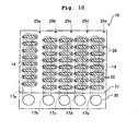
- the positions of nozzles 20 belonging to four nozzle rows which include the nozzle rows 25c to 25e for the color inks of three colors, and the nozzle row 25a for the special color ink with respect to the paper feeding direction may be aligned, and the nozzle row 25b for the black ink may be misaligned (shifted) by only P/2 in the paper feeding direction, with respect to the four nozzle rows 25a, and 25c to 25e.
- the black ink is made to be jetted also from the nozzle row 25a for the special color ink, the black ink is jetted simultaneously from the nozzle rows 25a and 25b shifted only by P/2 in the paper feeding direction. Therefore, the printing speed is increased than a speed in the case of performing the monochrome printing only by the nozzle row 25b.
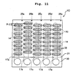
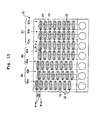
- an ink-jet head 1E shown in Fig. 13 includes a nozzle row group 60 (first nozzle row group) which includes the nozzles 20 jetting the black ink, a nozzle row group 61 (secondnozzle row group) which includes the nozzles 20 jetting color inks of three colors, and a nozzle row group 62 (third nozzle row group) which includes the nozzles 20 jetting the special color ink.
- each nozzle row group includes a plurality of nozzle rows including the same number of nozzles 20 arranged at pitch P (eight nozzles in Fig. 13 ) in the paper feeding direction.
- the nozzle row group 60 which jets the black ink includes two nozzle rows 60a and 60b (first nozzle sub array) which are mutually adjacent, and the nozzle row 60a on a left side is shifted with respect to the nozzle row 60b on a right side by P/2 toward a down stream side in the paper feeding direction.
- the nozzle row group 61 which jets the color ink includes nozzle rows 61a, 61b, and 61c (second nozzle sub array) jetting color inks of three types respectively, and in these three nozzle rows 61a to 61c, positions of the nozzles 20 in the paper feeding direction, included in each nozzle row coincide mutually, and further, are the same positions as the nozzle 20 included in the nozzle row 60b on the right side for the black ink.
- the nozzle row group 60 which jets the black ink and the nozzle row group 62 which jets the special color ink since the interval between the nozzles (pitch) in the scanning direction is P/2, the printing speed at the time of performing the printing by the black ink and the special color ink is increased.
- the pitch of the nozzles 20 jetting the black ink becomes P/4. Consequently, the printing speed in the monochrome printing in increased.
- the nozzle row group 62 which jets the special color ink is positioned at the extreme left end in the scanning direction.
- the nozzle row group 62 is positioned at an extreme downstream side in a direction of relative movement of the wiper 41 (refer to Fig. 7 ), with respect to the ink jetting surface. Therefore, an area around the ejecting ports 26 of the nozzles 20 included in the nozzle row group 62 which jet the special color ink is wiped at the last by the wiper 41. Consequently, even in this ink-jet head IE, at the time of wiping, the special color ink adhered to the ink jetting surface during a nozzle purge is suppressed from flowing into the nozzle 20 which jets the other ink.
- a direction of arrangement (first direction) of the nozzles 20 is orthogonal to the paper feeding direction (second direction) which is a direction in which the nozzle rows are arranged (refer to Fig. 3 ).
- the direction of arrangement of the nozzles 20 may intersect the scanning direction at an angle other than 90°, and an effect substantially similar to an effect in the embodiment is achieved provided that at least these two directions are not parallel mutually.
- the ink-jet head in the embodiment described above is an ink-jet head of serial type which jets ink on to a recording paper while moving in a direction of width of the recording paper.
- the present invention is also applicable to an ink-jet head of line type, which includes a plurality of nozzle rows extended across the entire width of the recording paper.
- the present invention is not restricted to the ink-jet head which records an image etc. on the recording paper, and is also applicable to an ink-jet head which records (an image etc.) on various recordingmedia suchas a cloth, a textile fabric, and a metal plate.
Landscapes
- Ink Jet (AREA)
- Particle Formation And Scattering Control In Inkjet Printers (AREA)
Claims (7)
- Tête à jet d'encre projetant une encre, comprenant :une première rangée de buses (60) comprenant une pluralité de premières buses disposées dans une première direction et projetant une encre noire ;une seconde rangée de buses (61) comprenant une pluralité de secondes buses disposées dans la première direction et projetant une encre de couleur contribuant à une impression en couleurs ; etune troisième rangée de buses (62) comprenant une pluralité de troisièmes buses disposées dans la première direction et projetant une encre de couleur spéciale qui est une encre différente de l'encre noire et de l'encre de couleur,dans lequel la première rangée de buses (60), la seconde rangée de buses (61) et la troisième rangée de buses (62) sont disposées dans une seconde direction croisant la première direction, et la troisième rangée de buses (62) est disposée à une extrémité par rapport à la seconde direction,caractérisée en ce que :la première rangée de buses (60) comprend deux premiers sous-ensembles de buses (60a, 60b) comprenant chacun un nombre prédéterminé de premières buses disposées dans la première direction au pas P, et les deux premiers sous-ensembles de buses (60a, 60b) sont positionnés pour être déplacés mutuellement par P/2, dans la première direction ;la seconde rangée de buses (61) comprend une pluralité de seconds sous-ensembles de buses (61a, 61b, 61c) comprenant chacun le nombre prédéterminé de secondes buses disposées dans la première direction au pas P, les secondes buses appartenant à chacun des seconds sous-ensembles de buses (61a, 61b, 61c) sont positionnées dans une même position par rapport à la première direction, et l'encre de couleur comprend une pluralité d'encres de couleurs secondaires de couleur mutuellement différente et chacune étant projetée depuis les secondes buses appartenant à l'un des seconds sous-ensembles de buses (61a, 61b, 61c) ;la troisième rangée de buses (62) comprend deux troisièmes sous-ensembles de buses (62a, 62b) comprenant un nombre prédéterminé de troisièmes buses disposées dans la première direction au pas P, et les deux troisièmes sous-ensembles de buses (62a, 62b) sont positionnés pour être déplacés mutuellement par P/2, dans la première direction, et les deux troisièmes sous-ensembles de buses (62a, 62b) sont positionnés pour être déplacés seulement par P/4 dans la première direction, par rapport au premier sous-ensemble de buses (60a, 60b).
- Tête à jet d'encre selon la revendication 1, dans laquelle la troisième rangée de buses (62) est positionnée à côté de la première rangée de buses (60).
- Tête à jet d'encre selon la revendication 1, dans laquelle la première direction est orthogonale à la seconde direction.
- Tête à jet d'encre selon l'une quelconque des revendications 1 à 3, dans laquelle l'encre de couleur spéciale est une encre sélectionnée parmi un groupe composé d'une encre d'or, une encre d'argent, une encre blanche, une encre transparente, une encre aromatique, une encre fluorescente, une encre fluorescente ultraviolette, et une encre magnétique.
- Imprimante à jet d'encre comprenant la tête à jet d'encre selon la revendication 1.
- Imprimante à jet d'encre selon la revendication 5, dans laquelle :la tête à jet d'encre (1E) comprend une surface de projection d'encre (1a) dans laquelle les orifices d'éjection (26) des premières buses, des secondes buses, et des troisièmes buses sont formés ; l'imprimante à jet d'encre (100) comprend également un essuyeur (41) mobile par rapport à la surface de projection d'encre (1a) dans la seconde direction, et essuie l'encre collée à la surface de projection d'encre (1a) ; et la troisième rangée de buses (25a) est positionnée à un côté aval le plus éloigné par rapport à une direction dans laquelle l'essuyeur (41) se déplace tout en essuyant la surface de projection d'encre.
- Imprimante à jet d'encre selon la revendication 5, comprenant également un mécanisme d'entretien (9) entretenant la tête à jet d'encre (1E), le mécanisme d'entretien (9) comprenant un capuchon (40) couvrant la tête à jet d'encre (1E), un mécanisme d'aspiration (142) aspirant l'encre à travers le capuchon (40), et un essuyeur (41) ayant de la flexibilité.
Applications Claiming Priority (1)
| Application Number | Priority Date | Filing Date | Title |
|---|---|---|---|
| JP2005286229A JP2007090805A (ja) | 2005-09-30 | 2005-09-30 | インクジェットヘッド及びインクジェットプリンタ |
Publications (2)
| Publication Number | Publication Date |
|---|---|
| EP1769926A1 EP1769926A1 (fr) | 2007-04-04 |
| EP1769926B1 true EP1769926B1 (fr) | 2009-09-30 |
Family
ID=37636642
Family Applications (1)
| Application Number | Title | Priority Date | Filing Date |
|---|---|---|---|
| EP06020313A Not-in-force EP1769926B1 (fr) | 2005-09-30 | 2006-09-27 | Tête et imprimante à jet d'encre |
Country Status (4)
| Country | Link |
|---|---|
| US (1) | US7503640B2 (fr) |
| EP (1) | EP1769926B1 (fr) |
| JP (1) | JP2007090805A (fr) |
| DE (1) | DE602006009451D1 (fr) |
Families Citing this family (16)
| Publication number | Priority date | Publication date | Assignee | Title |
|---|---|---|---|---|
| KR100649445B1 (ko) * | 2005-10-17 | 2006-11-27 | 삼성전기주식회사 | 배선형성 방법 및 장치 |
| JP5401968B2 (ja) * | 2008-12-17 | 2014-01-29 | セイコーエプソン株式会社 | 液滴吐出ヘッドの液状体撹拌方法及び液滴吐出装置 |
| JP5104745B2 (ja) * | 2008-12-22 | 2012-12-19 | ブラザー工業株式会社 | インクジェットヘッド |
| US8356874B2 (en) * | 2009-04-08 | 2013-01-22 | Redwood Technologies, Llc | Apparatus and method for precision application and metering of a two-part (binary) imaging solution in an ink jet printer |
| US8960880B2 (en) | 2009-04-08 | 2015-02-24 | Redwood Technologies, Llc | Binary epoxy ink and enhanced printer systems, structures, and associated methods |
| US8887393B2 (en) * | 2012-01-27 | 2014-11-18 | Eastman Kodak Company | Fabrication of an inkjet printhead mounting substrate |
| JP5832360B2 (ja) * | 2012-04-04 | 2015-12-16 | 富士フイルム株式会社 | インクジェット記録装置 |
| US8939536B2 (en) * | 2012-05-02 | 2015-01-27 | Xerox Corporation | Method and system for aligning printheads that eject clear ink in an inkjet printer |
| US9815285B2 (en) * | 2015-12-03 | 2017-11-14 | Ricoh Company, Ltd. | Liquid discharge head, liquid discharge device, and liquid discharge apparatus |
| JP6851736B2 (ja) * | 2016-07-13 | 2021-03-31 | キヤノン株式会社 | 液体吐出ヘッドおよび液体吐出装置 |
| US10279585B2 (en) | 2017-01-31 | 2019-05-07 | Xerox Corporation | Method and system for aligning ejectors that eject clear materials in a printer |
| US11198311B2 (en) | 2019-03-28 | 2021-12-14 | Brother Kogyo Kabushiki Kaisha | Liquid ejection device |
| JP7183911B2 (ja) * | 2019-03-28 | 2022-12-06 | ブラザー工業株式会社 | インクジェットプリンタ |
| JP7484195B2 (ja) * | 2020-01-31 | 2024-05-16 | セイコーエプソン株式会社 | 液体噴射ヘッド及び液体噴射装置 |
| KR102565342B1 (ko) * | 2021-06-03 | 2023-08-08 | 조선영 | 잉크젯 프린트 헤드용 세척 수리 장치 |
| CN115262120A (zh) * | 2022-09-05 | 2022-11-01 | 陈曼勒 | 一种具有自动调整功能的涂布机 |
Family Cites Families (27)
| Publication number | Priority date | Publication date | Assignee | Title |
|---|---|---|---|---|
| DE69232977T2 (de) * | 1991-07-30 | 2003-11-06 | Canon K.K., Tokio/Tokyo | Vorrichtung und Verfahren zum Tintenstrahlaufzeichnen |
| JP3140243B2 (ja) | 1993-03-01 | 2001-03-05 | キヤノン株式会社 | インクジェット記録装置 |
| CA2110447C (fr) | 1992-12-03 | 2001-08-07 | Kazuyoshi Takahashi | Appareil et methode de production d'images, methode d'impression a jet d'encre et imprime obtenu avec cette methode |
| JP3376027B2 (ja) | 1992-12-04 | 2003-02-10 | キヤノン株式会社 | 布帛用画像形成装置、布帛用画像形成方法および画像形成がなされた布帛からなる物品、並びにプリント物の製造方法 |
| JP3347541B2 (ja) * | 1994-08-10 | 2002-11-20 | キヤノン株式会社 | インクジェット記録方法、インクジェット記録装置、記録ヘッド、情報処理システム、および記録物 |
| JP3337879B2 (ja) * | 1995-02-13 | 2002-10-28 | キヤノン株式会社 | インクジェットプリント方法およびこれに用いられるインクジェットヘッド、インクジェットカートリッジおよびインクジェットプリント装置 |
| JP3472027B2 (ja) * | 1996-03-26 | 2003-12-02 | キヤノン株式会社 | インクジェットプリント方法 |
| JPH10128963A (ja) | 1996-10-31 | 1998-05-19 | Seiko Epson Corp | インクジェット記録装置並びにその使用法 |
| JPH11138864A (ja) * | 1997-11-12 | 1999-05-25 | Ricoh Co Ltd | インクジェット記録装置及びプリンタドライバ |
| JP3603311B2 (ja) * | 1998-07-27 | 2004-12-22 | セイコーエプソン株式会社 | 二液を用いたインクジェット記録方法 |
| US6312121B1 (en) | 1998-09-11 | 2001-11-06 | Xerox Corporation | Ink jet printing process |
| JP2002011872A (ja) | 1999-05-06 | 2002-01-15 | Seiko Epson Corp | 液体噴射装置、画像記録装置、及び液体噴射装置の駆動方法、並びにコンピュータ読み取り可能な記録媒体 |
| US6827423B1 (en) | 1999-05-06 | 2004-12-07 | Seiko Epson Corporation | Liquid jetting apparatus, method of driving the same, computer-readable recording medium storing the method and image recording apparatus incorporating the same |
| US6502920B1 (en) * | 2000-02-04 | 2003-01-07 | Lexmark International, Inc | Ink jet print head having offset nozzle arrays |
| US6902252B1 (en) * | 2000-08-16 | 2005-06-07 | Hewlett-Packard Development Company, L.P. | Fluid ejection device with staggered ink drop generators |
| US6435658B1 (en) * | 2000-09-04 | 2002-08-20 | Canon Kabushiki Kaisha | Ink jet recording method |
| JP2002292849A (ja) | 2001-03-28 | 2002-10-09 | Seiko Epson Corp | インクジェット記録装置 |
| JP4244532B2 (ja) * | 2001-05-15 | 2009-03-25 | セイコーエプソン株式会社 | カートリッジの選択により特徴を変更できる印刷 |
| US6655797B2 (en) * | 2002-04-30 | 2003-12-02 | Hewlett-Packard Development Company, L.P. | Deposition of fixer and overcoat by an inkjet printing system |
| US6896348B2 (en) * | 2002-07-23 | 2005-05-24 | Canon Kabushiki Kaisha | Ink jet printing apparatus, ink jet printing method, program, and printing medium |
| JP3750808B2 (ja) * | 2002-07-26 | 2006-03-01 | ブラザー工業株式会社 | インクジェットプリンタ |
| JP4581462B2 (ja) * | 2003-04-10 | 2010-11-17 | セイコーエプソン株式会社 | 印刷装置、印刷ヘッド、及び、印刷方法 |
| JP4561103B2 (ja) * | 2004-01-16 | 2010-10-13 | コニカミノルタエムジー株式会社 | インクジェット記録装置 |
| JP4307319B2 (ja) * | 2004-04-30 | 2009-08-05 | キヤノン株式会社 | 記録装置及び記録方法 |
| JP3925525B2 (ja) * | 2004-10-01 | 2007-06-06 | セイコーエプソン株式会社 | 液滴吐出装置、パネルの製造方法、画像表示装置および電子機器 |
| US7350902B2 (en) * | 2004-11-18 | 2008-04-01 | Eastman Kodak Company | Fluid ejection device nozzle array configuration |
| EP1881898B1 (fr) * | 2005-05-17 | 2019-12-25 | Ricoh Company, Ltd. | Appareil d'imagerie |
-
2005
- 2005-09-30 JP JP2005286229A patent/JP2007090805A/ja active Pending
-
2006
- 2006-09-27 DE DE602006009451T patent/DE602006009451D1/de active Active
- 2006-09-27 EP EP06020313A patent/EP1769926B1/fr not_active Not-in-force
- 2006-09-28 US US11/536,154 patent/US7503640B2/en active Active
Also Published As
| Publication number | Publication date |
|---|---|
| EP1769926A1 (fr) | 2007-04-04 |
| DE602006009451D1 (de) | 2009-11-12 |
| JP2007090805A (ja) | 2007-04-12 |
| US7503640B2 (en) | 2009-03-17 |
| US20070076050A1 (en) | 2007-04-05 |
Similar Documents
| Publication | Publication Date | Title |
|---|---|---|
| US8210674B2 (en) | Liquid droplet jetting apparatus | |
| US7503640B2 (en) | Ink-jet head and ink-jet printer | |
| US8231208B2 (en) | Liquid ejection head | |
| CN102036822B (zh) | 喷射流体的装置和方法 | |
| CN101797842B (zh) | 喷墨打印头 | |
| JP5598116B2 (ja) | 液滴噴射装置 | |
| JP2011213030A (ja) | 液体噴射ヘッド、液体噴射ユニット及び液体噴射装置 | |
| JP4872894B2 (ja) | 液滴噴射装置 | |
| US7401905B2 (en) | Ink-jet head with ink blockage prevention device | |
| JP2011018836A (ja) | 圧電型アクチュエータの製造方法、及び該製造方法によって製造された圧電型アクチュエータ | |
| US7537307B2 (en) | Liquid-droplet jetting apparatus | |
| JP2008080797A (ja) | 液滴吐出ヘッド及びこれを備えた液滴吐出装置 | |
| US7306328B2 (en) | Ink jet printer head | |
| JP4792848B2 (ja) | インクジェット記録装置 | |
| JP2007008157A (ja) | 液滴噴射装置 | |
| JP5728934B2 (ja) | ヘッド回復装置及び画像形成装置 | |
| JP2012131148A (ja) | 液体噴射ヘッド、液体噴射ユニット及び液体噴射装置 | |
| JP3909746B2 (ja) | 液滴吐出ヘッド及びインクジェット記録装置 | |
| JP2016185606A (ja) | 液体吐出ヘッド、および、液体吐出装置 | |
| JP2015058583A (ja) | 液滴吐出ヘッド及び画像形成装置 | |
| US20170072721A1 (en) | Ink jet printer | |
| JP2003326719A (ja) | インクジェット記録ヘッドおよびインクジェット記録装置 | |
| JP3690186B2 (ja) | インクジェット式記録ヘッド | |
| JP4760405B2 (ja) | 液滴噴射装置 | |
| CN118871297A (zh) | 液体喷出头以及记录装置 |
Legal Events
| Date | Code | Title | Description |
|---|---|---|---|
| PUAI | Public reference made under article 153(3) epc to a published international application that has entered the european phase |
Free format text: ORIGINAL CODE: 0009012 |
|
| AK | Designated contracting states |
Kind code of ref document: A1 Designated state(s): AT BE BG CH CY CZ DE DK EE ES FI FR GB GR HU IE IS IT LI LT LU LV MC NL PL PT RO SE SI SK TR |
|
| AX | Request for extension of the european patent |
Extension state: AL BA HR MK YU |
|
| 17P | Request for examination filed |
Effective date: 20071004 |
|
| 17Q | First examination report despatched |
Effective date: 20071102 |
|
| AKX | Designation fees paid |
Designated state(s): DE FR GB |
|
| GRAP | Despatch of communication of intention to grant a patent |
Free format text: ORIGINAL CODE: EPIDOSNIGR1 |
|
| GRAS | Grant fee paid |
Free format text: ORIGINAL CODE: EPIDOSNIGR3 |
|
| GRAA | (expected) grant |
Free format text: ORIGINAL CODE: 0009210 |
|
| AK | Designated contracting states |
Kind code of ref document: B1 Designated state(s): DE FR GB |
|
| REG | Reference to a national code |
Ref country code: GB Ref legal event code: FG4D |
|
| REF | Corresponds to: |
Ref document number: 602006009451 Country of ref document: DE Date of ref document: 20091112 Kind code of ref document: P |
|
| PLBE | No opposition filed within time limit |
Free format text: ORIGINAL CODE: 0009261 |
|
| STAA | Information on the status of an ep patent application or granted ep patent |
Free format text: STATUS: NO OPPOSITION FILED WITHIN TIME LIMIT |
|
| 26N | No opposition filed |
Effective date: 20100701 |
|
| REG | Reference to a national code |
Ref country code: FR Ref legal event code: PLFP Year of fee payment: 11 |
|
| REG | Reference to a national code |
Ref country code: FR Ref legal event code: PLFP Year of fee payment: 12 |
|
| REG | Reference to a national code |
Ref country code: FR Ref legal event code: PLFP Year of fee payment: 13 |
|
| PGFP | Annual fee paid to national office [announced via postgrant information from national office to epo] |
Ref country code: FR Payment date: 20190819 Year of fee payment: 14 |
|
| PGFP | Annual fee paid to national office [announced via postgrant information from national office to epo] |
Ref country code: GB Payment date: 20190827 Year of fee payment: 14 |
|
| GBPC | Gb: european patent ceased through non-payment of renewal fee |
Effective date: 20200927 |
|
| PG25 | Lapsed in a contracting state [announced via postgrant information from national office to epo] |
Ref country code: FR Free format text: LAPSE BECAUSE OF NON-PAYMENT OF DUE FEES Effective date: 20200930 |
|
| PG25 | Lapsed in a contracting state [announced via postgrant information from national office to epo] |
Ref country code: GB Free format text: LAPSE BECAUSE OF NON-PAYMENT OF DUE FEES Effective date: 20200927 |
|
| PGFP | Annual fee paid to national office [announced via postgrant information from national office to epo] |
Ref country code: DE Payment date: 20230808 Year of fee payment: 18 |
|
| REG | Reference to a national code |
Ref country code: DE Ref legal event code: R119 Ref document number: 602006009451 Country of ref document: DE |
|
| PG25 | Lapsed in a contracting state [announced via postgrant information from national office to epo] |
Ref country code: DE Free format text: LAPSE BECAUSE OF NON-PAYMENT OF DUE FEES Effective date: 20250401 |