EP1770031B1 - Moyen de convoyage de feuilles d'une machine travaillant ces feuilles, plus particulièrement des feuilles de verre ou matériau similaire - Google Patents
Moyen de convoyage de feuilles d'une machine travaillant ces feuilles, plus particulièrement des feuilles de verre ou matériau similaire Download PDFInfo
- Publication number
- EP1770031B1 EP1770031B1 EP20060020102 EP06020102A EP1770031B1 EP 1770031 B1 EP1770031 B1 EP 1770031B1 EP 20060020102 EP20060020102 EP 20060020102 EP 06020102 A EP06020102 A EP 06020102A EP 1770031 B1 EP1770031 B1 EP 1770031B1
- Authority
- EP
- European Patent Office
- Prior art keywords
- sheet
- belts
- sheets
- assembly
- belt
- Prior art date
- Legal status (The legal status is an assumption and is not a legal conclusion. Google has not performed a legal analysis and makes no representation as to the accuracy of the status listed.)
- Not-in-force
Links
Images




Classifications
-
- B—PERFORMING OPERATIONS; TRANSPORTING
- B65—CONVEYING; PACKING; STORING; HANDLING THIN OR FILAMENTARY MATERIAL
- B65G—TRANSPORT OR STORAGE DEVICES, e.g. CONVEYORS FOR LOADING OR TIPPING, SHOP CONVEYOR SYSTEMS OR PNEUMATIC TUBE CONVEYORS
- B65G49/00—Conveying systems characterised by their application for specified purposes not otherwise provided for
- B65G49/05—Conveying systems characterised by their application for specified purposes not otherwise provided for for fragile or damageable materials or articles
- B65G49/06—Conveying systems characterised by their application for specified purposes not otherwise provided for for fragile or damageable materials or articles for fragile sheets, e.g. glass
- B65G49/063—Transporting devices for sheet glass
- B65G49/064—Transporting devices for sheet glass in a horizontal position
-
- C—CHEMISTRY; METALLURGY
- C03—GLASS; MINERAL OR SLAG WOOL
- C03B—MANUFACTURE, SHAPING, OR SUPPLEMENTARY PROCESSES
- C03B33/00—Severing cooled glass
- C03B33/02—Cutting or splitting sheet glass or ribbons; Apparatus or machines therefor
- C03B33/023—Cutting or splitting sheet glass or ribbons; Apparatus or machines therefor the sheet or ribbon being in a horizontal position
- C03B33/03—Glass cutting tables; Apparatus for transporting or handling sheet glass during the cutting or breaking operations
-
- Y—GENERAL TAGGING OF NEW TECHNOLOGICAL DEVELOPMENTS; GENERAL TAGGING OF CROSS-SECTIONAL TECHNOLOGIES SPANNING OVER SEVERAL SECTIONS OF THE IPC; TECHNICAL SUBJECTS COVERED BY FORMER USPC CROSS-REFERENCE ART COLLECTIONS [XRACs] AND DIGESTS
- Y10—TECHNICAL SUBJECTS COVERED BY FORMER USPC
- Y10T—TECHNICAL SUBJECTS COVERED BY FORMER US CLASSIFICATION
- Y10T83/00—Cutting
- Y10T83/444—Tool engages work during dwell of intermittent workfeed
- Y10T83/4604—Work feed functions as tool support
-
- Y—GENERAL TAGGING OF NEW TECHNOLOGICAL DEVELOPMENTS; GENERAL TAGGING OF CROSS-SECTIONAL TECHNOLOGIES SPANNING OVER SEVERAL SECTIONS OF THE IPC; TECHNICAL SUBJECTS COVERED BY FORMER USPC CROSS-REFERENCE ART COLLECTIONS [XRACs] AND DIGESTS
- Y10—TECHNICAL SUBJECTS COVERED BY FORMER USPC
- Y10T—TECHNICAL SUBJECTS COVERED BY FORMER US CLASSIFICATION
- Y10T83/00—Cutting
- Y10T83/444—Tool engages work during dwell of intermittent workfeed
- Y10T83/461—With abutment to position work being fed with respect to cutter
-
- Y—GENERAL TAGGING OF NEW TECHNOLOGICAL DEVELOPMENTS; GENERAL TAGGING OF CROSS-SECTIONAL TECHNOLOGIES SPANNING OVER SEVERAL SECTIONS OF THE IPC; TECHNICAL SUBJECTS COVERED BY FORMER USPC CROSS-REFERENCE ART COLLECTIONS [XRACs] AND DIGESTS
- Y10—TECHNICAL SUBJECTS COVERED BY FORMER USPC
- Y10T—TECHNICAL SUBJECTS COVERED BY FORMER US CLASSIFICATION
- Y10T83/00—Cutting
- Y10T83/444—Tool engages work during dwell of intermittent workfeed
- Y10T83/463—Work-feed element contacts and moves with work
-
- Y—GENERAL TAGGING OF NEW TECHNOLOGICAL DEVELOPMENTS; GENERAL TAGGING OF CROSS-SECTIONAL TECHNOLOGIES SPANNING OVER SEVERAL SECTIONS OF THE IPC; TECHNICAL SUBJECTS COVERED BY FORMER USPC CROSS-REFERENCE ART COLLECTIONS [XRACs] AND DIGESTS
- Y10—TECHNICAL SUBJECTS COVERED BY FORMER USPC
- Y10T—TECHNICAL SUBJECTS COVERED BY FORMER US CLASSIFICATION
- Y10T83/00—Cutting
- Y10T83/444—Tool engages work during dwell of intermittent workfeed
- Y10T83/4637—With means to guide, position, or present work to work-feed means
- Y10T83/464—Means to transport work to work-feed means
Definitions
- the present invention relates to an assembly for conveying sheets on machines for working sheets, particularly glass sheets and the like.
- the conveyance assembly is provided with presser rollers or belts, which engage the surface of the sheet and retain it during work; these means very often cause damage to the surface of the sheet, especially when working on glass sheets with a "LOW-E" type coating.
- One of such sides is typically fixed, while the other pair of belts can perform a translational motion so as to adapt easily to the width of the sheet.
- Each pair of belts is formed by a belt which is fixed on the supporting surface and engages the lower side of the sheet, while the other belt can move vertically in order to engage the upper side so as to apply an adequate pressure which ensures the retention of the sheet during work.
- Another problem consists further in that it is not always possible to retain the sheet firmly, and therefore work imperfections and vibrations can occur which damage the tools and produce lower-quality work.
- JP-2004026569 discloses an apparatus for performing scribing, breaking or chamfering of a glass plate by repeating a sending action of the glass plate and a working action for fixing the glass plate and working the glass plate in the sending direction or the direction orthogonally crossing the sending direction.
- US-2004/0237737 discloses a process and device for moving and positioning sheets of glass.
- the aim of the invention is to solve the problems described above by providing an assembly for conveying sheets on machines for working sheets, particularly glass sheets and the like, which allows to work both along the edges of the sheet and on the surface of the sheet, with the additional possibility to move the working heads so that they work in both directions of advancement of the sheet.
- an object of the invention is to provide a conveyance assembly which does not produce surface damage of the sheets, which are always retained perfectly, so that all work can be performed in an optimum manner.
- Another object of the present invention is to provide a conveyance assembly which, thanks to its particular constructive characteristics, is capable of giving the greatest assurances of reliability and safety in use.
- Still another object of the present invention is to provide an assembly for conveying sheets on machines for working sheets, particularly glass sheets and the like, which can be obtained easily starting from commonly commercially available elements and materials and is further competitive from a merely economical standpoint.
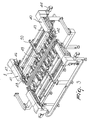
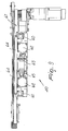
- the assembly for conveying sheets on machines for working sheets, particularly glass sheets, generally designated by the reference numeral 1 comprises a sheet feeder assembly 2 and a sheet removal assembly 3, which are arranged respectively upstream and downstream of a working machine 4 which is interposed between the two removal assemblies.
- a sheet insertion assembly designated by the reference numeral 6, which is provided by means of a conventional roller bed, and an output assembly, constituted by a roller bed 7 arranged at the output of the removal assembly.
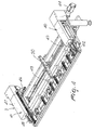
- a particular feature of the invention consists in that the sheet feeder assembly that engages the longitudinal edges of the sheets, where "longitudinal” refers to the direction of advancement of the sheets, is constitute by means of a supporting frame 10, which supports the elements that constitute the assembly, which is constituted by a pair of mutually opposite fixed-position belts 11, and a pair of mutually opposite variable-position belts 12, which can perform a translational motion toward and away from the pair of fixed-position belts in order to adapt to the width of the sheet.
- the pairs of belts 11 and 12 are constituted respectively by a lower fixed-position feeder belt 13, which is actuated by a first motor 14, which moves the belt.
- a controlled feeder belt 15 with adjustable position is positioned above the belt 13 and can perform a translational motion along a direction which is perpendicular to the plane of arrangement of the sheet, designated by the reference letter L, so as to adapt to the thickness of the sheet.
- the belt 15 is actuated with positioning means which will be described hereinafter.
- variable-position belts 12 are provided with a lower, fixed-position, feeder belt 20, which lies below the sheet and is connected to and actuated by a second motor 21.
- An adjustable upper feeder belt 22 is arranged above the belt 20, which can perform a translational motion on a direction perpendicular to the sheet arrangement plane, and can also be motorized or free.
- the feeder assembly is completed by a transverse feeder roller 30, which engages the lower face of the sheet and in practice supports it along a transverse direction, i.e., at right angles to the extension of the longitudinal edges.
- central rollers 32 which are designed to support large sheets and are arranged halfway along the width of the sheet.
- the removal assembly 3 is constituted by a pair of fixed-position removal belts 40, opposite to which there is a pair of variable-position removal belts 41, which like the pair of belts 12 can perform a translational motion in order to adapt to the different widths of the sheet.
- the pairs of belts 40 and 41 in a manner similar to the pairs 11 and 12, are provided by means of a lower fixed-position removal belt 42, above which there is an adjustable upper removal belt 43.
- the belt 42 is connected to a third motor 44, while the belt 43 in this case also can be motorized or free.
- the pair of belts 41 is provided with a lower variable or movable-position belt 46, which is connected to a fourth motor 47, above which an adjustable removal belt 48 is arranged that can perform a translational motion along a direction perpendicular to the sheet arrangement plane.
- the assembly is completed by a transverse roller 49, which engages along the transverse direction of the sheet, and a removal assembly formed of a series of central removal rollers 50, which support large sheets.
- Each pair of belts 11, 12, 40 and 41 is arranged at rollers abutment 55 which have a vertical axis and are designed to act as an abutment and positioning element by engaging the edge of the sheet.
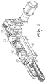
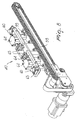
- each pair of belts has a parallelogram mechanism 60, which supports the entire belt positioning means 61, on which a vertical actuation cylinder 62 is connected which makes the upper belts 15, 22, 43, 48 press against the upper surface of the glass sheet at the set pressure.
- a block 63 is actuated and acts on the stem of a cylinder 62, such block 63 constituting belt locking means for locking in position the adjustable belts.
- the upper belts have a covering provided by surface treatment which prevents damage of the surface layers sometimes provided on the upper face of the glass sheet.
- the working machine 4 is interposed advantageously between the feeder assembly and the removal assembly and supports one or more working heads; designated by the reference numeral 70, which can move along the transverse direction and can perform a translational motion at right angles to the plane of arrangement of the sheet.
- the sheet is always retained perfectly in close proximity to the work area, thanks to the fact that the belts always engage the longitudinal edges of the sheet and there is also a roller which is positioned on the transverse edge and retains the sheet.
- the sheet L to be worked is guided by means of the roller bed 6 which is located upstream of the feeder assembly and the sheet is already positioned with its longitudinal edges parallel to the advancement line and with its transverse edges at right angles.
- One of the longitudinal edges is already positioned on the reference constituted by the rollers having a vertical axis.
- the pairs of variable-positioning belts are positioned as a function of the size of the sheet, which is set by a numeric control, and when the sheet engages the pairs of belts along their length the movable pairs perform an additional stroke, which allows to generate a lateral pressure between the sheet L and the rollers 55 having a vertical axis, in order to ensure correct alignment of the sheet against the references.
- the upper belts descend at the preset pressure, until the closure position is reached, as indicated by a pressure switch; the block 63 is activated and locks the upper structure, which can move at right angles to the plane of arrangement of the sheet.
- the upper belts of the removal assembly descend at the preset pressure, and when the closure position indicated by a pressure switch is reached, the locking systems are activated as in the preceding case.
- the invention achieves the proposed aim and objects, and in particular the fact is stressed that the use of two separate conveyance assemblies, i.e., the feeder assembly and the removal assembly, allows to work on any point of the sheet, since the working heads are in practice independent of the structure that provides the movement of the sheet and can move transversely and vertically.
- the removal assembly moves away the sheet on the downstream roller bed.
- the feeder and removal assemblies can move synchronously, typically during working, or at different speeds in order to move away a finished part and simultaneously set up a new part in input.
- the pneumatic movement system for the upper belts avoids the need to check their position as a function of the thickness of the glass sheet.
Landscapes
- Chemical & Material Sciences (AREA)
- Engineering & Computer Science (AREA)
- Materials Engineering (AREA)
- Organic Chemistry (AREA)
- Registering Or Overturning Sheets (AREA)
- Re-Forming, After-Treatment, Cutting And Transporting Of Glass Products (AREA)
- Automobile Manufacture Line, Endless Track Vehicle, Trailer (AREA)
- Glass Compositions (AREA)
- Sheets, Magazines, And Separation Thereof (AREA)
Claims (13)
- Ensemble pour transporter des feuilles sur des machines (4) de traitement de feuilles, en particulier des feuilles de verre et analogues, comprenant un ensemble (2) pour acheminer les feuilles à traiter, qui s'engage sur les bords longitudinaux des feuilles et est agencé en amont d'un châssis (4a) pour supporter au moins une tête de traitement (70), et un ensemble (3) pour retirer les feuilles, qui s'engage sur les bords longitudinaux des feuilles et est agencé en aval dudit châssis (4a) pour supporter une tête de traitement (70), caractérisé en ce que ledit ensemble d'acheminement des feuilles (2) et ledit ensemble de retrait des feuilles (3) sont :- chacun munis d'une paire de courroies à position fixe mutuellement opposées (11, 40) et d'une paire de courroies à position variable mutuellement opposées (12, 41),- lesdites courroies à position variable (12, 41) ayant une position variable afin de s'adapter à la largeur de la feuille,- lesdites paires de courroies étant prévues pour chaque bord longitudinal de la feuille (L) et étant constituées d'une courroie fixe inférieure (13, 20, 42, 46) et d'une courroie supérieure (15, 22, 43, 48), ladite courroie supérieure ayant une position variable afin de s'adapter à la largeur de la feuille.
- Ensemble de transport selon la revendication 1, caractérisé en ce que ladite paire de courroies à position fixe (11) ont une courroie d'alimentation inférieure à position fixe (13) actionnée par un premier moteur (14), une courroie (15) dont la position peut être ajustée dans une direction perpendiculaire au plan d'agencement de ladite feuille (L) qui est positionnée au-dessus de ladite courroie d'alimentation inférieure à position fixe (13).
- Ensemble de transport selon la revendication 1, caractérisé en ce que ladite paire de courroies d'alimentation à position variable (12) est munie d'une courroie d'alimentation inférieure à position fixe (20), qui est actionnée par un deuxième moteur (21) et au-dessus de laquelle se trouve une courroie à position ajustable (22), qui peut effectuer un mouvement de translation dans une direction perpendiculaire au plan d'agencement de la feuille (L).
- Ensemble de transport selon la revendication 1, caractérisé en ce que ladite paire de courroies de retrait à position fixe (40) comprend une courroie de retrait inférieure à position fixe (42), au-dessus de laquelle se trouve une courroie de retrait ajustable (43), qui peut effectuer un mouvement de translation dans une direction à angles droits avec le plan d'agencement de la feuille (L).
- Ensemble de transport selon la revendication 1, caractérisé en ce que ladite paire de courroies de retrait à position variable (41) comprend une courroie de retrait inférieure à position mobile (46), qui est actionnée par un quatrième moteur (47) au-dessus duquel se trouve une courroie de retrait ajustable (48), qui peut effectuer un mouvement de translation dans une direction perpendiculaire au plan d'agencement de la feuille (L).
- Ensemble de transport selon une ou plusieurs des revendications précédentes, caractérisé en ce qu'il comprend, pour ledit ensemble d'acheminement (2) et pour ledit ensemble de retrait (3), un galet transversal (49) qui s'engage sur la face inférieure de la feuille (L) dans une direction transversale à angles droits par rapport à ladite direction longitudinale.
- Ensemble de transport selon une ou plusieurs des revendications précédentes, caractérisé en ce qu'il comprend, pour ledit ensemble d'acheminement (2) et pour ledit ensemble de retrait (3), une série de galets centraux (50), qui peuvent être positionnés dans une partie centrale de la largeur de la feuille (L) en cours de traitement.
- Ensemble de transport selon la revendication 1, caractérisé en ce que des galets (55) ayant un axe vertical sont positionnés sur chaque paire de courroies et sont à même d'agir comme un élément de butée et de positionnement en engageant le bord de la feuille (L) en cours de traitement.
- Ensemble de transport selon la revendication 5, caractérisé en ce qu'il comprend des moyens de positionnement (61) pour lesdites courroies ajustables (15, 22, 43, 48), lesdits moyens de positionnement étant munis d'un support pour le châssis de la courroie correspondante, des cylindres d'actionnement (62) étant positionnés sur ledit châssis et étant à même de faire en sorte que les courroies ajustables (15, 22, 43, 48) pressent la surface de la feuille (L) en cours de traitement.
- Ensemble de transport selon la revendication 5, caractérisé en ce qu'il comprend des moyens (63) pour verrouiller lesdites courroies ajustables en position.
- Ensemble de transport selon la revendication 5, caractérisé en ce que lesdites courroies supérieures (15, 22, 43, 48) ont un revêtement qui est à même d'empêcher l'endommagement des couches de surface de la feuille (L) en cours de traitement.
- Ensemble de transport selon l'une quelconque des revendications précédentes, caractérisé en ce qu'il forme un espace libre entre ledit ensemble d'acheminement (2) et ledit ensemble de retrait (3) afin de positionner ledit châssis (4a) pour supporter au moins une tête de traitement (70).
- Ensemble de transport selon une ou plusieurs des revendications précédentes, caractérisé en ce que ledit ensemble pour le transport d'au moins une tête de traitement comprend un châssis analogue à un pont (4a), qui supporte au moins une tête de traitement (70) qui peut effectuer un mouvement de translation dans une direction transversale.
Applications Claiming Priority (1)
| Application Number | Priority Date | Filing Date | Title |
|---|---|---|---|
| ITMI20051851 ITMI20051851A1 (it) | 2005-09-30 | 2005-09-30 | Gruppo di trasporto per lastre su macchine per la lavorazione della lastra in particolare lastre di vetro e simili |
Publications (2)
| Publication Number | Publication Date |
|---|---|
| EP1770031A1 EP1770031A1 (fr) | 2007-04-04 |
| EP1770031B1 true EP1770031B1 (fr) | 2010-03-03 |
Family
ID=37491735
Family Applications (1)
| Application Number | Title | Priority Date | Filing Date |
|---|---|---|---|
| EP20060020102 Not-in-force EP1770031B1 (fr) | 2005-09-30 | 2006-09-26 | Moyen de convoyage de feuilles d'une machine travaillant ces feuilles, plus particulièrement des feuilles de verre ou matériau similaire |
Country Status (5)
| Country | Link |
|---|---|
| US (1) | US7571801B2 (fr) |
| EP (1) | EP1770031B1 (fr) |
| AT (1) | ATE459561T1 (fr) |
| DE (1) | DE602006012592D1 (fr) |
| IT (1) | ITMI20051851A1 (fr) |
Families Citing this family (8)
| Publication number | Priority date | Publication date | Assignee | Title |
|---|---|---|---|---|
| DE102006039702A1 (de) * | 2006-08-17 | 2008-02-21 | GreCon Dimter Holzoptimierung Süd GmbH & Co. KG | Vorrichtung zum Aussortieren von Abfallteilen von Werkstücken an Sägen, vorzugsweise an Optimierungskappsägen, und Verfahren unter Verwendung einer solchen Vorrichtung |
| KR101138705B1 (ko) * | 2006-10-24 | 2012-04-19 | 삼성테크윈 주식회사 | 기판이송장치 |
| CN101125729B (zh) * | 2007-08-29 | 2010-11-10 | 郑书法 | 平板玻璃在线切桌 |
| GB2457280B (en) * | 2008-02-08 | 2012-05-23 | Dek Int Gmbh | Workpiece transport system and method |
| US9108875B2 (en) * | 2013-05-30 | 2015-08-18 | Ppg Industries Ohio, Inc. | Heating and shaping system using microwave focused beam heating |
| US10526232B2 (en) | 2013-05-30 | 2020-01-07 | Ppg Industries Ohio, Inc. | Microwave heating glass bending process |
| TWI729020B (zh) * | 2015-11-02 | 2021-06-01 | 美商玻璃技術股份有限公司 | 玻璃片材定位設備及方法以及玻璃片材加工系統 |
| FR3049942A1 (fr) * | 2016-04-06 | 2017-10-13 | Saint Gobain | Dispositif de convoyage et de maintien pour feuille de verre notamment dans une installation de lavage |
Family Cites Families (17)
| Publication number | Priority date | Publication date | Assignee | Title |
|---|---|---|---|---|
| US3850213A (en) * | 1973-09-26 | 1974-11-26 | C Keaton | Continuous press |
| US3992182A (en) * | 1974-09-18 | 1976-11-16 | Ppg Industries, Inc. | Conveying sheets at non-uniform speed |
| FR2495128A1 (fr) * | 1980-12-01 | 1982-06-04 | Saint Gobain Vitrage | Procede et dispositif pour l'alimentation d'un four de chauffage de feuilles de verre |
| US4493412A (en) * | 1982-06-25 | 1985-01-15 | Ppg Industries, Inc. | Glass sheet positioning apparatus for conveyor platform |
| JPH08143323A (ja) | 1994-11-18 | 1996-06-04 | Asahi Glass Co Ltd | 板状体の搬送方法及び装置 |
| DE59606451D1 (de) * | 1995-05-15 | 2001-03-29 | Elpatronic Ag Bergdietikon | Verfahren und Vorrichtung zum Verbinden von zwei Werkstücken |
| ATA18497A (de) * | 1997-02-06 | 2004-02-15 | Greiner & Soehne C A | Einzelraupe, insbesondere für abzugsvorrichtung, sowie abzugsvorrichtung für längliche bauteile |
| DE69814605T2 (de) * | 1998-07-07 | 2004-03-11 | Italconverting S.P.A. | Vorrichtung zur automatischen Entfernung von Abfällen in der Herstellung von Papierrollen |
| US6810784B1 (en) | 1999-03-26 | 2004-11-02 | Billco Manufacturing, Inc | Glass workpiece transporting and locating system |
| IT1320224B1 (it) * | 2000-06-30 | 2003-11-26 | Forvet S R L | Metodo e macchina di molatura per la lavorazione di lastre di vetro. |
| JP4149750B2 (ja) | 2002-06-25 | 2008-09-17 | 中村留精密工業株式会社 | ガラス板の加工装置 |
| JP2004066636A (ja) | 2002-08-06 | 2004-03-04 | Nakamura Tome Precision Ind Co Ltd | スクライブ装置 |
| RU2266263C2 (ru) | 2002-10-04 | 2005-12-20 | Текнопат Аг | Способ перемещения и позиционирования листов стекла и устройство для его осуществления |
| US6860481B2 (en) * | 2002-11-14 | 2005-03-01 | Nikko Materials Usa, Inc. | Sheet stacking device |
| ITMI20040275A1 (it) | 2004-02-18 | 2004-05-18 | Bavelloni Z Spa | Tavolo da taglio particolarmente per lastre di vetro stratificate |
| ITMI20040597A1 (it) | 2004-03-26 | 2004-06-26 | Bavelloni Z Spa | Apparecchiatura di carico e scarico di elementi lastriformi per macchine per lavorazioni su materiali in lastra |
| JP4701712B2 (ja) * | 2004-12-27 | 2011-06-15 | パナソニック株式会社 | パネル供給装置およびパネル供給方法 |
-
2005
- 2005-09-30 IT ITMI20051851 patent/ITMI20051851A1/it unknown
-
2006
- 2006-09-25 US US11/525,845 patent/US7571801B2/en not_active Expired - Fee Related
- 2006-09-26 EP EP20060020102 patent/EP1770031B1/fr not_active Not-in-force
- 2006-09-26 DE DE200660012592 patent/DE602006012592D1/de active Active
- 2006-09-26 AT AT06020102T patent/ATE459561T1/de not_active IP Right Cessation
Also Published As
| Publication number | Publication date |
|---|---|
| EP1770031A1 (fr) | 2007-04-04 |
| DE602006012592D1 (de) | 2010-04-15 |
| ITMI20051851A1 (it) | 2007-04-01 |
| US7571801B2 (en) | 2009-08-11 |
| US20070074952A1 (en) | 2007-04-05 |
| ATE459561T1 (de) | 2010-03-15 |
Similar Documents
| Publication | Publication Date | Title |
|---|---|---|
| CN102371478B (zh) | 一种e型卡圈压入机 | |
| KR101564217B1 (ko) | 양면 가공 밀링장치 | |
| EP2845840B1 (fr) | Machine et procédé pour effectuer des opérations de découpe sur des feuilles de verre laminées | |
| CN107921600B (zh) | 用于板状元件、特别是瓷砖和板、天然石材、玻璃或类似物的研磨机 | |
| EP1770031B1 (fr) | Moyen de convoyage de feuilles d'une machine travaillant ces feuilles, plus particulièrement des feuilles de verre ou matériau similaire | |
| EP3012066B1 (fr) | Maschine d'usinage bilaterale pour les bords des panneaux avec des appareils integres pour arrondir les coins | |
| KR100648870B1 (ko) | 판형 작업물을 처리하는 기계에서의 판형 작업물의 정렬 장치 | |
| CA2580073A1 (fr) | Latteuse a placage | |
| CN108465855B (zh) | 一种多功能铣边机 | |
| US11351691B2 (en) | Machine and method for working a material suitable to make containers | |
| EP3827950B1 (fr) | Machine pour l'usinage de panneaux | |
| EP2233236B1 (fr) | Procédé et machine pour couper des panneaux en bois ou similaires | |
| EP4395969A1 (fr) | Dispositif de transport doté de cames mobiles indépendamment pour acheminer et/ou orienter des pièces | |
| EP1914039A1 (fr) | Machine pour supprimer le bord aiguisé dans les plaques en général et en particulier dans les plaques de verre | |
| EP2159022B1 (fr) | Machine à raboter les composants en bois ou similaires | |
| KR101487128B1 (ko) | 트윈 피더가 구비된 타발장치 | |
| KR100594338B1 (ko) | 시트를 가공 기계의 진입부 안으로 위치 정렬 시키기 위한장치 | |
| WO2010066519A1 (fr) | Machine permettant de couper des articles sensiblement en forme de blocs, composés en particulier de céramique, de matériaux semblables à de la pierre et similaires | |
| JP4651455B2 (ja) | 材料供給装置 | |
| EP2275238B1 (fr) | Machine pour la découpe de panneaux de bois ou de matériaux similaires | |
| ITMO20100054A1 (it) | Macchina per il taglio di elementi lastriformi, particolarmente per il taglio di piastrelle ceramiche, pietre naturali e simili | |
| US10099501B2 (en) | Method for the preforming and rounding of a book block | |
| CN119368805B (zh) | 一种可智能调节铝板加工的裁切机 | |
| CN110102600B (zh) | 一种用于加工刀模的送料机构 | |
| JPS6268214A (ja) | H形鋼の開先スカラツプ加工装置 |
Legal Events
| Date | Code | Title | Description |
|---|---|---|---|
| PUAI | Public reference made under article 153(3) epc to a published international application that has entered the european phase |
Free format text: ORIGINAL CODE: 0009012 |
|
| AK | Designated contracting states |
Kind code of ref document: A1 Designated state(s): AT BE BG CH CY CZ DE DK EE ES FI FR GB GR HU IE IS IT LI LT LU LV MC NL PL PT RO SE SI SK TR |
|
| AX | Request for extension of the european patent |
Extension state: AL BA HR MK YU |
|
| RAP1 | Party data changed (applicant data changed or rights of an application transferred) |
Owner name: GLASTON ITALY SPA |
|
| 17P | Request for examination filed |
Effective date: 20070927 |
|
| AKX | Designation fees paid |
Designated state(s): AT BE BG CH CY CZ DE DK EE ES FI FR GB GR HU IE IS IT LI LT LU LV MC NL PL PT RO SE SI SK TR |
|
| 17Q | First examination report despatched |
Effective date: 20081114 |
|
| GRAP | Despatch of communication of intention to grant a patent |
Free format text: ORIGINAL CODE: EPIDOSNIGR1 |
|
| GRAS | Grant fee paid |
Free format text: ORIGINAL CODE: EPIDOSNIGR3 |
|
| GRAA | (expected) grant |
Free format text: ORIGINAL CODE: 0009210 |
|
| AK | Designated contracting states |
Kind code of ref document: B1 Designated state(s): AT BE BG CH CY CZ DE DK EE ES FI FR GB GR HU IE IS IT LI LT LU LV MC NL PL PT RO SE SI SK TR |
|
| REG | Reference to a national code |
Ref country code: GB Ref legal event code: FG4D |
|
| REG | Reference to a national code |
Ref country code: CH Ref legal event code: EP |
|
| REG | Reference to a national code |
Ref country code: IE Ref legal event code: FG4D |
|
| REF | Corresponds to: |
Ref document number: 602006012592 Country of ref document: DE Date of ref document: 20100415 Kind code of ref document: P |
|
| REG | Reference to a national code |
Ref country code: NL Ref legal event code: VDEP Effective date: 20100303 |
|
| PG25 | Lapsed in a contracting state [announced via postgrant information from national office to epo] |
Ref country code: LT Free format text: LAPSE BECAUSE OF FAILURE TO SUBMIT A TRANSLATION OF THE DESCRIPTION OR TO PAY THE FEE WITHIN THE PRESCRIBED TIME-LIMIT Effective date: 20100303 |
|
| LTIE | Lt: invalidation of european patent or patent extension |
Effective date: 20100303 |
|
| PG25 | Lapsed in a contracting state [announced via postgrant information from national office to epo] |
Ref country code: PL Free format text: LAPSE BECAUSE OF FAILURE TO SUBMIT A TRANSLATION OF THE DESCRIPTION OR TO PAY THE FEE WITHIN THE PRESCRIBED TIME-LIMIT Effective date: 20100303 Ref country code: SI Free format text: LAPSE BECAUSE OF FAILURE TO SUBMIT A TRANSLATION OF THE DESCRIPTION OR TO PAY THE FEE WITHIN THE PRESCRIBED TIME-LIMIT Effective date: 20100303 Ref country code: FI Free format text: LAPSE BECAUSE OF FAILURE TO SUBMIT A TRANSLATION OF THE DESCRIPTION OR TO PAY THE FEE WITHIN THE PRESCRIBED TIME-LIMIT Effective date: 20100303 Ref country code: LV Free format text: LAPSE BECAUSE OF FAILURE TO SUBMIT A TRANSLATION OF THE DESCRIPTION OR TO PAY THE FEE WITHIN THE PRESCRIBED TIME-LIMIT Effective date: 20100303 Ref country code: AT Free format text: LAPSE BECAUSE OF FAILURE TO SUBMIT A TRANSLATION OF THE DESCRIPTION OR TO PAY THE FEE WITHIN THE PRESCRIBED TIME-LIMIT Effective date: 20100303 |
|
| PG25 | Lapsed in a contracting state [announced via postgrant information from national office to epo] |
Ref country code: SE Free format text: LAPSE BECAUSE OF FAILURE TO SUBMIT A TRANSLATION OF THE DESCRIPTION OR TO PAY THE FEE WITHIN THE PRESCRIBED TIME-LIMIT Effective date: 20100303 Ref country code: RO Free format text: LAPSE BECAUSE OF FAILURE TO SUBMIT A TRANSLATION OF THE DESCRIPTION OR TO PAY THE FEE WITHIN THE PRESCRIBED TIME-LIMIT Effective date: 20100303 Ref country code: NL Free format text: LAPSE BECAUSE OF FAILURE TO SUBMIT A TRANSLATION OF THE DESCRIPTION OR TO PAY THE FEE WITHIN THE PRESCRIBED TIME-LIMIT Effective date: 20100303 Ref country code: GR Free format text: LAPSE BECAUSE OF FAILURE TO SUBMIT A TRANSLATION OF THE DESCRIPTION OR TO PAY THE FEE WITHIN THE PRESCRIBED TIME-LIMIT Effective date: 20100604 Ref country code: ES Free format text: LAPSE BECAUSE OF FAILURE TO SUBMIT A TRANSLATION OF THE DESCRIPTION OR TO PAY THE FEE WITHIN THE PRESCRIBED TIME-LIMIT Effective date: 20100614 Ref country code: EE Free format text: LAPSE BECAUSE OF FAILURE TO SUBMIT A TRANSLATION OF THE DESCRIPTION OR TO PAY THE FEE WITHIN THE PRESCRIBED TIME-LIMIT Effective date: 20100303 Ref country code: CY Free format text: LAPSE BECAUSE OF FAILURE TO SUBMIT A TRANSLATION OF THE DESCRIPTION OR TO PAY THE FEE WITHIN THE PRESCRIBED TIME-LIMIT Effective date: 20100303 Ref country code: BE Free format text: LAPSE BECAUSE OF FAILURE TO SUBMIT A TRANSLATION OF THE DESCRIPTION OR TO PAY THE FEE WITHIN THE PRESCRIBED TIME-LIMIT Effective date: 20100303 |
|
| PG25 | Lapsed in a contracting state [announced via postgrant information from national office to epo] |
Ref country code: BG Free format text: LAPSE BECAUSE OF FAILURE TO SUBMIT A TRANSLATION OF THE DESCRIPTION OR TO PAY THE FEE WITHIN THE PRESCRIBED TIME-LIMIT Effective date: 20100603 Ref country code: SK Free format text: LAPSE BECAUSE OF FAILURE TO SUBMIT A TRANSLATION OF THE DESCRIPTION OR TO PAY THE FEE WITHIN THE PRESCRIBED TIME-LIMIT Effective date: 20100303 Ref country code: IS Free format text: LAPSE BECAUSE OF FAILURE TO SUBMIT A TRANSLATION OF THE DESCRIPTION OR TO PAY THE FEE WITHIN THE PRESCRIBED TIME-LIMIT Effective date: 20100703 Ref country code: CZ Free format text: LAPSE BECAUSE OF FAILURE TO SUBMIT A TRANSLATION OF THE DESCRIPTION OR TO PAY THE FEE WITHIN THE PRESCRIBED TIME-LIMIT Effective date: 20100303 |
|
| PLBE | No opposition filed within time limit |
Free format text: ORIGINAL CODE: 0009261 |
|
| STAA | Information on the status of an ep patent application or granted ep patent |
Free format text: STATUS: NO OPPOSITION FILED WITHIN TIME LIMIT |
|
| PG25 | Lapsed in a contracting state [announced via postgrant information from national office to epo] |
Ref country code: PT Free format text: LAPSE BECAUSE OF FAILURE TO SUBMIT A TRANSLATION OF THE DESCRIPTION OR TO PAY THE FEE WITHIN THE PRESCRIBED TIME-LIMIT Effective date: 20100705 Ref country code: DK Free format text: LAPSE BECAUSE OF FAILURE TO SUBMIT A TRANSLATION OF THE DESCRIPTION OR TO PAY THE FEE WITHIN THE PRESCRIBED TIME-LIMIT Effective date: 20100303 |
|
| 26N | No opposition filed |
Effective date: 20101206 |
|
| PG25 | Lapsed in a contracting state [announced via postgrant information from national office to epo] |
Ref country code: MC Free format text: LAPSE BECAUSE OF NON-PAYMENT OF DUE FEES Effective date: 20100930 |
|
| REG | Reference to a national code |
Ref country code: CH Ref legal event code: PL |
|
| GBPC | Gb: european patent ceased through non-payment of renewal fee |
Effective date: 20100926 |
|
| REG | Reference to a national code |
Ref country code: FR Ref legal event code: ST Effective date: 20110531 |
|
| PG25 | Lapsed in a contracting state [announced via postgrant information from national office to epo] |
Ref country code: IE Free format text: LAPSE BECAUSE OF NON-PAYMENT OF DUE FEES Effective date: 20100926 Ref country code: CH Free format text: LAPSE BECAUSE OF NON-PAYMENT OF DUE FEES Effective date: 20100930 Ref country code: LI Free format text: LAPSE BECAUSE OF NON-PAYMENT OF DUE FEES Effective date: 20100930 Ref country code: FR Free format text: LAPSE BECAUSE OF NON-PAYMENT OF DUE FEES Effective date: 20100930 |
|
| PG25 | Lapsed in a contracting state [announced via postgrant information from national office to epo] |
Ref country code: GB Free format text: LAPSE BECAUSE OF NON-PAYMENT OF DUE FEES Effective date: 20100926 |
|
| PG25 | Lapsed in a contracting state [announced via postgrant information from national office to epo] |
Ref country code: HU Free format text: LAPSE BECAUSE OF FAILURE TO SUBMIT A TRANSLATION OF THE DESCRIPTION OR TO PAY THE FEE WITHIN THE PRESCRIBED TIME-LIMIT Effective date: 20100904 Ref country code: LU Free format text: LAPSE BECAUSE OF NON-PAYMENT OF DUE FEES Effective date: 20100926 |
|
| PG25 | Lapsed in a contracting state [announced via postgrant information from national office to epo] |
Ref country code: TR Free format text: LAPSE BECAUSE OF FAILURE TO SUBMIT A TRANSLATION OF THE DESCRIPTION OR TO PAY THE FEE WITHIN THE PRESCRIBED TIME-LIMIT Effective date: 20100303 |
|
| PGFP | Annual fee paid to national office [announced via postgrant information from national office to epo] |
Ref country code: IT Payment date: 20140827 Year of fee payment: 9 |
|
| PGFP | Annual fee paid to national office [announced via postgrant information from national office to epo] |
Ref country code: DE Payment date: 20141120 Year of fee payment: 9 |
|
| REG | Reference to a national code |
Ref country code: DE Ref legal event code: R119 Ref document number: 602006012592 Country of ref document: DE |
|
| PG25 | Lapsed in a contracting state [announced via postgrant information from national office to epo] |
Ref country code: IT Free format text: LAPSE BECAUSE OF NON-PAYMENT OF DUE FEES Effective date: 20150926 |
|
| PG25 | Lapsed in a contracting state [announced via postgrant information from national office to epo] |
Ref country code: DE Free format text: LAPSE BECAUSE OF NON-PAYMENT OF DUE FEES Effective date: 20160401 |