EP1770042A2 - Appareil d'assemblage de documents dans un seul paquet collationné - Google Patents
Appareil d'assemblage de documents dans un seul paquet collationné Download PDFInfo
- Publication number
- EP1770042A2 EP1770042A2 EP06018903A EP06018903A EP1770042A2 EP 1770042 A2 EP1770042 A2 EP 1770042A2 EP 06018903 A EP06018903 A EP 06018903A EP 06018903 A EP06018903 A EP 06018903A EP 1770042 A2 EP1770042 A2 EP 1770042A2
- Authority
- EP
- European Patent Office
- Prior art keywords
- document set
- actuating
- document
- deck plate
- platforms
- Prior art date
- Legal status (The legal status is an assumption and is not a legal conclusion. Google has not performed a legal analysis and makes no representation as to the accuracy of the status listed.)
- Granted
Links
- 230000037361 pathway Effects 0.000 claims abstract description 41
- 238000000034 method Methods 0.000 claims abstract description 23
- 238000012545 processing Methods 0.000 claims abstract description 15
- 230000007246 mechanism Effects 0.000 claims description 14
- 238000011144 upstream manufacturing Methods 0.000 claims description 12
- 230000003028 elevating effect Effects 0.000 claims 2
- 230000003213 activating effect Effects 0.000 claims 1
- 230000004913 activation Effects 0.000 claims 1
- 230000001360 synchronised effect Effects 0.000 abstract description 15
- 238000003780 insertion Methods 0.000 abstract description 2
- 230000037431 insertion Effects 0.000 abstract description 2
- 230000008569 process Effects 0.000 description 4
- 230000008901 benefit Effects 0.000 description 2
- 230000004048 modification Effects 0.000 description 2
- 238000012986 modification Methods 0.000 description 2
- 230000009471 action Effects 0.000 description 1
- 238000013459 approach Methods 0.000 description 1
- 230000003190 augmentative effect Effects 0.000 description 1
- 238000013461 design Methods 0.000 description 1
- 230000005484 gravity Effects 0.000 description 1
- 230000006872 improvement Effects 0.000 description 1
- 238000003672 processing method Methods 0.000 description 1
- 238000012163 sequencing technique Methods 0.000 description 1
Images




Classifications
-
- B—PERFORMING OPERATIONS; TRANSPORTING
- B65—CONVEYING; PACKING; STORING; HANDLING THIN OR FILAMENTARY MATERIAL
- B65H—HANDLING THIN OR FILAMENTARY MATERIAL, e.g. SHEETS, WEBS, CABLES
- B65H39/00—Associating, collating, or gathering articles or webs
- B65H39/10—Associating articles from a single source, to form, e.g. a writing-pad
-
- B—PERFORMING OPERATIONS; TRANSPORTING
- B43—WRITING OR DRAWING IMPLEMENTS; BUREAU ACCESSORIES
- B43M—BUREAU ACCESSORIES NOT OTHERWISE PROVIDED FOR
- B43M3/00—Devices for inserting documents into envelopes
- B43M3/04—Devices for inserting documents into envelopes automatic
-
- B—PERFORMING OPERATIONS; TRANSPORTING
- B65—CONVEYING; PACKING; STORING; HANDLING THIN OR FILAMENTARY MATERIAL
- B65H—HANDLING THIN OR FILAMENTARY MATERIAL, e.g. SHEETS, WEBS, CABLES
- B65H2301/00—Handling processes for sheets or webs
- B65H2301/40—Type of handling process
- B65H2301/42—Piling, depiling, handling piles
- B65H2301/421—Forming a pile
- B65H2301/4213—Forming a pile of a limited number of articles, e.g. buffering, forming bundles
-
- B—PERFORMING OPERATIONS; TRANSPORTING
- B65—CONVEYING; PACKING; STORING; HANDLING THIN OR FILAMENTARY MATERIAL
- B65H—HANDLING THIN OR FILAMENTARY MATERIAL, e.g. SHEETS, WEBS, CABLES
- B65H2301/00—Handling processes for sheets or webs
- B65H2301/40—Type of handling process
- B65H2301/43—Gathering; Associating; Assembling
- B65H2301/435—Gathering; Associating; Assembling on collecting conveyor
- B65H2301/4352—Gathering; Associating; Assembling on collecting conveyor with pushers, e.g. the articles being substantially horizontal
-
- B—PERFORMING OPERATIONS; TRANSPORTING
- B65—CONVEYING; PACKING; STORING; HANDLING THIN OR FILAMENTARY MATERIAL
- B65H—HANDLING THIN OR FILAMENTARY MATERIAL, e.g. SHEETS, WEBS, CABLES
- B65H2404/00—Parts for transporting or guiding the handled material
- B65H2404/60—Other elements in face contact with handled material
- B65H2404/63—Oscillating, pivoting around an axis parallel to face of material, e.g. diverting means
-
- B—PERFORMING OPERATIONS; TRANSPORTING
- B65—CONVEYING; PACKING; STORING; HANDLING THIN OR FILAMENTARY MATERIAL
- B65H—HANDLING THIN OR FILAMENTARY MATERIAL, e.g. SHEETS, WEBS, CABLES
- B65H2404/00—Parts for transporting or guiding the handled material
- B65H2404/70—Other elements in edge contact with handled material, e.g. registering, orientating, guiding devices
- B65H2404/72—Stops, gauge pins, e.g. stationary
- B65H2404/722—Stops, gauge pins, e.g. stationary movable in operation
-
- B—PERFORMING OPERATIONS; TRANSPORTING
- B65—CONVEYING; PACKING; STORING; HANDLING THIN OR FILAMENTARY MATERIAL
- B65H—HANDLING THIN OR FILAMENTARY MATERIAL, e.g. SHEETS, WEBS, CABLES
- B65H2404/00—Parts for transporting or guiding the handled material
- B65H2404/70—Other elements in edge contact with handled material, e.g. registering, orientating, guiding devices
- B65H2404/73—Means for sliding the handled material on a surface, e.g. pushers
-
- B—PERFORMING OPERATIONS; TRANSPORTING
- B65—CONVEYING; PACKING; STORING; HANDLING THIN OR FILAMENTARY MATERIAL
- B65H—HANDLING THIN OR FILAMENTARY MATERIAL, e.g. SHEETS, WEBS, CABLES
- B65H2801/00—Application field
- B65H2801/78—Mailing systems
Definitions
- the present subject matter relates to a collating apparatus and method for merging documents. More particularly, the present subject matter relates to a collating apparatus and method for merging document sets, one or more of which may be previously collated, into a single collated packet prior to a mail processing insertion operation.
- the prime document is typically generated or fed and additional materials are added to the prime document as it traverses the mail processing system.
- the packet is comprised of a single stack of documents, wherein the order of the documents in the stack is predetermined by the process flow of the mail processing system.
- Known track systems feed documents from a series of feed stations in a synchronized manner so that a document from each feed station is placed on top of a document from a preceding, up-stream feed station.
- a number of documents are collated together to form a packet and at the end of the track the packet is inserted into an envelope.
- the packet of documents comprises one prime document, such as an address bearing document, and several attachments, such as leaflets or advertisements.
- the prime document includes the mailing address to which the package (e.g. envelope with packet inserted therein) is to be delivered and the collating must be done so that when the documents are placed in a window envelope, the address will be visible through the window. This process can be done by first feeding the prime document onto the track conveyor, face downwards, and adding the subsequent documents on top to form a packet which is then inserted into the envelope with the prime document facing downwards.
- U.S. Patent No. 4,753,429 discloses a synchronous system that uses two fixed pins of different heights and provides a method of collation for two subsets of documents into a single packet. With this system, the document which is to be placed on top of the packet must be transported by the first (shorter) set of pins in the synchronous transport.
- a document collator in U.S. Patent No. 6,915,184 , includes a conveyor system, a prime document feeder station and a plurality of enclosure document feeder stations arranged at spaced locations along the conveyor system.
- the collator is a non-synchronous system that allows the order of a collation to be varied within a mail processing system by sequencing the order in which the documents are fed.
- the present claimed subject matter improves on the concepts of known mailing systems with the use of pivotable pusher members such as pins.
- Serial document sets can be assembled in any order, and the height of the pusher pin is not dictated by the collation process.
- the present claimed subject matter uses pivotable (or drop away) pusher pins in combination with fixed position pusher members, as well as an actuating deck plate which permits the document sets to be assembled in any order at a collation station. If, in fact, the address bearing document is allowed in the last position, there are additional benefits accrued when in the timing of placing the address bearing document into the synchronous raceway.
- present subject matter is combined with more traditional mail processing architecture and capable of achieving results similar to existing systems.
- the document sets are fed in customary sequence into a moving conveyor chain, where each pocket in the conveyor chain, contains a plurality of "sub-pockets" which are defined by one or more drop away pusher pins.
- these document sets are combined into a single collated packet, in any desired order.
- the present claimed subject matter is an improved collating apparatus for merging a plurality of document sets prior to their arrival at a high-speed inserting device.
- collating apparatus comprising a substantially elongated raceway conveyor adapted to convey a plurality of document sets consecutively along a substantially horizontal conveying pathway from an initial upstream position to a downstream position.
- a plurality of pivotable pusher members are movably mounted to the raceway conveyor adapted to advance a first document set.
- a plurality of fixed positioned pusher members are movably mounted to the raceway conveyor and are adapted to advance a second document set.
- An actuating deck plate is positioned on a upper surface of the raceway conveyor and parallel to the substantially horizontal conveying pathway, and a selective actuating mechanism is adapted to raise one end of the actuating deck plate from an initial position substantially flush with the upper surface of the raceway conveyor to a predetermined position above the upper surface of the raceway conveyor.
- a collating station comprising a first elevated platform mounted on the upper surface of the raceway conveyor downstream from the actuating deck plate.
- a method of combining a plurality of document sets into a merged packet comprises the following sequential steps conveying a first document set along a first conveying pathway from an initial upstream position toward a downstream collation station with at least one pivotable pusher member movably mounted to a raceway conveyor.
- a second document set is conveyed behind the first document set with at least one fixed positioned pusher member movably mounted to the raceway conveyor.
- Conveyance of the first document set is stopped at the collation station following a backward pivoting of the pivotable pusher member from an upright position to a downward position below the conveying pathway.
- a selective actuating mechanism is then to elevate one end of an actuating deck plate to an inclined position.
- the second document set is conveyed to a second conveying pathway above the first conveying pathway such that the second document set passes across the actuating deck plate and onto a first elevated platform mounted on the upper surface of the raceway conveyotr.
- the first and second document sets are simultaneously advanced at an instance when the fixed positioned pusher member arrives at the collation station and, thereby, conveying the second document set.
- the first and second document sets are merged on the first conveying pathway, such that the second document set overlays the first document set and forms the merged packet.
- collating apparatus comprising a substantially elongated raceway conveyor adapted to convey a plurality of document sets consecutively along a substantially horizontal conveying pathway from an initial upstream position to a downstream position.
- a plurality of pivotable pusher members are movably mounted to the raceway conveyor adapted to advance a plurality of document sets.
- a plurality of fixed positioned pusher members are movably mounted to the raceway conveyor and are adapted to advance another document set.
- An actuating deck plate is positioned on a upper surface of the raceway conveyor and parallel to the substantially horizontal conveying pathway, and a selective actuating mechanism is adapted to raise one end of the actuating deck plate from an initial position substantially flush with the upper surface of the raceway conveyor to plurality of predetermined positions above the upper surface of the raceway conveyor.
- a collating station is present and comprises at least two elevated platforms mounted one on top of the other on the upper surface of the raceway conveyor downstream from the actuating deck plate.
- the plurality of fixed positioned pusher members are spaced from each other at regular intervals intermediate to at least two consecutive pivotable pusher members.
- FIG. 1 illustrates an example of a collating apparatus situated within a mail processing system
- FIG. 2 is an elevated side plan view of the collating apparatus
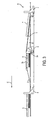
- FIG. 3 is a side plan view of the collating apparatus
- FIG. 4 of the drawings is a top plan view of the collating apparatus
- FIG. 5 is a partial side plan view of another example of a collating apparatus.
- FIG. 6 is a side plan view of another example of a collating apparatus.
- the present collating apparatus is configured to function with a conventional in-line mail processing.
- collating apparatus 20 is situated between a downstream inserter station 22 and upstream insert feeders 21 within an in-line mail processing system 100.
- Directional arrow C indicates the direction of documents traveling along the in-line mail processing system 400.
- Additional mail processing components positioned downstream from inserter station 22 may include for example a sealer, envelope feeder, diverter, conveyor, and flat conveyor, all of which are well known in the industry and are not shown in the FIG. 1 for illustrative simplicity.
- Additional components positioned upstream from inserter 22 may include conventional input stations (not shown) and the like.
- the collating apparatus 20 is adapted to advance sequentially delivered document sets, one or more of which may be previously collated, and assemble the document sets into a single collated packet for mailing.
- Each document set includes one or more sheets or pages of paper material or other articles intended for mail delivery.
- Non-limiting examples of mailable materials, other than sheets of paper include compact discs (CD) and digital video discs (DVD).
- CD compact discs
- DVD digital video discs
- a second set of fixed-position pusher pins 4 advances the trailing document set into trail edge registration with the previously deposited lead document set 8.
- the second set of fixed position pusher pins 4 removes and assembles both sets of documents 7 and 8 into a single trail edge registered mail packet 9.
- the single trail edge registered mail packet 9 is then advanced by the second set of fixed position pusher pins for further processing, e.g. at an envelope inserting or stuffing station.
- the inserting or stuffing station is adapted for receiving, supporting, and sequentially feeding envelopes, one at a time, into the document feed path at an area adjacent the downstream portion of the conveyor.
- the stuffing station is constructed for positioning envelopes, one at a time, for receiving therein a collated set of documents. After each envelope is sequentially stuffed by having a collated set of documents inserted into the fixed envelope, the stuffed envelope is conveyed to the downstream end of the raceway conveyor for additional handling.
- Collating apparatus 20 includes a substantially elongated synchronous raceway conveyor 25 having an upper surface 26.
- Raceway conveyor 25 is configured to advance a plurality of document sets consecutively along the substantially horizontal conveying pathway 27 from an initial upstream position A to a downstream position B in the direction indicated by directional arrow C.
- the plurality of document sets is merged into a combined mail packet before being inserted into an envelope at a downstream inserter.
- Each document set includes one or more sheets or pages of paper material or other article(s) intended for mail delivery.
- the components of the mail packet 9 to be assembled are transported along the conveying pathway 27 of collating apparatus 20 as a series of sequential document sets which can be selectively combined in a predetermined order at a collation station.
- FIG. 2 A prime document set 7 and a second set 8 are depicted in FIG. 2.
- the prime document set is the address bearing document.
- the second document set 8 can include one or more pages of inserts that were previously assembled in a conventional fashion as a synchronized conveyor (not shown) passes under upstream insert feeders 21 (depicted in FIG. 1).
- FIG. 5 depicts the conveying pathway 27 is formed with a pair of parallel, spaced part, longitudinally extending slots 27b through which drop away pusher pins 5 and fixed position pusher pins 4 extend.
- pusher pins 4, 5 are coupled to and move along a grooved track 12 positioned below the longitudinally extending slots 27b and advanced with a chain (not shown).
- Fixed position pusher pins 4 are fastened to a chain by way of pins and clips, such as E-clips). The clips retain the pins and pick it to the chain.
- An anti-rotation pin is used with the fixed position pusher pins 4 as well such that the position of the pin is maintained or fixed.
- the drop away pusher pins 5 are secured to the chain by way of a mounting pin, such as one or more pick mounting pins.
- the pusher pins 4, 5 are adapted to intercept, contact, push and advance the document sets downstream along the conveying pathway 27.
- Document sets 7, 8 are delivered to the synchronous raceway conveyor 25 by conventional mail processing methods from upstream insert feeders 21.
- each document set 8 is conveyed by the drop away pusher pins 5.
- Drop away pusher pins 5 are designed to drop away at the precise moment that a document set 8 is transported downstream to collation station 2a, as shown in FIG. 3.
- an actuating deck plate 1 is in the horizontal or down position, so the collation point for document set 8 is at the raceway conveyor 25 level.
- the advancement of document set 8 is halted at the point when the drop away pusher pins 5 pivot downward from an upright drive position down to a position below the synchronous raceway conveyor 25 and out of contact with document set 8.
- the mechanism is designed such that once support is removed from the "foot" 5b of the drop away pusher pin, the weight of the foot 5b causes the drop away pusher pin to pivot backwards (rotate clockwise) by way of gravity. In other words, the weight of the foot 5b causes the drop away pusher pin 5 to rotate clockwise to a position below the synchronous raceway conveyor 25.
- This mechanism can be augmented by a torsion spring for faster rotation drop away pusher pin 5. As a result of the drop away pusher pin 5 rotating below the synchronous raceway conveyor 25, and out of contact with document set 8, document set 8 is deposited at collation station 2a.
- Drop away pusher pins 5 are designed to rotate backwards at the precise moment that document set 8 is delivered downstream to collation station 2a. Drop away pusher pins 5 rotate backwards once they clear edge 10 of the raceway conveyor 25, as illustrated in FIG. 5. Drop away pusher pins 5 are spaced from each other along the chain(s) of the conveying pathway 27. Similarly, fixed-position pusher pins 4 are longitudinally spaced from each other along the chain(s) of the conveying pathway 27 and are positioned intermediate the drop away pusher pins 5. Meanwhile, document set 7 is immediately trailing document set 8 and is advanced by the fixed-position pusher pins 4.
- Document set 7 is next transported down the fixed ramp 3 and merged, trailing end registered, with document set 8.
- the document set 7 can be selectively (as determined by operator selection or by the design implementation) positioned either on top of the insert document set 8 or, alternatively, underneath the insert document set 8.
- the selectivity can be fixed, such that the packet being pushed by the drop away pusher pin is always deposited on the bottom of the assembled packet. Alternatively, the selection can be specified by the operator as part of the normal "job" configuration that is necessary for a typical inserter system.
- the now assembled mail packet 9 is next transported along the conveying pathway 27 for additional processing at an envelope inserting station positioned downstream.
- the actuating deck plate 1 is controlled by a two-state actuator such as a solenoid, a pneumatically operated cylinder or the like.
- the actuating deck plate as depicted in FIG. 2, is comprised of three platforms connected by a common mechanical linkage such that all of the deck plates are positioned by a common actuator.
- a solenoid 6 is depicted which is adapted to raise one end of the actuating deck plate 1 to substantially the same height as platform 2b.
- Platform 2b is an elevated platform mounted on the upper surface of the raceway conveyor downstream from the actuating deck plate 1.
- document set 7 is advanced with fixed-position pusher pins 4 across the top surface of the elevated actuating plate 1, such that document set 7 will continue to advance on and across the surface of platform 2b.
- the collating device 20 comprises a conveying pathway that is formed with a single, spaced part, longitudinally extending slot through which drop away pusher pins 5 and fixed position pusher pins 4 extend.
- a single column of alternating drop away and fixed position pushers pins extend through the longitudinally extending slot of the conveying pathway.
- the actuating deck plate is comprised of two deck platforms with the conveying pathway running between the two deck platforms. The actuating deck plate is raised and lowered with a two-state actuator. First and second document sets are advanced in a similar manner as previously discussed. As the fixed-position pusher pin reaches the collation point, it will come into contact with the document set already deposited at the collation point via the drop away pusher pin.
- the fixed-position pusher pin simultaneously advances both document sets.
- the second document set is transported down a fixed ramp from the platform and merged with the first document set.
- the platform is positioned above the conveying pathway and over the collation point and is separated with a gap through its middle section to permit the fixed position pusher pin to pass through platform.
- the collating apparatus 20 can accommodate multiple document sets 7. As shown in FIG. 6, a first document set 7 (not shown) is advanced with a drop away pusher pin 5' and a second trailing document set 7 (not shown) is advanced with drop away pusher pins 5".
- the number of consecutive drop away pusher pins will correspond with the number of levels of platform (2b', 2b", etc.) above the raceway level.
- An actuator with finer resolution such as a stepper motor and drive linkage are necessary to accommodate multiple document sets in this example.
- a document set that is being advanced by a drop away pusher pin is capable of being deposited on any platform (2b', 2b", etc.).
- Each platform level can accept one document set delivered by a drop away pusher pin.
- the actuator is designed to insure that the actuating deck plate is raised to a proper position at each level of the platform.
- the association of a document set to a specific platform level can be fixed or selective by a configuration "job".
- the operation of the present collating apparatus 20 can be controlled by means of a microprocessor 100 which may adjust the speed of a variable speed motor 200 in accordance with a desired program.
- the motor 200 as seen in FIG. 2, is operable to drive the chains that move the fixed-position and drop away pusher pins.
- the microprocessor 100 is adapted to operate other components of the collating apparatus 20, including the two-state actuator, in accordance with the speed chosen for operating the motor 200.
- One or more sensing devices 300 including conventional photocell, infrared-type or other conventional sensing devices, that are capable of detecting preset conditions including limit errors, read errors, integrity errors and handling errors can be included with the collating apparatus 20. Sensing device(s) 300 are linked through wiring to microprocessor 100.
Landscapes
- Collation Of Sheets And Webs (AREA)
Applications Claiming Priority (1)
| Application Number | Priority Date | Filing Date | Title |
|---|---|---|---|
| US11/240,604 US7396006B2 (en) | 2005-10-03 | 2005-10-03 | Apparatus for assembly of document sets into a single collated packet |
Publications (3)
| Publication Number | Publication Date |
|---|---|
| EP1770042A2 true EP1770042A2 (fr) | 2007-04-04 |
| EP1770042A3 EP1770042A3 (fr) | 2007-04-11 |
| EP1770042B1 EP1770042B1 (fr) | 2009-03-25 |
Family
ID=37719423
Family Applications (1)
| Application Number | Title | Priority Date | Filing Date |
|---|---|---|---|
| EP06018903A Not-in-force EP1770042B1 (fr) | 2005-10-03 | 2006-09-08 | Appareil d'assemblage de documents dans un seul paquet collationné |
Country Status (3)
| Country | Link |
|---|---|
| US (1) | US7396006B2 (fr) |
| EP (1) | EP1770042B1 (fr) |
| DE (1) | DE602006005876D1 (fr) |
Cited By (6)
| Publication number | Priority date | Publication date | Assignee | Title |
|---|---|---|---|---|
| EP1911710A1 (fr) * | 2006-10-12 | 2008-04-16 | Bowe Bell + Howell Company | Appareil et procédé de mise à disposition et traitement des documents |
| US7396006B2 (en) | 2005-10-03 | 2008-07-08 | Bowe Bell + Howell Company | Apparatus for assembly of document sets into a single collated packet |
| US7454882B2 (en) | 2006-10-12 | 2008-11-25 | Bowe Bell + Howell Company | Methods for variably opening envelopes |
| US7607653B2 (en) | 2006-10-12 | 2009-10-27 | Bowe Bell + Howell Company | Systems and methods for maintaining the density of grouped sheet articles |
| US7637490B2 (en) | 2005-10-03 | 2009-12-29 | Bowe Bell + Howell Company | Inserting systems and methods |
| US7662080B2 (en) | 2006-10-12 | 2010-02-16 | Bowe Bell & Howell | Crease roller apparatuses and methods for using same |
Families Citing this family (6)
| Publication number | Priority date | Publication date | Assignee | Title |
|---|---|---|---|---|
| JP2003075976A (ja) * | 2001-09-07 | 2003-03-12 | Noritsu Koki Co Ltd | 写真処理システム |
| US20080088083A1 (en) * | 2006-10-12 | 2008-04-17 | Bowe Bell + Howell Company | Apparatuses and methods for registering sheet articles |
| GB2472248A (en) * | 2009-07-31 | 2011-02-02 | Neopost Technologies | A paper handling apparatus |
| JP5631172B2 (ja) * | 2009-12-16 | 2014-11-26 | キヤノン株式会社 | シート処理装置及び画像形成装置 |
| US8371568B2 (en) * | 2010-05-25 | 2013-02-12 | Xerox Corporation | Actuator and dual bin size belt system for multiple size media transport |
| CN107187795B (zh) * | 2016-03-14 | 2023-02-28 | 北京大森长空包装机械有限公司 | 可自动变换节距的物料传输装置 |
Citations (3)
| Publication number | Priority date | Publication date | Assignee | Title |
|---|---|---|---|---|
| EP0113011A1 (fr) | 1982-12-10 | 1984-07-11 | Harris Graphics Corporation | Dispositif pour dévier des feuilles dans un appareil de traitement de feuilles |
| US4541764A (en) | 1984-05-24 | 1985-09-17 | Pitney Bowes Inc. | Document stacking and conveying apparatus |
| DE20320537U1 (de) | 2003-01-29 | 2004-10-07 | Klasen, Bernhard | Zusammentragmaschine |
Family Cites Families (18)
| Publication number | Priority date | Publication date | Assignee | Title |
|---|---|---|---|---|
| US3207017A (en) | 1964-02-28 | 1965-09-21 | Chicago Machinery Lab Inc | Method and apparatus for trimming and splitting double books into separate books |
| US3275118A (en) | 1965-04-15 | 1966-09-27 | Chicago Machinery Lab Inc | Trimming machine |
| US4071997A (en) * | 1976-04-27 | 1978-02-07 | Gunther Business Systems, Inc. | Mechanism and method of making an envelope |
| US4299073A (en) * | 1979-11-09 | 1981-11-10 | American Express Company | Machine and method for packaging travelers checks |
| US4694632A (en) * | 1985-06-24 | 1987-09-22 | Gunther International, Ltd. | Mechanism for folding an envelope around an insert |
| US4694631A (en) * | 1985-06-24 | 1987-09-22 | Gunther International, Ltd. | Mechanism for folding an envelope around an insert |
| US4787192A (en) * | 1985-06-24 | 1988-11-29 | Gunther International, Ltd. | Mechanism for folding an envelope around an insert |
| FR2587015B1 (fr) | 1985-09-11 | 1988-07-08 | Ordibel | Transporteur pour machine a assembler des feuilles de papier et machines en faisant application |
| US4753429A (en) * | 1986-11-13 | 1988-06-28 | Pitney Bowes Inc. | Collating station for inserting machine |
| US5255498A (en) * | 1990-11-02 | 1993-10-26 | Pitney Bowes Inc. | Envelope stuffing apparatus |
| US5581972A (en) * | 1995-07-03 | 1996-12-10 | Pitney Bowes Inc. | Container opening apparatus |
| IT1308720B1 (it) * | 1999-06-08 | 2002-01-10 | Tecnau Srl | Sequenziatore dinamico per fogli di carta stampati |
| US6748294B1 (en) * | 2000-10-23 | 2004-06-08 | Bowe Bell + Howell Postal Systems Company | Flats bundle collator |
| GB2389574B (en) * | 2002-06-14 | 2005-07-06 | Pfe Internat Ltd | Collator |
| US7014730B2 (en) | 2002-08-26 | 2006-03-21 | Longford Equipment International Limited | Selective card diverting |
| US7396006B2 (en) | 2005-10-03 | 2008-07-08 | Bowe Bell + Howell Company | Apparatus for assembly of document sets into a single collated packet |
| US7637490B2 (en) | 2005-10-03 | 2009-12-29 | Bowe Bell + Howell Company | Inserting systems and methods |
| US7607649B2 (en) | 2005-10-03 | 2009-10-27 | Bowe Bell + Howell Company | Apparatuses and methods for staging and processing documents for sheet processing |
-
2005
- 2005-10-03 US US11/240,604 patent/US7396006B2/en not_active Expired - Fee Related
-
2006
- 2006-09-08 EP EP06018903A patent/EP1770042B1/fr not_active Not-in-force
- 2006-09-08 DE DE602006005876T patent/DE602006005876D1/de active Active
Patent Citations (3)
| Publication number | Priority date | Publication date | Assignee | Title |
|---|---|---|---|---|
| EP0113011A1 (fr) | 1982-12-10 | 1984-07-11 | Harris Graphics Corporation | Dispositif pour dévier des feuilles dans un appareil de traitement de feuilles |
| US4541764A (en) | 1984-05-24 | 1985-09-17 | Pitney Bowes Inc. | Document stacking and conveying apparatus |
| DE20320537U1 (de) | 2003-01-29 | 2004-10-07 | Klasen, Bernhard | Zusammentragmaschine |
Cited By (7)
| Publication number | Priority date | Publication date | Assignee | Title |
|---|---|---|---|---|
| US7396006B2 (en) | 2005-10-03 | 2008-07-08 | Bowe Bell + Howell Company | Apparatus for assembly of document sets into a single collated packet |
| US7607649B2 (en) | 2005-10-03 | 2009-10-27 | Bowe Bell + Howell Company | Apparatuses and methods for staging and processing documents for sheet processing |
| US7637490B2 (en) | 2005-10-03 | 2009-12-29 | Bowe Bell + Howell Company | Inserting systems and methods |
| EP1911710A1 (fr) * | 2006-10-12 | 2008-04-16 | Bowe Bell + Howell Company | Appareil et procédé de mise à disposition et traitement des documents |
| US7454882B2 (en) | 2006-10-12 | 2008-11-25 | Bowe Bell + Howell Company | Methods for variably opening envelopes |
| US7607653B2 (en) | 2006-10-12 | 2009-10-27 | Bowe Bell + Howell Company | Systems and methods for maintaining the density of grouped sheet articles |
| US7662080B2 (en) | 2006-10-12 | 2010-02-16 | Bowe Bell & Howell | Crease roller apparatuses and methods for using same |
Also Published As
| Publication number | Publication date |
|---|---|
| US20070075475A1 (en) | 2007-04-05 |
| DE602006005876D1 (de) | 2009-05-07 |
| EP1770042A3 (fr) | 2007-04-11 |
| US7396006B2 (en) | 2008-07-08 |
| EP1770042B1 (fr) | 2009-03-25 |
Similar Documents
| Publication | Publication Date | Title |
|---|---|---|
| EP1911710B1 (fr) | Appareil et procédé de mise à disposition et traitement des documents | |
| US7396006B2 (en) | Apparatus for assembly of document sets into a single collated packet | |
| AU2009288644B2 (en) | Conveying apparatus for envelopes and related methods | |
| US5244199A (en) | Stream feeding machine for holding and delivering signatures | |
| AU2009288641B2 (en) | Envelope conveying and positioning apparatus and related methods | |
| AU2007209736B2 (en) | Apparatus for collating flat objects and for conveying the collated objects further | |
| US7475522B2 (en) | Envelope filling machine | |
| US7637490B2 (en) | Inserting systems and methods | |
| WO2010118001A2 (fr) | Appareil d'accumulation pour des objets discrets en papier ou sous forme de film et procédés associés | |
| US6915184B2 (en) | Collator | |
| AU2009288642B2 (en) | Inserting apparatus for discrete objects into envelopes and related methods | |
| GB2143216A (en) | Method of and apparatus for producing stacks of flexible flat products especially printed products | |
| US7905076B2 (en) | Apparatus and method for conveying envelopes in a mailpiece insertion system | |
| US20060097440A1 (en) | Method and apparatus for placing or inserting printed supplements into printed core products | |
| WO2010118017A1 (fr) | Appareil de transport avec élément non obstructif et procédés associés | |
| JPH08268629A (ja) | 搬送用紙区分け装置 |
Legal Events
| Date | Code | Title | Description |
|---|---|---|---|
| PUAI | Public reference made under article 153(3) epc to a published international application that has entered the european phase |
Free format text: ORIGINAL CODE: 0009012 |
|
| PUAL | Search report despatched |
Free format text: ORIGINAL CODE: 0009013 |
|
| 17P | Request for examination filed |
Effective date: 20060908 |
|
| AK | Designated contracting states |
Kind code of ref document: A2 Designated state(s): AT BE BG CH CY CZ DE DK EE ES FI FR GB GR HU IE IS IT LI LT LU LV MC NL PL PT RO SE SI SK TR |
|
| AX | Request for extension of the european patent |
Extension state: AL BA HR MK YU |
|
| AK | Designated contracting states |
Kind code of ref document: A3 Designated state(s): AT BE BG CH CY CZ DE DK EE ES FI FR GB GR HU IE IS IT LI LT LU LV MC NL PL PT RO SE SI SK TR |
|
| AX | Request for extension of the european patent |
Extension state: AL BA HR MK YU |
|
| 17Q | First examination report despatched |
Effective date: 20071015 |
|
| AKX | Designation fees paid |
Designated state(s): CH DE FR IT LI |
|
| GRAP | Despatch of communication of intention to grant a patent |
Free format text: ORIGINAL CODE: EPIDOSNIGR1 |
|
| GRAS | Grant fee paid |
Free format text: ORIGINAL CODE: EPIDOSNIGR3 |
|
| GRAA | (expected) grant |
Free format text: ORIGINAL CODE: 0009210 |
|
| AK | Designated contracting states |
Kind code of ref document: B1 Designated state(s): CH DE FR IT LI |
|
| REG | Reference to a national code |
Ref country code: CH Ref legal event code: NV Representative=s name: BOVARD AG PATENTANWAELTE Ref country code: CH Ref legal event code: EP |
|
| REF | Corresponds to: |
Ref document number: 602006005876 Country of ref document: DE Date of ref document: 20090507 Kind code of ref document: P |
|
| PLBE | No opposition filed within time limit |
Free format text: ORIGINAL CODE: 0009261 |
|
| STAA | Information on the status of an ep patent application or granted ep patent |
Free format text: STATUS: NO OPPOSITION FILED WITHIN TIME LIMIT |
|
| 26N | No opposition filed |
Effective date: 20091229 |
|
| PGFP | Annual fee paid to national office [announced via postgrant information from national office to epo] |
Ref country code: IT Payment date: 20090930 Year of fee payment: 4 |
|
| REG | Reference to a national code |
Ref country code: CH Ref legal event code: PFA Owner name: BOWE BELL + HOWELL COMPANY Free format text: BOWE BELL + HOWELL COMPANY#3791 S. ALSTON AVENUE#DURHAM NC 27713-1803 (US) -TRANSFER TO- BOWE BELL + HOWELL COMPANY#3791 S. ALSTON AVENUE#DURHAM NC 27713-1803 (US) |
|
| PG25 | Lapsed in a contracting state [announced via postgrant information from national office to epo] |
Ref country code: IT Free format text: LAPSE BECAUSE OF NON-PAYMENT OF DUE FEES Effective date: 20100908 |
|
| REG | Reference to a national code |
Ref country code: CH Ref legal event code: PUE Owner name: BELL AND HOWELL, LLC Free format text: BOWE BELL + HOWELL COMPANY#3791 S. ALSTON AVENUE#DURHAM NC 27713-1803 (US) -TRANSFER TO- BELL AND HOWELL, LLC#3791 S. ALSTON AVENUE#DURHAM, NORTH CAROLINA 27713 (US) Ref country code: CH Ref legal event code: NV Representative=s name: SERVOPATENT GMBH |
|
| REG | Reference to a national code |
Ref country code: FR Ref legal event code: CD Owner name: BELL AND HOWELL, LLC, US Effective date: 20120420 Ref country code: FR Ref legal event code: TP Owner name: BELL AND HOWELL, LLC, US Effective date: 20120420 Ref country code: FR Ref legal event code: CA Effective date: 20120420 |
|
| REG | Reference to a national code |
Ref country code: DE Ref legal event code: R082 Ref document number: 602006005876 Country of ref document: DE Representative=s name: BRAUN-DULLAEUS PANNEN PATENT- UND RECHTSANWAEL, DE |
|
| PGFP | Annual fee paid to national office [announced via postgrant information from national office to epo] |
Ref country code: FR Payment date: 20130919 Year of fee payment: 8 |
|
| PGFP | Annual fee paid to national office [announced via postgrant information from national office to epo] |
Ref country code: CH Payment date: 20140929 Year of fee payment: 9 |
|
| PGFP | Annual fee paid to national office [announced via postgrant information from national office to epo] |
Ref country code: DE Payment date: 20140929 Year of fee payment: 9 |
|
| REG | Reference to a national code |
Ref country code: FR Ref legal event code: ST Effective date: 20150529 |
|
| PG25 | Lapsed in a contracting state [announced via postgrant information from national office to epo] |
Ref country code: FR Free format text: LAPSE BECAUSE OF NON-PAYMENT OF DUE FEES Effective date: 20140930 |
|
| REG | Reference to a national code |
Ref country code: DE Ref legal event code: R119 Ref document number: 602006005876 Country of ref document: DE |
|
| REG | Reference to a national code |
Ref country code: CH Ref legal event code: PL |
|
| PG25 | Lapsed in a contracting state [announced via postgrant information from national office to epo] |
Ref country code: LI Free format text: LAPSE BECAUSE OF NON-PAYMENT OF DUE FEES Effective date: 20150930 Ref country code: CH Free format text: LAPSE BECAUSE OF NON-PAYMENT OF DUE FEES Effective date: 20150930 Ref country code: DE Free format text: LAPSE BECAUSE OF NON-PAYMENT OF DUE FEES Effective date: 20160401 |