EP1770326A2 - Réservoir pour liquide cryogénique - Google Patents
Réservoir pour liquide cryogénique Download PDFInfo
- Publication number
- EP1770326A2 EP1770326A2 EP06254948A EP06254948A EP1770326A2 EP 1770326 A2 EP1770326 A2 EP 1770326A2 EP 06254948 A EP06254948 A EP 06254948A EP 06254948 A EP06254948 A EP 06254948A EP 1770326 A2 EP1770326 A2 EP 1770326A2
- Authority
- EP
- European Patent Office
- Prior art keywords
- vapour
- cryogenic liquid
- vessel
- storage vessel
- liquid
- Prior art date
- Legal status (The legal status is an assumption and is not a legal conclusion. Google has not performed a legal analysis and makes no representation as to the accuracy of the status listed.)
- Granted
Links
- 239000007788 liquid Substances 0.000 title claims abstract description 184
- 238000012856 packing Methods 0.000 claims abstract description 62
- 239000012530 fluid Substances 0.000 claims abstract description 8
- 238000004891 communication Methods 0.000 claims abstract description 5
- 238000000034 method Methods 0.000 claims description 25
- 230000008569 process Effects 0.000 claims description 17
- 238000001816 cooling Methods 0.000 claims description 10
- 239000003507 refrigerant Substances 0.000 claims description 4
- 238000005086 pumping Methods 0.000 claims description 3
- 238000009833 condensation Methods 0.000 abstract description 11
- 230000005494 condensation Effects 0.000 abstract description 11
- 230000009471 action Effects 0.000 abstract description 4
- 239000003949 liquefied natural gas Substances 0.000 description 18
- MYMOFIZGZYHOMD-UHFFFAOYSA-N Dioxygen Chemical compound O=O MYMOFIZGZYHOMD-UHFFFAOYSA-N 0.000 description 8
- 238000013461 design Methods 0.000 description 7
- 239000007921 spray Substances 0.000 description 6
- 238000012546 transfer Methods 0.000 description 6
- 239000001257 hydrogen Substances 0.000 description 5
- 229910052739 hydrogen Inorganic materials 0.000 description 5
- 238000009413 insulation Methods 0.000 description 5
- 239000000463 material Substances 0.000 description 5
- UFHFLCQGNIYNRP-UHFFFAOYSA-N Hydrogen Chemical compound [H][H] UFHFLCQGNIYNRP-UHFFFAOYSA-N 0.000 description 4
- VNWKTOKETHGBQD-UHFFFAOYSA-N methane Chemical compound C VNWKTOKETHGBQD-UHFFFAOYSA-N 0.000 description 4
- 239000000203 mixture Substances 0.000 description 4
- 238000000926 separation method Methods 0.000 description 4
- 238000009834 vaporization Methods 0.000 description 4
- XKRFYHLGVUSROY-UHFFFAOYSA-N Argon Chemical compound [Ar] XKRFYHLGVUSROY-UHFFFAOYSA-N 0.000 description 2
- IJGRMHOSHXDMSA-UHFFFAOYSA-N Atomic nitrogen Chemical compound N#N IJGRMHOSHXDMSA-UHFFFAOYSA-N 0.000 description 2
- 239000007789 gas Substances 0.000 description 2
- 230000005484 gravity Effects 0.000 description 2
- 239000002184 metal Substances 0.000 description 2
- 239000003345 natural gas Substances 0.000 description 2
- 238000005057 refrigeration Methods 0.000 description 2
- 238000013459 approach Methods 0.000 description 1
- 229910052786 argon Inorganic materials 0.000 description 1
- 238000005265 energy consumption Methods 0.000 description 1
- 238000001704 evaporation Methods 0.000 description 1
- 230000008020 evaporation Effects 0.000 description 1
- 150000002431 hydrogen Chemical class 0.000 description 1
- 238000012986 modification Methods 0.000 description 1
- 230000004048 modification Effects 0.000 description 1
- 229910052757 nitrogen Inorganic materials 0.000 description 1
- 230000009467 reduction Effects 0.000 description 1
- 229920006395 saturated elastomer Polymers 0.000 description 1
- 230000007480 spreading Effects 0.000 description 1
- 230000003068 static effect Effects 0.000 description 1
- 238000013022 venting Methods 0.000 description 1
Images

Classifications
-
- F—MECHANICAL ENGINEERING; LIGHTING; HEATING; WEAPONS; BLASTING
- F17—STORING OR DISTRIBUTING GASES OR LIQUIDS
- F17C—VESSELS FOR CONTAINING OR STORING COMPRESSED, LIQUEFIED OR SOLIDIFIED GASES; FIXED-CAPACITY GAS-HOLDERS; FILLING VESSELS WITH, OR DISCHARGING FROM VESSELS, COMPRESSED, LIQUEFIED, OR SOLIDIFIED GASES
- F17C13/00—Details of vessels or of the filling or discharging of vessels
- F17C13/12—Arrangements or mounting of devices for preventing or minimising the effect of explosion ; Other safety measures
-
- F—MECHANICAL ENGINEERING; LIGHTING; HEATING; WEAPONS; BLASTING
- F17—STORING OR DISTRIBUTING GASES OR LIQUIDS
- F17C—VESSELS FOR CONTAINING OR STORING COMPRESSED, LIQUEFIED OR SOLIDIFIED GASES; FIXED-CAPACITY GAS-HOLDERS; FILLING VESSELS WITH, OR DISCHARGING FROM VESSELS, COMPRESSED, LIQUEFIED, OR SOLIDIFIED GASES
- F17C5/00—Methods or apparatus for filling containers with liquefied, solidified, or compressed gases under pressures
- F17C5/02—Methods or apparatus for filling containers with liquefied, solidified, or compressed gases under pressures for filling with liquefied gases
-
- B—PERFORMING OPERATIONS; TRANSPORTING
- B63—SHIPS OR OTHER WATERBORNE VESSELS; RELATED EQUIPMENT
- B63B—SHIPS OR OTHER WATERBORNE VESSELS; EQUIPMENT FOR SHIPPING
- B63B25/00—Load-accommodating arrangements, e.g. stowing, trimming; Vessels characterised thereby
- B63B25/02—Load-accommodating arrangements, e.g. stowing, trimming; Vessels characterised thereby for bulk goods
- B63B25/08—Load-accommodating arrangements, e.g. stowing, trimming; Vessels characterised thereby for bulk goods fluid
-
- F—MECHANICAL ENGINEERING; LIGHTING; HEATING; WEAPONS; BLASTING
- F17—STORING OR DISTRIBUTING GASES OR LIQUIDS
- F17C—VESSELS FOR CONTAINING OR STORING COMPRESSED, LIQUEFIED OR SOLIDIFIED GASES; FIXED-CAPACITY GAS-HOLDERS; FILLING VESSELS WITH, OR DISCHARGING FROM VESSELS, COMPRESSED, LIQUEFIED, OR SOLIDIFIED GASES
- F17C1/00—Pressure vessels, e.g. gas cylinder, gas tank, replaceable cartridge
-
- F—MECHANICAL ENGINEERING; LIGHTING; HEATING; WEAPONS; BLASTING
- F25—REFRIGERATION OR COOLING; COMBINED HEATING AND REFRIGERATION SYSTEMS; HEAT PUMP SYSTEMS; MANUFACTURE OR STORAGE OF ICE; LIQUEFACTION SOLIDIFICATION OF GASES
- F25J—LIQUEFACTION, SOLIDIFICATION OR SEPARATION OF GASES OR GASEOUS OR LIQUEFIED GASEOUS MIXTURES BY PRESSURE AND COLD TREATMENT OR BY BRINGING THEM INTO THE SUPERCRITICAL STATE
- F25J1/00—Processes or apparatus for liquefying or solidifying gases or gaseous mixtures
- F25J1/0002—Processes or apparatus for liquefying or solidifying gases or gaseous mixtures characterised by the fluid to be liquefied
- F25J1/0012—Primary atmospheric gases, e.g. air
- F25J1/0015—Nitrogen
-
- F—MECHANICAL ENGINEERING; LIGHTING; HEATING; WEAPONS; BLASTING
- F25—REFRIGERATION OR COOLING; COMBINED HEATING AND REFRIGERATION SYSTEMS; HEAT PUMP SYSTEMS; MANUFACTURE OR STORAGE OF ICE; LIQUEFACTION SOLIDIFICATION OF GASES
- F25J—LIQUEFACTION, SOLIDIFICATION OR SEPARATION OF GASES OR GASEOUS OR LIQUEFIED GASEOUS MIXTURES BY PRESSURE AND COLD TREATMENT OR BY BRINGING THEM INTO THE SUPERCRITICAL STATE
- F25J1/00—Processes or apparatus for liquefying or solidifying gases or gaseous mixtures
- F25J1/0002—Processes or apparatus for liquefying or solidifying gases or gaseous mixtures characterised by the fluid to be liquefied
- F25J1/0012—Primary atmospheric gases, e.g. air
- F25J1/0017—Oxygen
-
- F—MECHANICAL ENGINEERING; LIGHTING; HEATING; WEAPONS; BLASTING
- F25—REFRIGERATION OR COOLING; COMBINED HEATING AND REFRIGERATION SYSTEMS; HEAT PUMP SYSTEMS; MANUFACTURE OR STORAGE OF ICE; LIQUEFACTION SOLIDIFICATION OF GASES
- F25J—LIQUEFACTION, SOLIDIFICATION OR SEPARATION OF GASES OR GASEOUS OR LIQUEFIED GASEOUS MIXTURES BY PRESSURE AND COLD TREATMENT OR BY BRINGING THEM INTO THE SUPERCRITICAL STATE
- F25J1/00—Processes or apparatus for liquefying or solidifying gases or gaseous mixtures
- F25J1/0002—Processes or apparatus for liquefying or solidifying gases or gaseous mixtures characterised by the fluid to be liquefied
- F25J1/0012—Primary atmospheric gases, e.g. air
- F25J1/002—Argon
-
- F—MECHANICAL ENGINEERING; LIGHTING; HEATING; WEAPONS; BLASTING
- F25—REFRIGERATION OR COOLING; COMBINED HEATING AND REFRIGERATION SYSTEMS; HEAT PUMP SYSTEMS; MANUFACTURE OR STORAGE OF ICE; LIQUEFACTION SOLIDIFICATION OF GASES
- F25J—LIQUEFACTION, SOLIDIFICATION OR SEPARATION OF GASES OR GASEOUS OR LIQUEFIED GASEOUS MIXTURES BY PRESSURE AND COLD TREATMENT OR BY BRINGING THEM INTO THE SUPERCRITICAL STATE
- F25J1/00—Processes or apparatus for liquefying or solidifying gases or gaseous mixtures
- F25J1/0002—Processes or apparatus for liquefying or solidifying gases or gaseous mixtures characterised by the fluid to be liquefied
- F25J1/0022—Hydrocarbons, e.g. natural gas
-
- F—MECHANICAL ENGINEERING; LIGHTING; HEATING; WEAPONS; BLASTING
- F25—REFRIGERATION OR COOLING; COMBINED HEATING AND REFRIGERATION SYSTEMS; HEAT PUMP SYSTEMS; MANUFACTURE OR STORAGE OF ICE; LIQUEFACTION SOLIDIFICATION OF GASES
- F25J—LIQUEFACTION, SOLIDIFICATION OR SEPARATION OF GASES OR GASEOUS OR LIQUEFIED GASEOUS MIXTURES BY PRESSURE AND COLD TREATMENT OR BY BRINGING THEM INTO THE SUPERCRITICAL STATE
- F25J1/00—Processes or apparatus for liquefying or solidifying gases or gaseous mixtures
- F25J1/02—Processes or apparatus for liquefying or solidifying gases or gaseous mixtures requiring the use of refrigeration, e.g. of helium or hydrogen ; Details and kind of the refrigeration system used; Integration with other units or processes; Controlling aspects of the process
- F25J1/0243—Start-up or control of the process; Details of the apparatus used; Details of the refrigerant compression system used
- F25J1/0257—Construction and layout of liquefaction equipments, e.g. valves, machines
- F25J1/0258—Construction and layout of liquefaction equipments, e.g. valves, machines vertical layout of the equipments within in the cold box
-
- F—MECHANICAL ENGINEERING; LIGHTING; HEATING; WEAPONS; BLASTING
- F17—STORING OR DISTRIBUTING GASES OR LIQUIDS
- F17C—VESSELS FOR CONTAINING OR STORING COMPRESSED, LIQUEFIED OR SOLIDIFIED GASES; FIXED-CAPACITY GAS-HOLDERS; FILLING VESSELS WITH, OR DISCHARGING FROM VESSELS, COMPRESSED, LIQUEFIED, OR SOLIDIFIED GASES
- F17C2201/00—Vessel construction, in particular geometry, arrangement or size
- F17C2201/01—Shape
- F17C2201/0104—Shape cylindrical
- F17C2201/0109—Shape cylindrical with exteriorly curved end-piece
-
- F—MECHANICAL ENGINEERING; LIGHTING; HEATING; WEAPONS; BLASTING
- F17—STORING OR DISTRIBUTING GASES OR LIQUIDS
- F17C—VESSELS FOR CONTAINING OR STORING COMPRESSED, LIQUEFIED OR SOLIDIFIED GASES; FIXED-CAPACITY GAS-HOLDERS; FILLING VESSELS WITH, OR DISCHARGING FROM VESSELS, COMPRESSED, LIQUEFIED, OR SOLIDIFIED GASES
- F17C2201/00—Vessel construction, in particular geometry, arrangement or size
- F17C2201/01—Shape
- F17C2201/0104—Shape cylindrical
- F17C2201/0119—Shape cylindrical with flat end-piece
-
- F—MECHANICAL ENGINEERING; LIGHTING; HEATING; WEAPONS; BLASTING
- F17—STORING OR DISTRIBUTING GASES OR LIQUIDS
- F17C—VESSELS FOR CONTAINING OR STORING COMPRESSED, LIQUEFIED OR SOLIDIFIED GASES; FIXED-CAPACITY GAS-HOLDERS; FILLING VESSELS WITH, OR DISCHARGING FROM VESSELS, COMPRESSED, LIQUEFIED, OR SOLIDIFIED GASES
- F17C2201/00—Vessel construction, in particular geometry, arrangement or size
- F17C2201/03—Orientation
- F17C2201/032—Orientation with substantially vertical main axis
-
- F—MECHANICAL ENGINEERING; LIGHTING; HEATING; WEAPONS; BLASTING
- F17—STORING OR DISTRIBUTING GASES OR LIQUIDS
- F17C—VESSELS FOR CONTAINING OR STORING COMPRESSED, LIQUEFIED OR SOLIDIFIED GASES; FIXED-CAPACITY GAS-HOLDERS; FILLING VESSELS WITH, OR DISCHARGING FROM VESSELS, COMPRESSED, LIQUEFIED, OR SOLIDIFIED GASES
- F17C2201/00—Vessel construction, in particular geometry, arrangement or size
- F17C2201/05—Size
- F17C2201/052—Size large (>1000 m3)
-
- F—MECHANICAL ENGINEERING; LIGHTING; HEATING; WEAPONS; BLASTING
- F17—STORING OR DISTRIBUTING GASES OR LIQUIDS
- F17C—VESSELS FOR CONTAINING OR STORING COMPRESSED, LIQUEFIED OR SOLIDIFIED GASES; FIXED-CAPACITY GAS-HOLDERS; FILLING VESSELS WITH, OR DISCHARGING FROM VESSELS, COMPRESSED, LIQUEFIED, OR SOLIDIFIED GASES
- F17C2203/00—Vessel construction, in particular walls or details thereof
- F17C2203/03—Thermal insulations
-
- F—MECHANICAL ENGINEERING; LIGHTING; HEATING; WEAPONS; BLASTING
- F17—STORING OR DISTRIBUTING GASES OR LIQUIDS
- F17C—VESSELS FOR CONTAINING OR STORING COMPRESSED, LIQUEFIED OR SOLIDIFIED GASES; FIXED-CAPACITY GAS-HOLDERS; FILLING VESSELS WITH, OR DISCHARGING FROM VESSELS, COMPRESSED, LIQUEFIED, OR SOLIDIFIED GASES
- F17C2203/00—Vessel construction, in particular walls or details thereof
- F17C2203/06—Materials for walls or layers thereof; Properties or structures of walls or their materials
- F17C2203/0602—Wall structures; Special features thereof
- F17C2203/0612—Wall structures
- F17C2203/0614—Single wall
- F17C2203/0617—Single wall with one layer
-
- F—MECHANICAL ENGINEERING; LIGHTING; HEATING; WEAPONS; BLASTING
- F17—STORING OR DISTRIBUTING GASES OR LIQUIDS
- F17C—VESSELS FOR CONTAINING OR STORING COMPRESSED, LIQUEFIED OR SOLIDIFIED GASES; FIXED-CAPACITY GAS-HOLDERS; FILLING VESSELS WITH, OR DISCHARGING FROM VESSELS, COMPRESSED, LIQUEFIED, OR SOLIDIFIED GASES
- F17C2205/00—Vessel construction, in particular mounting arrangements, attachments or identifications means
- F17C2205/03—Fluid connections, filters, valves, closure means or other attachments
- F17C2205/0302—Fittings, valves, filters, or components in connection with the gas storage device
- F17C2205/0323—Valves
- F17C2205/0332—Safety valves or pressure relief valves
-
- F—MECHANICAL ENGINEERING; LIGHTING; HEATING; WEAPONS; BLASTING
- F17—STORING OR DISTRIBUTING GASES OR LIQUIDS
- F17C—VESSELS FOR CONTAINING OR STORING COMPRESSED, LIQUEFIED OR SOLIDIFIED GASES; FIXED-CAPACITY GAS-HOLDERS; FILLING VESSELS WITH, OR DISCHARGING FROM VESSELS, COMPRESSED, LIQUEFIED, OR SOLIDIFIED GASES
- F17C2205/00—Vessel construction, in particular mounting arrangements, attachments or identifications means
- F17C2205/03—Fluid connections, filters, valves, closure means or other attachments
- F17C2205/0302—Fittings, valves, filters, or components in connection with the gas storage device
- F17C2205/0352—Pipes
- F17C2205/0355—Insulation thereof
-
- F—MECHANICAL ENGINEERING; LIGHTING; HEATING; WEAPONS; BLASTING
- F17—STORING OR DISTRIBUTING GASES OR LIQUIDS
- F17C—VESSELS FOR CONTAINING OR STORING COMPRESSED, LIQUEFIED OR SOLIDIFIED GASES; FIXED-CAPACITY GAS-HOLDERS; FILLING VESSELS WITH, OR DISCHARGING FROM VESSELS, COMPRESSED, LIQUEFIED, OR SOLIDIFIED GASES
- F17C2221/00—Handled fluid, in particular type of fluid
- F17C2221/01—Pure fluids
- F17C2221/011—Oxygen
-
- F—MECHANICAL ENGINEERING; LIGHTING; HEATING; WEAPONS; BLASTING
- F17—STORING OR DISTRIBUTING GASES OR LIQUIDS
- F17C—VESSELS FOR CONTAINING OR STORING COMPRESSED, LIQUEFIED OR SOLIDIFIED GASES; FIXED-CAPACITY GAS-HOLDERS; FILLING VESSELS WITH, OR DISCHARGING FROM VESSELS, COMPRESSED, LIQUEFIED, OR SOLIDIFIED GASES
- F17C2221/00—Handled fluid, in particular type of fluid
- F17C2221/01—Pure fluids
- F17C2221/012—Hydrogen
-
- F—MECHANICAL ENGINEERING; LIGHTING; HEATING; WEAPONS; BLASTING
- F17—STORING OR DISTRIBUTING GASES OR LIQUIDS
- F17C—VESSELS FOR CONTAINING OR STORING COMPRESSED, LIQUEFIED OR SOLIDIFIED GASES; FIXED-CAPACITY GAS-HOLDERS; FILLING VESSELS WITH, OR DISCHARGING FROM VESSELS, COMPRESSED, LIQUEFIED, OR SOLIDIFIED GASES
- F17C2221/00—Handled fluid, in particular type of fluid
- F17C2221/01—Pure fluids
- F17C2221/014—Nitrogen
-
- F—MECHANICAL ENGINEERING; LIGHTING; HEATING; WEAPONS; BLASTING
- F17—STORING OR DISTRIBUTING GASES OR LIQUIDS
- F17C—VESSELS FOR CONTAINING OR STORING COMPRESSED, LIQUEFIED OR SOLIDIFIED GASES; FIXED-CAPACITY GAS-HOLDERS; FILLING VESSELS WITH, OR DISCHARGING FROM VESSELS, COMPRESSED, LIQUEFIED, OR SOLIDIFIED GASES
- F17C2221/00—Handled fluid, in particular type of fluid
- F17C2221/01—Pure fluids
- F17C2221/016—Noble gases (Ar, Kr, Xe)
-
- F—MECHANICAL ENGINEERING; LIGHTING; HEATING; WEAPONS; BLASTING
- F17—STORING OR DISTRIBUTING GASES OR LIQUIDS
- F17C—VESSELS FOR CONTAINING OR STORING COMPRESSED, LIQUEFIED OR SOLIDIFIED GASES; FIXED-CAPACITY GAS-HOLDERS; FILLING VESSELS WITH, OR DISCHARGING FROM VESSELS, COMPRESSED, LIQUEFIED, OR SOLIDIFIED GASES
- F17C2223/00—Handled fluid before transfer, i.e. state of fluid when stored in the vessel or before transfer from the vessel
- F17C2223/01—Handled fluid before transfer, i.e. state of fluid when stored in the vessel or before transfer from the vessel characterised by the phase
- F17C2223/0107—Single phase
- F17C2223/0123—Single phase gaseous, e.g. CNG, GNC
-
- F—MECHANICAL ENGINEERING; LIGHTING; HEATING; WEAPONS; BLASTING
- F17—STORING OR DISTRIBUTING GASES OR LIQUIDS
- F17C—VESSELS FOR CONTAINING OR STORING COMPRESSED, LIQUEFIED OR SOLIDIFIED GASES; FIXED-CAPACITY GAS-HOLDERS; FILLING VESSELS WITH, OR DISCHARGING FROM VESSELS, COMPRESSED, LIQUEFIED, OR SOLIDIFIED GASES
- F17C2223/00—Handled fluid before transfer, i.e. state of fluid when stored in the vessel or before transfer from the vessel
- F17C2223/01—Handled fluid before transfer, i.e. state of fluid when stored in the vessel or before transfer from the vessel characterised by the phase
- F17C2223/0146—Two-phase
- F17C2223/0153—Liquefied gas, e.g. LPG, GPL
- F17C2223/0161—Liquefied gas, e.g. LPG, GPL cryogenic, e.g. LNG, GNL, PLNG
-
- F—MECHANICAL ENGINEERING; LIGHTING; HEATING; WEAPONS; BLASTING
- F17—STORING OR DISTRIBUTING GASES OR LIQUIDS
- F17C—VESSELS FOR CONTAINING OR STORING COMPRESSED, LIQUEFIED OR SOLIDIFIED GASES; FIXED-CAPACITY GAS-HOLDERS; FILLING VESSELS WITH, OR DISCHARGING FROM VESSELS, COMPRESSED, LIQUEFIED, OR SOLIDIFIED GASES
- F17C2223/00—Handled fluid before transfer, i.e. state of fluid when stored in the vessel or before transfer from the vessel
- F17C2223/03—Handled fluid before transfer, i.e. state of fluid when stored in the vessel or before transfer from the vessel characterised by the pressure level
- F17C2223/033—Small pressure, e.g. for liquefied gas
-
- F—MECHANICAL ENGINEERING; LIGHTING; HEATING; WEAPONS; BLASTING
- F17—STORING OR DISTRIBUTING GASES OR LIQUIDS
- F17C—VESSELS FOR CONTAINING OR STORING COMPRESSED, LIQUEFIED OR SOLIDIFIED GASES; FIXED-CAPACITY GAS-HOLDERS; FILLING VESSELS WITH, OR DISCHARGING FROM VESSELS, COMPRESSED, LIQUEFIED, OR SOLIDIFIED GASES
- F17C2227/00—Transfer of fluids, i.e. method or means for transferring the fluid; Heat exchange with the fluid
- F17C2227/01—Propulsion of the fluid
- F17C2227/0121—Propulsion of the fluid by gravity
-
- F—MECHANICAL ENGINEERING; LIGHTING; HEATING; WEAPONS; BLASTING
- F17—STORING OR DISTRIBUTING GASES OR LIQUIDS
- F17C—VESSELS FOR CONTAINING OR STORING COMPRESSED, LIQUEFIED OR SOLIDIFIED GASES; FIXED-CAPACITY GAS-HOLDERS; FILLING VESSELS WITH, OR DISCHARGING FROM VESSELS, COMPRESSED, LIQUEFIED, OR SOLIDIFIED GASES
- F17C2227/00—Transfer of fluids, i.e. method or means for transferring the fluid; Heat exchange with the fluid
- F17C2227/01—Propulsion of the fluid
- F17C2227/0128—Propulsion of the fluid with pumps or compressors
- F17C2227/0135—Pumps
-
- F—MECHANICAL ENGINEERING; LIGHTING; HEATING; WEAPONS; BLASTING
- F17—STORING OR DISTRIBUTING GASES OR LIQUIDS
- F17C—VESSELS FOR CONTAINING OR STORING COMPRESSED, LIQUEFIED OR SOLIDIFIED GASES; FIXED-CAPACITY GAS-HOLDERS; FILLING VESSELS WITH, OR DISCHARGING FROM VESSELS, COMPRESSED, LIQUEFIED, OR SOLIDIFIED GASES
- F17C2227/00—Transfer of fluids, i.e. method or means for transferring the fluid; Heat exchange with the fluid
- F17C2227/03—Heat exchange with the fluid
- F17C2227/0337—Heat exchange with the fluid by cooling
- F17C2227/0339—Heat exchange with the fluid by cooling using the same fluid
-
- F—MECHANICAL ENGINEERING; LIGHTING; HEATING; WEAPONS; BLASTING
- F17—STORING OR DISTRIBUTING GASES OR LIQUIDS
- F17C—VESSELS FOR CONTAINING OR STORING COMPRESSED, LIQUEFIED OR SOLIDIFIED GASES; FIXED-CAPACITY GAS-HOLDERS; FILLING VESSELS WITH, OR DISCHARGING FROM VESSELS, COMPRESSED, LIQUEFIED, OR SOLIDIFIED GASES
- F17C2227/00—Transfer of fluids, i.e. method or means for transferring the fluid; Heat exchange with the fluid
- F17C2227/03—Heat exchange with the fluid
- F17C2227/0337—Heat exchange with the fluid by cooling
- F17C2227/0341—Heat exchange with the fluid by cooling using another fluid
- F17C2227/0355—Heat exchange with the fluid by cooling using another fluid in a closed loop
-
- F—MECHANICAL ENGINEERING; LIGHTING; HEATING; WEAPONS; BLASTING
- F17—STORING OR DISTRIBUTING GASES OR LIQUIDS
- F17C—VESSELS FOR CONTAINING OR STORING COMPRESSED, LIQUEFIED OR SOLIDIFIED GASES; FIXED-CAPACITY GAS-HOLDERS; FILLING VESSELS WITH, OR DISCHARGING FROM VESSELS, COMPRESSED, LIQUEFIED, OR SOLIDIFIED GASES
- F17C2227/00—Transfer of fluids, i.e. method or means for transferring the fluid; Heat exchange with the fluid
- F17C2227/03—Heat exchange with the fluid
- F17C2227/0367—Localisation of heat exchange
- F17C2227/0369—Localisation of heat exchange in or on a vessel
- F17C2227/0372—Localisation of heat exchange in or on a vessel in the gas
-
- F—MECHANICAL ENGINEERING; LIGHTING; HEATING; WEAPONS; BLASTING
- F17—STORING OR DISTRIBUTING GASES OR LIQUIDS
- F17C—VESSELS FOR CONTAINING OR STORING COMPRESSED, LIQUEFIED OR SOLIDIFIED GASES; FIXED-CAPACITY GAS-HOLDERS; FILLING VESSELS WITH, OR DISCHARGING FROM VESSELS, COMPRESSED, LIQUEFIED, OR SOLIDIFIED GASES
- F17C2250/00—Accessories; Control means; Indicating, measuring or monitoring of parameters
- F17C2250/03—Control means
-
- F—MECHANICAL ENGINEERING; LIGHTING; HEATING; WEAPONS; BLASTING
- F17—STORING OR DISTRIBUTING GASES OR LIQUIDS
- F17C—VESSELS FOR CONTAINING OR STORING COMPRESSED, LIQUEFIED OR SOLIDIFIED GASES; FIXED-CAPACITY GAS-HOLDERS; FILLING VESSELS WITH, OR DISCHARGING FROM VESSELS, COMPRESSED, LIQUEFIED, OR SOLIDIFIED GASES
- F17C2250/00—Accessories; Control means; Indicating, measuring or monitoring of parameters
- F17C2250/04—Indicating or measuring of parameters as input values
- F17C2250/0404—Parameters indicated or measured
- F17C2250/043—Pressure
-
- F—MECHANICAL ENGINEERING; LIGHTING; HEATING; WEAPONS; BLASTING
- F17—STORING OR DISTRIBUTING GASES OR LIQUIDS
- F17C—VESSELS FOR CONTAINING OR STORING COMPRESSED, LIQUEFIED OR SOLIDIFIED GASES; FIXED-CAPACITY GAS-HOLDERS; FILLING VESSELS WITH, OR DISCHARGING FROM VESSELS, COMPRESSED, LIQUEFIED, OR SOLIDIFIED GASES
- F17C2260/00—Purposes of gas storage and gas handling
- F17C2260/02—Improving properties related to fluid or fluid transfer
- F17C2260/021—Avoiding over pressurising
-
- F—MECHANICAL ENGINEERING; LIGHTING; HEATING; WEAPONS; BLASTING
- F17—STORING OR DISTRIBUTING GASES OR LIQUIDS
- F17C—VESSELS FOR CONTAINING OR STORING COMPRESSED, LIQUEFIED OR SOLIDIFIED GASES; FIXED-CAPACITY GAS-HOLDERS; FILLING VESSELS WITH, OR DISCHARGING FROM VESSELS, COMPRESSED, LIQUEFIED, OR SOLIDIFIED GASES
- F17C2260/00—Purposes of gas storage and gas handling
- F17C2260/03—Dealing with losses
- F17C2260/035—Dealing with losses of fluid
- F17C2260/036—Avoiding leaks
-
- F—MECHANICAL ENGINEERING; LIGHTING; HEATING; WEAPONS; BLASTING
- F17—STORING OR DISTRIBUTING GASES OR LIQUIDS
- F17C—VESSELS FOR CONTAINING OR STORING COMPRESSED, LIQUEFIED OR SOLIDIFIED GASES; FIXED-CAPACITY GAS-HOLDERS; FILLING VESSELS WITH, OR DISCHARGING FROM VESSELS, COMPRESSED, LIQUEFIED, OR SOLIDIFIED GASES
- F17C2265/00—Effects achieved by gas storage or gas handling
- F17C2265/01—Purifying the fluid
- F17C2265/015—Purifying the fluid by separating
- F17C2265/017—Purifying the fluid by separating different phases of a same fluid
-
- F—MECHANICAL ENGINEERING; LIGHTING; HEATING; WEAPONS; BLASTING
- F17—STORING OR DISTRIBUTING GASES OR LIQUIDS
- F17C—VESSELS FOR CONTAINING OR STORING COMPRESSED, LIQUEFIED OR SOLIDIFIED GASES; FIXED-CAPACITY GAS-HOLDERS; FILLING VESSELS WITH, OR DISCHARGING FROM VESSELS, COMPRESSED, LIQUEFIED, OR SOLIDIFIED GASES
- F17C2265/00—Effects achieved by gas storage or gas handling
- F17C2265/03—Treating the boil-off
- F17C2265/032—Treating the boil-off by recovery
- F17C2265/033—Treating the boil-off by recovery with cooling
- F17C2265/034—Treating the boil-off by recovery with cooling with condensing the gas phase
-
- F—MECHANICAL ENGINEERING; LIGHTING; HEATING; WEAPONS; BLASTING
- F17—STORING OR DISTRIBUTING GASES OR LIQUIDS
- F17C—VESSELS FOR CONTAINING OR STORING COMPRESSED, LIQUEFIED OR SOLIDIFIED GASES; FIXED-CAPACITY GAS-HOLDERS; FILLING VESSELS WITH, OR DISCHARGING FROM VESSELS, COMPRESSED, LIQUEFIED, OR SOLIDIFIED GASES
- F17C2265/00—Effects achieved by gas storage or gas handling
- F17C2265/06—Fluid distribution
- F17C2265/068—Distribution pipeline networks
-
- F—MECHANICAL ENGINEERING; LIGHTING; HEATING; WEAPONS; BLASTING
- F17—STORING OR DISTRIBUTING GASES OR LIQUIDS
- F17C—VESSELS FOR CONTAINING OR STORING COMPRESSED, LIQUEFIED OR SOLIDIFIED GASES; FIXED-CAPACITY GAS-HOLDERS; FILLING VESSELS WITH, OR DISCHARGING FROM VESSELS, COMPRESSED, LIQUEFIED, OR SOLIDIFIED GASES
- F17C2270/00—Applications
- F17C2270/01—Applications for fluid transport or storage
- F17C2270/0102—Applications for fluid transport or storage on or in the water
- F17C2270/0105—Ships
-
- F—MECHANICAL ENGINEERING; LIGHTING; HEATING; WEAPONS; BLASTING
- F17—STORING OR DISTRIBUTING GASES OR LIQUIDS
- F17C—VESSELS FOR CONTAINING OR STORING COMPRESSED, LIQUEFIED OR SOLIDIFIED GASES; FIXED-CAPACITY GAS-HOLDERS; FILLING VESSELS WITH, OR DISCHARGING FROM VESSELS, COMPRESSED, LIQUEFIED, OR SOLIDIFIED GASES
- F17C2270/00—Applications
- F17C2270/01—Applications for fluid transport or storage
- F17C2270/0134—Applications for fluid transport or storage placed above the ground
-
- F—MECHANICAL ENGINEERING; LIGHTING; HEATING; WEAPONS; BLASTING
- F25—REFRIGERATION OR COOLING; COMBINED HEATING AND REFRIGERATION SYSTEMS; HEAT PUMP SYSTEMS; MANUFACTURE OR STORAGE OF ICE; LIQUEFACTION SOLIDIFICATION OF GASES
- F25J—LIQUEFACTION, SOLIDIFICATION OR SEPARATION OF GASES OR GASEOUS OR LIQUEFIED GASEOUS MIXTURES BY PRESSURE AND COLD TREATMENT OR BY BRINGING THEM INTO THE SUPERCRITICAL STATE
- F25J2205/00—Processes or apparatus using other separation and/or other processing means
- F25J2205/30—Processes or apparatus using other separation and/or other processing means using a washing, e.g. "scrubbing" or bubble column for purification purposes
-
- F—MECHANICAL ENGINEERING; LIGHTING; HEATING; WEAPONS; BLASTING
- F25—REFRIGERATION OR COOLING; COMBINED HEATING AND REFRIGERATION SYSTEMS; HEAT PUMP SYSTEMS; MANUFACTURE OR STORAGE OF ICE; LIQUEFACTION SOLIDIFICATION OF GASES
- F25J—LIQUEFACTION, SOLIDIFICATION OR SEPARATION OF GASES OR GASEOUS OR LIQUEFIED GASEOUS MIXTURES BY PRESSURE AND COLD TREATMENT OR BY BRINGING THEM INTO THE SUPERCRITICAL STATE
- F25J2205/00—Processes or apparatus using other separation and/or other processing means
- F25J2205/90—Mixing of components
-
- F—MECHANICAL ENGINEERING; LIGHTING; HEATING; WEAPONS; BLASTING
- F25—REFRIGERATION OR COOLING; COMBINED HEATING AND REFRIGERATION SYSTEMS; HEAT PUMP SYSTEMS; MANUFACTURE OR STORAGE OF ICE; LIQUEFACTION SOLIDIFICATION OF GASES
- F25J—LIQUEFACTION, SOLIDIFICATION OR SEPARATION OF GASES OR GASEOUS OR LIQUEFIED GASEOUS MIXTURES BY PRESSURE AND COLD TREATMENT OR BY BRINGING THEM INTO THE SUPERCRITICAL STATE
- F25J2210/00—Processes characterised by the type or other details of the feed stream
- F25J2210/06—Splitting of the feed stream, e.g. for treating or cooling in different ways
-
- F—MECHANICAL ENGINEERING; LIGHTING; HEATING; WEAPONS; BLASTING
- F25—REFRIGERATION OR COOLING; COMBINED HEATING AND REFRIGERATION SYSTEMS; HEAT PUMP SYSTEMS; MANUFACTURE OR STORAGE OF ICE; LIQUEFACTION SOLIDIFICATION OF GASES
- F25J—LIQUEFACTION, SOLIDIFICATION OR SEPARATION OF GASES OR GASEOUS OR LIQUEFIED GASEOUS MIXTURES BY PRESSURE AND COLD TREATMENT OR BY BRINGING THEM INTO THE SUPERCRITICAL STATE
- F25J2245/00—Processes or apparatus involving steps for recycling of process streams
- F25J2245/90—Processes or apparatus involving steps for recycling of process streams the recycled stream being boil-off gas from storage
-
- F—MECHANICAL ENGINEERING; LIGHTING; HEATING; WEAPONS; BLASTING
- F25—REFRIGERATION OR COOLING; COMBINED HEATING AND REFRIGERATION SYSTEMS; HEAT PUMP SYSTEMS; MANUFACTURE OR STORAGE OF ICE; LIQUEFACTION SOLIDIFICATION OF GASES
- F25J—LIQUEFACTION, SOLIDIFICATION OR SEPARATION OF GASES OR GASEOUS OR LIQUEFIED GASEOUS MIXTURES BY PRESSURE AND COLD TREATMENT OR BY BRINGING THEM INTO THE SUPERCRITICAL STATE
- F25J2290/00—Other details not covered by groups F25J2200/00 - F25J2280/00
- F25J2290/34—Details about subcooling of liquids
-
- F—MECHANICAL ENGINEERING; LIGHTING; HEATING; WEAPONS; BLASTING
- F25—REFRIGERATION OR COOLING; COMBINED HEATING AND REFRIGERATION SYSTEMS; HEAT PUMP SYSTEMS; MANUFACTURE OR STORAGE OF ICE; LIQUEFACTION SOLIDIFICATION OF GASES
- F25J—LIQUEFACTION, SOLIDIFICATION OR SEPARATION OF GASES OR GASEOUS OR LIQUEFIED GASEOUS MIXTURES BY PRESSURE AND COLD TREATMENT OR BY BRINGING THEM INTO THE SUPERCRITICAL STATE
- F25J2290/00—Other details not covered by groups F25J2200/00 - F25J2280/00
- F25J2290/62—Details of storing a fluid in a tank
-
- Y—GENERAL TAGGING OF NEW TECHNOLOGICAL DEVELOPMENTS; GENERAL TAGGING OF CROSS-SECTIONAL TECHNOLOGIES SPANNING OVER SEVERAL SECTIONS OF THE IPC; TECHNICAL SUBJECTS COVERED BY FORMER USPC CROSS-REFERENCE ART COLLECTIONS [XRACs] AND DIGESTS
- Y02—TECHNOLOGIES OR APPLICATIONS FOR MITIGATION OR ADAPTATION AGAINST CLIMATE CHANGE
- Y02E—REDUCTION OF GREENHOUSE GAS [GHG] EMISSIONS, RELATED TO ENERGY GENERATION, TRANSMISSION OR DISTRIBUTION
- Y02E60/00—Enabling technologies; Technologies with a potential or indirect contribution to GHG emissions mitigation
- Y02E60/30—Hydrogen technology
- Y02E60/32—Hydrogen storage
Definitions
- the present invention relates to a storage vessel for cryogenic liquid and has particular application in both land-based and ship-board storage vessels.
- Cryogenic liquids such as liquefied natural gas (“LNG”), liquid argon (“LAR”), liquid nitrogen (“LIN”), liquid oxygen (“LOX”) or liquid hydrogen, are stored in insulated storage vessels to minimise the loss of liquid by vaporisation.
- LNG liquefied natural gas
- LAR liquid argon
- LIN liquid nitrogen
- LOX liquid oxygen
- cryogenic liquid it is often preferable economically to use very large, low pressure storage vessels to store cryogenic liquid.
- the largest storage vessels for LOX or LIN have a capacity of about 5000 m 3 and the largest storage vessels for LNG (usually found on ships in groups of up to 5 storage vessels) each have a capacity of about 40,000 m 3 .
- the scale of the problem of pressure build-up due to boil-off is relative to the size of the storage vessel.
- Another solution to combat boil-off from the storage vessel is to sub-cool sufficiently the liquid feed to the storage vessel to re-condense the boil-off vapour.
- the sub-cooled feed is brought into good mass and energy contact with generated vapour, equilibrium will not be achieved. Without equilibrium, either much of the vapour would still have to be vented or the amount of sub-cooling would have to be increased to increase the driving force for the vapour condensation.
- US-B-6470706 discloses a boil-off vapour condenser in which boil-off vapour is condensed by direct heat exchange against a liquefied gas. It is disclosed that the condenser has particular application in storage and distribution systems for LNG. In these systems, the LNG is stored in a storage tank. Boil-off LNG vapour is fed to a vapour condenser provided outside the storage tank where it is condensed by direct heat and mass transfer with LNG pumped from the storage tank. Heat and mass transfer may be provided using random packing (such as 2 inch (5 cm) Pall rings), structured packing, tray columns or spray elements. The condensed LNG vapour is then fed to high pressure pumps, from which it is then routed to a distribution pipeline.
- random packing such as 2 inch (5 cm) Pall rings
- a storage vessel for cryogenic liquid having a lower portion for storing said cryogenic liquid and a vapour space provided thereabove, said vessel having:
- condensation of boil-off vapour occurs due to direct heat exchange between the cryogenic liquid feed and the boil-off vapour. Therefore, complex and expensive indirect heat exchangers are not required.
- cryogenic liquid is drawn through the condenser by gravity thereby further simplifying the design.
- condensation action of boil-off vapour within the packed arrangement of vapour-liquid contact packing draws further boil-off vapour into the condenser. Therefore, there is no need to use piping or other equipment to feed boil-off vapour to the condenser as the condenser effectively feeds itself with boil-off vapour.
- the top end portion of the packed arrangement of vapour-liquid contact packing will typically be colder than the bottom end portion as the sub-cooled liquid is fed to the top end portion and warms as it descends through the condenser. In use, the top end portion of the packed arrangement is colder than the bottom end portion.
- the bottom end portion of the packed arrangement is also open to the vapour space, more boil-off vapour will condense at the top end portion rather than at the bottom end portion thereby drawing more boil-off vapour into the condenser at the top rather than at the bottom.
- cryogenic liquid to be stored in the storage vessel is not critical to the invention.
- the invention is intended to have application in the storage of any cryogenic liquid including LNG, LAR, LIN, LOX and liquid hydrogen.
- Storage vessels for cryogenic liquids usually have an enclosure wall, a base and a cover defining an interior that consists of a lower portion for receiving cryogenic liquid and a vapour space provided above said lower portion.
- Such vessels are usually insulated to reduce heat leak into the vessel as much as possible. However, no insulation is completely effective.
- Such storage vessels will normally have a vent that may be opened and closed as required to release a build up of excess pressure due vaporisation of cryogenic liquid caused by heat leaking into the storage vessel.
- the vent is usually controlled automatically using a pressure sensor to determine when the pressure exceeds a pre-determined safe limit and actuating means to operate the vent to release the excess pressure.
- the source of the cryogenic liquid feed may be independent of the vessel or may be the vessel itself.
- the vessel may be integrated with a cryogenic air separation process in which the cryogenic liquid feed (e.g. LIN, LOX or LAR) may be produced in the cryogenic air separation process, sub-cooled as required and then fed to the vessel as the cryogenic liquid feed.
- the vessel may be integrated with a gas liquefaction process in which the cryogenic liquid feed (e.g. LNG or liquid hydrogen) may be produced in the liquefaction process, sub-cooled as required and then fed to the vessel as the cryogenic liquid feed.
- cryogenic liquid feed e.g. LNG or liquid hydrogen
- cryogenic liquid may be removed from the vessel, sub-cooled externally and then recycled back to the vessel as the cryogenic liquid feed.
- cryogenic liquid feed may be particularly applicable in transportation applications where boil-off must be suppressed but where there is no net feed to the storage vessel.
- An example of a suitable transportation application would be ship-board storage vessels for LNG.
- the storage vessel may further comprise:
- conduit means are usually insulated piping.
- the cryogenic liquid feed is typically sub-cooled to reduce the temperature to below that for the boil-off vapour thereby driving the condensation action.
- the feed is usually sub-cooled to at least the extent necessary to reduce or eliminate the need to vent boil-off vapour. Increasing the sub-cooling increasing the driving force for condensing the vapour and thus the surface area of the packing can be reduced proportionately.
- the condenser may be mounted inside or outside the vessel.
- the condenser is contained within a container.
- the container has a top end portion and a bottom end portion, both of which are in fluid flow communication (e.g. via pipe work) with the vapour space of the vessel to allow entry of boil-off vapour into the packed arrangement of vapour-liquid contact packing and to allow condensed vapour (together with warmed cryogenic liquid) to be fed to the vapour space and, thus, to the lower portion of the vessel.
- a container and the associated pipe work are insulated to reduce heat leak into the condenser. If the condenser is outside the vessel, then it may be retro-fitted to an existing storage vessel.
- the condenser is mounted within the vapour space of the storage vessel.
- These embodiments have several advantages over the embodiments having external condensers. For example, by not having the condenser provided outside the vessel there is less opportunity for heat leaking into the vessel contributing to the boil-off problem. In addition, there is no need for the additional container, pipe work and extra insulation. Further, it is not necessary to enclose the condenser and, thus, vapour can enter the condenser from the side of the packing.
- the packing material may be random packing such a Pall rings but is preferably structured packing such as corrugated, perforated metal sheets.
- the packing material preferably has a high surface area.
- the surface area of the packing is typically greater than 100 m 2 /m 3 (m 2 surface area/m 3 packing volume), usually greater than 200 m 2 /m 3 and preferably greater than 400 m 2 /m 3 .
- a suitable upper limit for the surface area of the packing is 750 m 2 /m 3 .
- the packing material may be banded together to form the packed arrangement in the form of a "plug".
- the sheets are usually packed vertically in parallel.
- a plug would not require a pressure enclosure and substantially all of the packed arrangement would be open to the vapour space to allow entry of boil-off vapour to the packing from substantially any direction.
- the packed arrangement of vapour-liquid contact packing is contained within an enclosure. Random or structured packing may be used with an enclosure. Side portions of the packed arrangement may be closed to the vapour space if the enclosure does not have any apertures. However, preferably, at least a portion of the or at least one side of the packed arrangement is open to the vapour space though at least one aperture in the enclosure to allow entry of the vapour to the packing from the side.
- the bottom end portion may also be open to the vapour space. These embodiments are particularly preferred when the condenser is within the vapour space of the storage vessel.
- the bottom end portion of the packed arrangement is in fluid flow communication with the lower portion of the vessel as condensed vapour (as a mixture with warmed feed) drops under gravity through the vapour space to the lower portion of the vessel.
- the storage vessel further comprises conduit means for feeding condensed vapour (as a mixture with warmed feed) from the bottom end portion of the packed arrangement to the lower portion of the storage vessel.
- conduit means may comprise a bottom enclosure (such as a bottom head), excluding vapour access from the vapour space to the bottom end portion of the packed arrangement, and piping to feed liquid collected in the bottom enclosure to the lower portion of the storage vessel.
- Adequate distribution of the cryogenic liquid over the top portion of the packed arrangement may be achieved by simply disgorging the liquid feed on to the top portion of the packing and relying on the inherent spreading capability of the packing.
- the vessel may further comprise a liquid distributor for distributing cryogenic liquid feed substantially uniformly over the top end portion of the packed arrangement of vapour-liquid contact packing.
- a liquid distributor for distributing cryogenic liquid feed substantially uniformly over the top end portion of the packed arrangement of vapour-liquid contact packing.
- Any conventional liquid distributor may be used.
- the distributor may be pressurised (in which case it would be a closed distributor such as a pipe, sparge or spray distributor) or it may be unpressurised (in which case it could be an open distributor such as a plate or trough distributor).
- the distributor is a plate distributor having vapour risers and a plurality of distribution apertures.
- the storage vessel may have more than one condenser and/or more than one inlet feeding a single condenser.
- An inlet may split to feed more than one condenser.
- the storage vessel has one condenser and one inlet for providing cryogenic liquid feed to said condenser.
- the inlet for the condenser may be the only inlet to the vessel. However, in an alternative embodiment, at least one additional inlet may be included. The or each additional inlet does not usually feed a condenser and, instead, is usually located for feeding cryogenic liquid directly to the lower portion of the vessel through the vapour space. In some embodiments, the feed to the vessel is split into two portions. The first portion is sub-cooled and fed to the condenser and the second portion is not sub-cooled and instead fed directly to the liquid stored in the lower portion of the vessel. The reduction in flow of the sub-cooled portion means that the total surface area of the packing can be reduced.
- the pressure in the vessel may be controlled by either varying the degree of sub-cooling of a single feed or the flow split between the sub-cooled and non sub-cooled feeds. Either option may be the primary pressure control system with a vent and pressure build-up vaporiser operating as a secondary system if the primary system is unable to keep the pressure within the desired range.
- the condenser of the present invention has particular application to storage vessels having a very large capacity, i.e. a capacity of over 500 m 3 .
- the upper limit of the capacity of storage vessels of the present invention may be as much as about 60,000 m 3 , e.g. about 40,000 m 3 (particularly in respect of ship board storage vessels for LNG) or about 5,000 m 3 (particularly in respect of storage vessels for LOX or LIN).
- the storage vessels of the present invention are preferably adapted for storage of low pressure cryogenic liquids, i.e. liquids having a pressure from about 0.5 bar vacuum (about 50 kPa absolute) to about 3 bar gauge (about 400 kPa absolute), preferably from about atmospheric pressure (about 100 kPa absolute) to about 0.5 bar gauge (about 150 kPa absolute).
- low pressure cryogenic liquids i.e. liquids having a pressure from about 0.5 bar vacuum (about 50 kPa absolute) to about 3 bar gauge (about 400 kPa absolute), preferably from about atmospheric pressure (about 100 kPa absolute) to about 0.5 bar gauge (about 150 kPa absolute).
- the device is usually designed to condense the maximum vapour generation from the following sources:
- the total vapour generation is V (in kg/s).
- the duty Q (in kW) is equal to V.dH where dH is the latent heat of evaporation of the stored fluid (in kJ/kg).
- the heat transfer coefficient can be estimated from relevant literature and the LMTD can be calculated from the sub-cooled liquid flow, the vapour flow and the liquid and vapour temperatures. A suitable margin can be applied to the required area A to give the actual area A*.
- the duty for a fixed surface area can be made insensitive to the heat transfer coefficient so that its value does not have to be accurately estimated.
- the cross-sectional area of the device, X (in m 2 ) should be determined using the design methods recommended for the chosen packing to ensure that vapour pressure drop is low and that the maximum vapour and liquid rates would not result in flooding of the packing if all the vapour entered at the bottom of the packing. Such a design method is well known in the art and will not be described further here.
- the liquid distributor should normally be sized so that the liquid flow over the packing is as uniform as possible.
- the design of such a distributor is well known and will not be described further here.
- the liquid may be fed at a single point on top of the packing.
- the effective surface area of the packing will need to be reduced to account for the surface that is not wetted by the liquid.
- a process for condensing boil-off vapour in a cryogenic liquid storage vessel said vessel having a lower portion for storing said cryogenic liquid, a vapour space provided thereabove and a condenser for condensing boil-off vapour by direct heat exchange with cryogenic liquid feed to the vessel, said condenser comprising vapour-liquid contact packing, said process comprising:
- the volume of the cryogenic liquid feed is sufficient to draw boil-off vapour into the packed arrangement of vapour-liquid contact packing.
- the process preferably further comprises distributing said sub-cooled cryogenic liquid substantially uniformly over the top end portion of the packed arrangement of vapour-liquid contact packing.
- the process may be integrated with a cryogenic air separation process producing the cryogenic liquid (e.g. LIN, LOX or LAR) or a liquefaction process producing the cryogenic liquid (e.g. LNG or liquid hydrogen).
- the process may further comprise removing cryogenic liquid from the storage vessel, pumping said liquid and then sub-cooling the pumped liquid to produce said sub-cooled cryogenic liquid feed.
- FIG. 1 shows an storage vessel 10 for cryogenic liquid according to the present invention.
- the storage vessel could be used to contain any cryogenic fluid such as LNG, LIN, LAR, LOX, etc.
- the storage vessel is insulated but the insulation is not shown in the Figure.
- the vessel 10 has a lower portion 12 for receiving the cryogenic liquid 14 and a vapour space 16 provided above the lower portion 12.
- a vent 18 is provided to release excess pressure build-up of boil-off vapour in the vapour space 16. Vent 18 is controlled by a pressure control device 20.
- a stream 22 of cryogenic liquid is removed from the vessel 10 and pumped to a higher pressure using pump 24 to produce a pumped stream 26 of cryogenic liquid.
- the pumped stream 26 is split into two portions. The first portion 28 is reduced in pressure across valve 30 and recycled to the vessel 10.
- the second portion 32 is removed as an outlet stream.
- the storage vessel 10 is used to deliver cryogenic liquid continuously or intermittently to a downstream unit (not shown) or for export.
- a condenser 34 is provided within the vapour space 16 of the vessel 10 and comprises a packed arrangement 36 of vapour-liquid contact packing.
- a stream 38 of cryogenic liquid feed is fed to the vessel 10 via inlet 40.
- Feed stream 38 has been sub-cooled (not shown) to at least the extent necessary to minimize or eliminate any boil-off vapour venting through the vent 18.
- Feed stream 38 is distributed substantially uniformly across the top end portion of the packed arrangement 36 of vapour-liquid contact packing using a liquid distributor (not shown).
- the sub-cooled liquid spreads over the packing to provide a large vapour-liquid interface surface area and condenses boil-off vapour.
- the condensed boil-off vapour (together with warmed feed liquid) drops from the condenser 34 into the stored liquid 14.
- Condenser 34 is open to the vapour space 16 at both the top end portion and the bottom end portion.
- the condensation action of the vapour inside the condenser 34 draws boil-off vapour into the condenser at both the top and bottom end portions of the condenser. More vapour is drawn into the top end portion than at the bottom end portion as it is colder and thus more condensation takes place there.
- the top end portion is colder than the bottom end portion as the sub-cooled liquid is fed to this part of the condenser 34.
- Figure 2 depicts another embodiment of the storage vessel 10 of the present invention. Many of the features (10 to 36) of the vessel 10 depicted in Figure 2 are the same as the features of the vessel 10 depicted in Figure 1 and thus the same numerical legends have been used for the same features. The following is a discussion of the features of the vessel 10 in Figure 2 that are different from the vessel 10 of Figure 1.
- Streams 42 and 46 of cryogenic liquid feed are both fed to the vessel 10 (respectively, through inlets 44 and 48). However, only stream 42 is sub-cooled (not shown) and, thus, only stream 42 is routed into the condenser 34.
- This embodiment might be used if there are actually two feed streams originating from separate locations. Alternatively, a single feed stream might be split into two parts and only one part might be sub-cooled. In this alternative embodiment, the sub-cooled part would have to be sub-cooled more deeply than is the case in Figure 1. The increased sub-cooling would increase the driving force for condensing storage vapour and would therefore allow the surface area of the contact device to be lower. In addition, the reduced liquid flow through the device would also tend to reduce the cross-sectional area of the contact device.
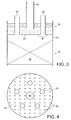
- Figure 3 depicts a liquid distributor 50 combined with the condenser 34 of Figure 1 (or Figure 2).
- the combination comprises an outside enclosure wall 52 and a liquid distributor plate 54 having vapour risers 56 and liquid distribution apertures 58.
- Below the liquid distributor 50 is a packed arrangement 36 of high surface area contact packing.
- the packed arrangement 36 will usually have a support system (not shown) provided underneath and possibly a hold-down system (not shown) provided above.
- Figure 4 shows a plan view of the distributor plate 54 with the vapour risers 56 and the distribution apertures 58.
- Any known alternative type of liquid distribution method (such a trough distributor) can be used in place of the plate and riser type shown.
- Sub-cooled liquid enters the distributor 50 via feed pipe 60 and is distributed substantially uniformly through apertures 58 on to the top end portion of the packed arrangement 36 of the packing material.
- Boil-off vapour is free to enter the condenser 34 from above and from below as the top and bottom ends of the condenser are open to the vapour space.
- the top vapour travels downwards through the vapour risers 56.
- vapour also travels upwards into contact material, being "sucked" there by the condensation occurring in the packing.
- a liquid distributor of the type in Figure 3 could flood due to blockage of some distribution apertures 58 or due to higher than design liquid feed flow. As the condenser is open to the vapour space at both ends, such flooding would only reduce the efficiency of the device rather than stop it working. Excess liquid would overflow the top of the enclosure wall 52 (which ideally should be a lower elevation than the top of the risers 56 so that vapour entry from above is not restricted).
- condenser device can be located at any convenient location in the storage vapour space, i.e. it does not need to be located locally to where the vent line 18 is located.
Landscapes
- Engineering & Computer Science (AREA)
- Mechanical Engineering (AREA)
- General Engineering & Computer Science (AREA)
- Physics & Mathematics (AREA)
- Thermal Sciences (AREA)
- Chemical & Material Sciences (AREA)
- Chemical Kinetics & Catalysis (AREA)
- General Chemical & Material Sciences (AREA)
- Oil, Petroleum & Natural Gas (AREA)
- Health & Medical Sciences (AREA)
- Emergency Medicine (AREA)
- Combustion & Propulsion (AREA)
- Ocean & Marine Engineering (AREA)
- Filling Or Discharging Of Gas Storage Vessels (AREA)
Applications Claiming Priority (1)
| Application Number | Priority Date | Filing Date | Title |
|---|---|---|---|
| GBGB0519886.6A GB0519886D0 (en) | 2005-09-29 | 2005-09-29 | A storage vessel for cryogenic liquid |
Publications (3)
| Publication Number | Publication Date |
|---|---|
| EP1770326A2 true EP1770326A2 (fr) | 2007-04-04 |
| EP1770326A3 EP1770326A3 (fr) | 2009-06-03 |
| EP1770326B1 EP1770326B1 (fr) | 2010-03-24 |
Family
ID=35395008
Family Applications (1)
| Application Number | Title | Priority Date | Filing Date |
|---|---|---|---|
| EP06254948A Not-in-force EP1770326B1 (fr) | 2005-09-29 | 2006-09-25 | Réservoir pour liquide cryogénique |
Country Status (10)
| Country | Link |
|---|---|
| US (1) | US7581405B2 (fr) |
| EP (1) | EP1770326B1 (fr) |
| KR (1) | KR101188520B1 (fr) |
| CN (1) | CN100422625C (fr) |
| AT (1) | ATE462106T1 (fr) |
| DE (1) | DE602006013082D1 (fr) |
| ES (1) | ES2343265T3 (fr) |
| GB (1) | GB0519886D0 (fr) |
| SG (1) | SG131095A1 (fr) |
| TW (1) | TWI343975B (fr) |
Cited By (3)
| Publication number | Priority date | Publication date | Assignee | Title |
|---|---|---|---|---|
| WO2011036579A3 (fr) * | 2009-09-28 | 2013-06-27 | Koninklijke Philips Electronics N.V. | Système et procédé de liquéfaction et de stockage d'un fluide |
| WO2014135258A1 (fr) * | 2013-03-08 | 2014-09-12 | Linde Aktiengesellschaft | Procédé de remplissage d'un réservoir de stockage en milieu gazeux sous pression, en particulier en hydrogène |
| EP2896872A1 (fr) * | 2014-01-21 | 2015-07-22 | Cryolor | Station et procédé de fourniture d'un fluide carburant inflammable cryogénique |
Families Citing this family (20)
| Publication number | Priority date | Publication date | Assignee | Title |
|---|---|---|---|---|
| DE102005028199A1 (de) * | 2005-06-17 | 2006-12-21 | Linde Ag | Speicherbehälter für kyrogene Medien |
| KR100834273B1 (ko) * | 2007-03-20 | 2008-05-30 | 대우조선해양 주식회사 | 멤브레인형 lng 저장탱크, 그 탱크가 설치된lng운반선, 및 lng운반방법 |
| US20120000242A1 (en) * | 2010-04-22 | 2012-01-05 | Baudat Ned P | Method and apparatus for storing liquefied natural gas |
| US9869429B2 (en) | 2010-08-25 | 2018-01-16 | Chart Industries, Inc. | Bulk cryogenic liquid pressurized dispensing system and method |
| US9939109B2 (en) * | 2010-08-25 | 2018-04-10 | Chart Inc. | Bulk liquid cooling and pressurized dispensing system and method |
| US20120102979A1 (en) * | 2010-10-29 | 2012-05-03 | Newman Michael D | Nitrogen fog generator |
| GB2499815B (en) * | 2012-02-29 | 2014-05-28 | Siemens Plc | Over-pressure limiting arrangement for a cryogen vessel |
| NO2932147T3 (fr) * | 2012-12-14 | 2018-03-17 | ||
| EP3559540B1 (fr) | 2016-12-23 | 2022-09-14 | Shell Internationale Research Maatschappij B.V. | Navire de transport de gaz liquéfié et procédé d'utilisation du navire |
| FR3066248B1 (fr) * | 2017-05-12 | 2020-12-11 | Gaztransport Et Technigaz | Procede et systeme de traitement de gaz d'une installation de stockage de gaz pour un navire de transport de gaz |
| JP6834999B2 (ja) * | 2018-01-29 | 2021-02-24 | Jfeエンジニアリング株式会社 | Lngタンクの蒸発ガス抑制装置及び蒸発ガス抑制方法 |
| JP6922769B2 (ja) * | 2018-02-07 | 2021-08-18 | Jfeエンジニアリング株式会社 | 低温液化ガス貯留タンクのbog抑制方法及び装置 |
| KR102732330B1 (ko) * | 2018-05-30 | 2024-11-20 | 가즈트랑스포르 에 떼끄니가즈 | 액화 가스 저장 장치 |
| US11566753B2 (en) * | 2018-12-27 | 2023-01-31 | Chart Inc. | Vapor pressure regulator for cryogenic liquid storage tanks and tanks including the same |
| JP7227837B2 (ja) * | 2019-04-23 | 2023-02-22 | 三菱造船株式会社 | 液化ガス貯留タンク、及び船舶 |
| US11608937B2 (en) | 2020-01-30 | 2023-03-21 | Caterpillar Inc. | Separation and venting cryogenic liquid from vapor on a mobile machine |
| US20220243871A1 (en) * | 2021-01-29 | 2022-08-04 | Cryogenic Fuels Inc. | Tank for storing liquid hydrogen and method of use |
| FR3129454B1 (fr) * | 2021-11-25 | 2024-08-02 | Air Liquide | Réservoir de stockage de gaz liquéfié et procédé de transfert de fluide |
| CN114263845A (zh) * | 2022-01-18 | 2022-04-01 | 中海石油气电集团有限责任公司 | 一种主容器非自支撑低压液氢混凝土储罐 |
| EP4735789A1 (fr) * | 2023-06-27 | 2026-05-06 | L'Air Liquide, Société Anonyme pour l'Etude et l'Exploitation des Procédés Georges Claude | Architecture de chargement de remorques d'hydrogène liquide |
Citations (2)
| Publication number | Priority date | Publication date | Assignee | Title |
|---|---|---|---|---|
| US2059942A (en) | 1934-01-31 | 1936-11-03 | Gen Motors Corp | Refrigerating apparatus |
| US2938360A (en) | 1957-12-23 | 1960-05-31 | Chemical Construction Corp | Anhydrous ammonia storage tank |
Family Cites Families (18)
| Publication number | Priority date | Publication date | Assignee | Title |
|---|---|---|---|---|
| US2784560A (en) | 1954-02-11 | 1957-03-12 | American Messer Corp | Process and apparatus for storing and shipping liquefied gases |
| US2944405A (en) | 1955-10-27 | 1960-07-12 | Union Tank Car Co | Conservation arrangement |
| US3098362A (en) * | 1959-11-04 | 1963-07-23 | Sohda Yoshitoshi | Container vessel for storage and transportation of liquefied natural gases |
| NL123786C (fr) * | 1960-12-23 | 1967-10-16 | ||
| US3191394A (en) * | 1963-03-26 | 1965-06-29 | Union Tank Car Co | Conservation arrangement and method |
| US3453836A (en) * | 1967-07-24 | 1969-07-08 | Mcmullen John J | Liquefied petroleum gas tanker |
| US3780534A (en) | 1969-07-22 | 1973-12-25 | Airco Inc | Liquefaction of natural gas with product used as absorber purge |
| FR2165729B1 (fr) * | 1971-12-27 | 1976-02-13 | Technigaz Fr | |
| SU842329A1 (ru) | 1976-06-14 | 1981-06-30 | Предприятие П/Я Г-4461 | Устройство дл бездренажного хранени КРиОгЕННыХ жидКОСТЕй |
| FR2406782A1 (fr) | 1977-10-20 | 1979-05-18 | Air Liquide | Evaporateur pour melanges cryogeniques |
| US4551981A (en) | 1981-05-20 | 1985-11-12 | The Boc Group, Inc. | Heat exchange methods and apparatus |
| SU1631224A2 (ru) | 1989-03-13 | 1991-02-28 | Войсковая Часть 11284 | Устройство дл хранени криогенных жидкостей |
| JPH0726784B2 (ja) | 1992-09-25 | 1995-03-29 | 岩谷産業株式会社 | 簡易液体窒素製造装置 |
| US5579646A (en) | 1995-05-24 | 1996-12-03 | The Boc Group, Inc. | Cryogen delivery apparatus |
| US5590535A (en) | 1995-11-13 | 1997-01-07 | Chicago Bridge & Iron Technical Services Company | Process and apparatus for conditioning cryogenic fuel to establish a selected equilibrium pressure |
| WO2000079179A1 (fr) | 1999-06-23 | 2000-12-28 | Chicago Bridge & Iron Company | Systeme et appareil de condensation de vapeur evaporee provenant d'un conteneur de gaz naturel liquefie |
| NO312484B1 (no) * | 2000-07-26 | 2002-05-13 | Venturie As | Gasskondensator |
| CN1894537B (zh) * | 2003-12-15 | 2010-06-09 | Bp北美公司 | 液化天然气的汽化系统和方法 |
-
2005
- 2005-09-29 GB GBGB0519886.6A patent/GB0519886D0/en not_active Ceased
-
2006
- 2006-09-06 US US11/516,220 patent/US7581405B2/en not_active Expired - Fee Related
- 2006-09-25 EP EP06254948A patent/EP1770326B1/fr not_active Not-in-force
- 2006-09-25 AT AT06254948T patent/ATE462106T1/de not_active IP Right Cessation
- 2006-09-25 ES ES06254948T patent/ES2343265T3/es active Active
- 2006-09-25 DE DE602006013082T patent/DE602006013082D1/de active Active
- 2006-09-26 KR KR1020060093450A patent/KR101188520B1/ko not_active Expired - Fee Related
- 2006-09-27 SG SG200606731-8A patent/SG131095A1/en unknown
- 2006-09-27 TW TW095135867A patent/TWI343975B/zh not_active IP Right Cessation
- 2006-09-29 CN CNB2006101413312A patent/CN100422625C/zh not_active Expired - Fee Related
Patent Citations (2)
| Publication number | Priority date | Publication date | Assignee | Title |
|---|---|---|---|---|
| US2059942A (en) | 1934-01-31 | 1936-11-03 | Gen Motors Corp | Refrigerating apparatus |
| US2938360A (en) | 1957-12-23 | 1960-05-31 | Chemical Construction Corp | Anhydrous ammonia storage tank |
Cited By (5)
| Publication number | Priority date | Publication date | Assignee | Title |
|---|---|---|---|---|
| WO2011036579A3 (fr) * | 2009-09-28 | 2013-06-27 | Koninklijke Philips Electronics N.V. | Système et procédé de liquéfaction et de stockage d'un fluide |
| WO2014135258A1 (fr) * | 2013-03-08 | 2014-09-12 | Linde Aktiengesellschaft | Procédé de remplissage d'un réservoir de stockage en milieu gazeux sous pression, en particulier en hydrogène |
| US9759382B2 (en) | 2013-03-08 | 2017-09-12 | Linde Aktiengesellschaft | Method for filling up a storage tank with a gaseous pressurized medium, in particular hydrogen |
| EP2896872A1 (fr) * | 2014-01-21 | 2015-07-22 | Cryolor | Station et procédé de fourniture d'un fluide carburant inflammable cryogénique |
| FR3016676A1 (fr) * | 2014-01-21 | 2015-07-24 | Cryolor | Station et procede de fourniture d'un fluide carburant inflammable |
Also Published As
| Publication number | Publication date |
|---|---|
| KR20070036679A (ko) | 2007-04-03 |
| CN1940376A (zh) | 2007-04-04 |
| TWI343975B (en) | 2011-06-21 |
| GB0519886D0 (en) | 2005-11-09 |
| TW200714833A (en) | 2007-04-16 |
| CN100422625C (zh) | 2008-10-01 |
| US20070068177A1 (en) | 2007-03-29 |
| SG131095A1 (en) | 2007-04-26 |
| EP1770326A3 (fr) | 2009-06-03 |
| EP1770326B1 (fr) | 2010-03-24 |
| DE602006013082D1 (de) | 2010-05-06 |
| ATE462106T1 (de) | 2010-04-15 |
| US7581405B2 (en) | 2009-09-01 |
| ES2343265T3 (es) | 2010-07-27 |
| KR101188520B1 (ko) | 2012-10-05 |
Similar Documents
| Publication | Publication Date | Title |
|---|---|---|
| EP1770326B1 (fr) | Réservoir pour liquide cryogénique | |
| CA2466094C (fr) | Procede d'absorption de vapeurs et de gaz de reservoirs sous pression | |
| JP4526188B2 (ja) | コンテナからの圧縮液化天然ガスの排出方法 | |
| JP6684789B2 (ja) | 液化ガスを冷却するための装置および方法 | |
| AU2012364280B2 (en) | Methods for storing cryogenic fluids in storage vessels | |
| NO135880B (fr) | ||
| CN107636380A (zh) | 用于冷却液化气体的方法 | |
| CN113800140A (zh) | 用于管理地下低温液体储罐中的压力的系统和方法 | |
| US11441840B2 (en) | Process and plant for the production of argon by cryogenic distillation of air | |
| JP2010511127A (ja) | Lngの再ガス化 | |
| GB1566232A (en) | Liquefied gas tank and method of filling | |
| US7293417B2 (en) | Methods and apparatus for processing, transporting and/or storing cryogenic fluids | |
| RU2399508C2 (ru) | Резервуар для хранения криогенной жидкости | |
| JP2000142894A (ja) | 酸素含有混合物からなる液体を貯蔵及び分配する方法及び装置 | |
| US20230003345A1 (en) | System and Method for Transfering Liquid Argon to Bulk Transport Tanks | |
| CN102016467A (zh) | 用于通过低温蒸馏分离空气的方法和装置 | |
| JPH11153296A (ja) | 低温液化ガス貯蔵設備 | |
| KR20150138994A (ko) | 액화가스 처리 시스템 |
Legal Events
| Date | Code | Title | Description |
|---|---|---|---|
| PUAI | Public reference made under article 153(3) epc to a published international application that has entered the european phase |
Free format text: ORIGINAL CODE: 0009012 |
|
| AK | Designated contracting states |
Kind code of ref document: A2 Designated state(s): AT BE BG CH CY CZ DE DK EE ES FI FR GB GR HU IE IS IT LI LT LU LV MC NL PL PT RO SE SI SK TR |
|
| AX | Request for extension of the european patent |
Extension state: AL BA HR MK YU |
|
| PUAL | Search report despatched |
Free format text: ORIGINAL CODE: 0009013 |
|
| AK | Designated contracting states |
Kind code of ref document: A3 Designated state(s): AT BE BG CH CY CZ DE DK EE ES FI FR GB GR HU IE IS IT LI LT LU LV MC NL PL PT RO SE SI SK TR |
|
| AX | Request for extension of the european patent |
Extension state: AL BA HR MK RS |
|
| RIC1 | Information provided on ipc code assigned before grant |
Ipc: F17C 1/00 20060101AFI20070124BHEP Ipc: F17C 13/12 20060101ALI20090428BHEP |
|
| 17P | Request for examination filed |
Effective date: 20090701 |
|
| RIC1 | Information provided on ipc code assigned before grant |
Ipc: F17C 1/00 20060101AFI20090720BHEP Ipc: F17C 13/12 20060101ALI20090720BHEP |
|
| GRAP | Despatch of communication of intention to grant a patent |
Free format text: ORIGINAL CODE: EPIDOSNIGR1 |
|
| GRAS | Grant fee paid |
Free format text: ORIGINAL CODE: EPIDOSNIGR3 |
|
| AKX | Designation fees paid |
Designated state(s): AT BE BG CH CY CZ DE DK EE ES FI FR GB GR HU IE IS IT LI LT LU LV MC NL PL PT RO SE SI SK TR |
|
| GRAA | (expected) grant |
Free format text: ORIGINAL CODE: 0009210 |
|
| AK | Designated contracting states |
Kind code of ref document: B1 Designated state(s): AT BE BG CH CY CZ DE DK EE ES FI FR GB GR HU IE IS IT LI LT LU LV MC NL PL PT RO SE SI SK TR |
|
| REG | Reference to a national code |
Ref country code: GB Ref legal event code: FG4D |
|
| REG | Reference to a national code |
Ref country code: CH Ref legal event code: EP |
|
| REG | Reference to a national code |
Ref country code: IE Ref legal event code: FG4D |
|
| REF | Corresponds to: |
Ref document number: 602006013082 Country of ref document: DE Date of ref document: 20100506 Kind code of ref document: P |
|
| REG | Reference to a national code |
Ref country code: NL Ref legal event code: T3 |
|
| REG | Reference to a national code |
Ref country code: ES Ref legal event code: FG2A Ref document number: 2343265 Country of ref document: ES Kind code of ref document: T3 |
|
| PG25 | Lapsed in a contracting state [announced via postgrant information from national office to epo] |
Ref country code: LT Free format text: LAPSE BECAUSE OF FAILURE TO SUBMIT A TRANSLATION OF THE DESCRIPTION OR TO PAY THE FEE WITHIN THE PRESCRIBED TIME-LIMIT Effective date: 20100324 |
|
| LTIE | Lt: invalidation of european patent or patent extension |
Effective date: 20100324 |
|
| PG25 | Lapsed in a contracting state [announced via postgrant information from national office to epo] |
Ref country code: SI Free format text: LAPSE BECAUSE OF FAILURE TO SUBMIT A TRANSLATION OF THE DESCRIPTION OR TO PAY THE FEE WITHIN THE PRESCRIBED TIME-LIMIT Effective date: 20100324 Ref country code: PL Free format text: LAPSE BECAUSE OF FAILURE TO SUBMIT A TRANSLATION OF THE DESCRIPTION OR TO PAY THE FEE WITHIN THE PRESCRIBED TIME-LIMIT Effective date: 20100324 Ref country code: LV Free format text: LAPSE BECAUSE OF FAILURE TO SUBMIT A TRANSLATION OF THE DESCRIPTION OR TO PAY THE FEE WITHIN THE PRESCRIBED TIME-LIMIT Effective date: 20100324 Ref country code: FI Free format text: LAPSE BECAUSE OF FAILURE TO SUBMIT A TRANSLATION OF THE DESCRIPTION OR TO PAY THE FEE WITHIN THE PRESCRIBED TIME-LIMIT Effective date: 20100324 Ref country code: AT Free format text: LAPSE BECAUSE OF FAILURE TO SUBMIT A TRANSLATION OF THE DESCRIPTION OR TO PAY THE FEE WITHIN THE PRESCRIBED TIME-LIMIT Effective date: 20100324 |
|
| PG25 | Lapsed in a contracting state [announced via postgrant information from national office to epo] |
Ref country code: EE Free format text: LAPSE BECAUSE OF FAILURE TO SUBMIT A TRANSLATION OF THE DESCRIPTION OR TO PAY THE FEE WITHIN THE PRESCRIBED TIME-LIMIT Effective date: 20100324 Ref country code: SE Free format text: LAPSE BECAUSE OF FAILURE TO SUBMIT A TRANSLATION OF THE DESCRIPTION OR TO PAY THE FEE WITHIN THE PRESCRIBED TIME-LIMIT Effective date: 20100324 Ref country code: RO Free format text: LAPSE BECAUSE OF FAILURE TO SUBMIT A TRANSLATION OF THE DESCRIPTION OR TO PAY THE FEE WITHIN THE PRESCRIBED TIME-LIMIT Effective date: 20100324 Ref country code: GR Free format text: LAPSE BECAUSE OF FAILURE TO SUBMIT A TRANSLATION OF THE DESCRIPTION OR TO PAY THE FEE WITHIN THE PRESCRIBED TIME-LIMIT Effective date: 20100625 |
|
| PG25 | Lapsed in a contracting state [announced via postgrant information from national office to epo] |
Ref country code: BG Free format text: LAPSE BECAUSE OF FAILURE TO SUBMIT A TRANSLATION OF THE DESCRIPTION OR TO PAY THE FEE WITHIN THE PRESCRIBED TIME-LIMIT Effective date: 20100624 Ref country code: CZ Free format text: LAPSE BECAUSE OF FAILURE TO SUBMIT A TRANSLATION OF THE DESCRIPTION OR TO PAY THE FEE WITHIN THE PRESCRIBED TIME-LIMIT Effective date: 20100324 Ref country code: SK Free format text: LAPSE BECAUSE OF FAILURE TO SUBMIT A TRANSLATION OF THE DESCRIPTION OR TO PAY THE FEE WITHIN THE PRESCRIBED TIME-LIMIT Effective date: 20100324 Ref country code: IS Free format text: LAPSE BECAUSE OF FAILURE TO SUBMIT A TRANSLATION OF THE DESCRIPTION OR TO PAY THE FEE WITHIN THE PRESCRIBED TIME-LIMIT Effective date: 20100724 |
|
| PLBE | No opposition filed within time limit |
Free format text: ORIGINAL CODE: 0009261 |
|
| STAA | Information on the status of an ep patent application or granted ep patent |
Free format text: STATUS: NO OPPOSITION FILED WITHIN TIME LIMIT |
|
| PG25 | Lapsed in a contracting state [announced via postgrant information from national office to epo] |
Ref country code: DK Free format text: LAPSE BECAUSE OF FAILURE TO SUBMIT A TRANSLATION OF THE DESCRIPTION OR TO PAY THE FEE WITHIN THE PRESCRIBED TIME-LIMIT Effective date: 20100324 Ref country code: PT Free format text: LAPSE BECAUSE OF FAILURE TO SUBMIT A TRANSLATION OF THE DESCRIPTION OR TO PAY THE FEE WITHIN THE PRESCRIBED TIME-LIMIT Effective date: 20100726 |
|
| 26N | No opposition filed |
Effective date: 20101228 |
|
| PG25 | Lapsed in a contracting state [announced via postgrant information from national office to epo] |
Ref country code: MC Free format text: LAPSE BECAUSE OF NON-PAYMENT OF DUE FEES Effective date: 20100930 |
|
| REG | Reference to a national code |
Ref country code: CH Ref legal event code: PL |
|
| PG25 | Lapsed in a contracting state [announced via postgrant information from national office to epo] |
Ref country code: IE Free format text: LAPSE BECAUSE OF NON-PAYMENT OF DUE FEES Effective date: 20100925 Ref country code: CH Free format text: LAPSE BECAUSE OF NON-PAYMENT OF DUE FEES Effective date: 20100930 Ref country code: LI Free format text: LAPSE BECAUSE OF NON-PAYMENT OF DUE FEES Effective date: 20100930 |
|
| PG25 | Lapsed in a contracting state [announced via postgrant information from national office to epo] |
Ref country code: CY Free format text: LAPSE BECAUSE OF FAILURE TO SUBMIT A TRANSLATION OF THE DESCRIPTION OR TO PAY THE FEE WITHIN THE PRESCRIBED TIME-LIMIT Effective date: 20100324 |
|
| PG25 | Lapsed in a contracting state [announced via postgrant information from national office to epo] |
Ref country code: HU Free format text: LAPSE BECAUSE OF FAILURE TO SUBMIT A TRANSLATION OF THE DESCRIPTION OR TO PAY THE FEE WITHIN THE PRESCRIBED TIME-LIMIT Effective date: 20100925 Ref country code: LU Free format text: LAPSE BECAUSE OF NON-PAYMENT OF DUE FEES Effective date: 20100925 |
|
| PG25 | Lapsed in a contracting state [announced via postgrant information from national office to epo] |
Ref country code: TR Free format text: LAPSE BECAUSE OF FAILURE TO SUBMIT A TRANSLATION OF THE DESCRIPTION OR TO PAY THE FEE WITHIN THE PRESCRIBED TIME-LIMIT Effective date: 20100324 |
|
| PGFP | Annual fee paid to national office [announced via postgrant information from national office to epo] |
Ref country code: NL Payment date: 20130912 Year of fee payment: 8 Ref country code: ES Payment date: 20130917 Year of fee payment: 8 |
|
| PGFP | Annual fee paid to national office [announced via postgrant information from national office to epo] |
Ref country code: GB Payment date: 20130827 Year of fee payment: 8 |
|
| PGFP | Annual fee paid to national office [announced via postgrant information from national office to epo] |
Ref country code: IT Payment date: 20130919 Year of fee payment: 8 |
|
| PGFP | Annual fee paid to national office [announced via postgrant information from national office to epo] |
Ref country code: BE Payment date: 20131002 Year of fee payment: 8 |
|
| PGFP | Annual fee paid to national office [announced via postgrant information from national office to epo] |
Ref country code: FR Payment date: 20140825 Year of fee payment: 9 |
|
| PGFP | Annual fee paid to national office [announced via postgrant information from national office to epo] |
Ref country code: DE Payment date: 20140930 Year of fee payment: 9 |
|
| GBPC | Gb: european patent ceased through non-payment of renewal fee |
Effective date: 20140925 |
|
| PG25 | Lapsed in a contracting state [announced via postgrant information from national office to epo] |
Ref country code: BE Free format text: LAPSE BECAUSE OF NON-PAYMENT OF DUE FEES Effective date: 20140930 Ref country code: NL Free format text: LAPSE BECAUSE OF NON-PAYMENT OF DUE FEES Effective date: 20150401 |
|
| PG25 | Lapsed in a contracting state [announced via postgrant information from national office to epo] |
Ref country code: GB Free format text: LAPSE BECAUSE OF NON-PAYMENT OF DUE FEES Effective date: 20140925 |
|
| PG25 | Lapsed in a contracting state [announced via postgrant information from national office to epo] |
Ref country code: IT Free format text: LAPSE BECAUSE OF NON-PAYMENT OF DUE FEES Effective date: 20140925 |
|
| REG | Reference to a national code |
Ref country code: ES Ref legal event code: FD2A Effective date: 20151026 |
|
| PG25 | Lapsed in a contracting state [announced via postgrant information from national office to epo] |
Ref country code: ES Free format text: LAPSE BECAUSE OF NON-PAYMENT OF DUE FEES Effective date: 20140926 |
|
| REG | Reference to a national code |
Ref country code: DE Ref legal event code: R119 Ref document number: 602006013082 Country of ref document: DE |
|
| REG | Reference to a national code |
Ref country code: FR Ref legal event code: ST Effective date: 20160531 |
|
| PG25 | Lapsed in a contracting state [announced via postgrant information from national office to epo] |
Ref country code: DE Free format text: LAPSE BECAUSE OF NON-PAYMENT OF DUE FEES Effective date: 20160401 |
|
| PG25 | Lapsed in a contracting state [announced via postgrant information from national office to epo] |
Ref country code: FR Free format text: LAPSE BECAUSE OF NON-PAYMENT OF DUE FEES Effective date: 20150930 |