EP1770480A2 - Procédé et mesure de signaux tactiles et unité tactile - Google Patents
Procédé et mesure de signaux tactiles et unité tactile Download PDFInfo
- Publication number
- EP1770480A2 EP1770480A2 EP06450115A EP06450115A EP1770480A2 EP 1770480 A2 EP1770480 A2 EP 1770480A2 EP 06450115 A EP06450115 A EP 06450115A EP 06450115 A EP06450115 A EP 06450115A EP 1770480 A2 EP1770480 A2 EP 1770480A2
- Authority
- EP
- European Patent Office
- Prior art keywords
- touch
- current
- resistance
- voltage
- measured
- Prior art date
- Legal status (The legal status is an assumption and is not a legal conclusion. Google has not performed a legal analysis and makes no representation as to the accuracy of the status listed.)
- Withdrawn
Links
Images


Classifications
-
- G—PHYSICS
- G06—COMPUTING OR CALCULATING; COUNTING
- G06F—ELECTRIC DIGITAL DATA PROCESSING
- G06F3/00—Input arrangements for transferring data to be processed into a form capable of being handled by the computer; Output arrangements for transferring data from processing unit to output unit, e.g. interface arrangements
- G06F3/01—Input arrangements or combined input and output arrangements for interaction between user and computer
- G06F3/03—Arrangements for converting the position or the displacement of a member into a coded form
- G06F3/041—Digitisers, e.g. for touch screens or touch pads, characterised by the transducing means
- G06F3/045—Digitisers, e.g. for touch screens or touch pads, characterised by the transducing means using resistive elements, e.g. a single continuous surface or two parallel surfaces put in contact
-
- G—PHYSICS
- G06—COMPUTING OR CALCULATING; COUNTING
- G06F—ELECTRIC DIGITAL DATA PROCESSING
- G06F2203/00—Indexing scheme relating to G06F3/00 - G06F3/048
- G06F2203/041—Indexing scheme relating to G06F3/041 - G06F3/045
- G06F2203/04104—Multi-touch detection in digitiser, i.e. details about the simultaneous detection of a plurality of touching locations, e.g. multiple fingers or pen and finger
Definitions
- the invention relates to a method according to the preamble of claim 1 and a touch unit according to the preamble of claim 5.
- the aim of the invention is to be able to determine the presence of a double touch in touch units exactly and clearly with little circuit complexity.
- the required circuit engineering and structural design should be as simple and inexpensive as possible and at the same time reliable. What is essential, however, is the rapid and clear recognition of the presence of a double touch.
- a touch unit according to the invention is characterized by the features cited in the characterizing part of claim 5.
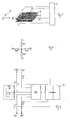
- FIG. 1 shows schematically two spaced-apart resistance foils of a touch unit with an evaluation unit
- FIG. 2 shows an equivalent circuit diagram
- FIG. 3 shows a schematic block diagram for determining the presence of a touch
- FIG. 4 shows schematically the program sequence of an evaluation method relating to FIG
- Fig. 5 is an equivalent circuit diagram for a double touch
- Fig. 6 is a simplified equivalent circuit diagram
- Fig. 7 shows schematically a touch unit according to the invention or an arrangement for determining the presence of a double touch
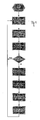
- Fig 8 schematically shows a flowchart relating to the procedure according to the invention.
- Fig. 1 shows schematically a basic configuration of a touch unit.
- a touch unit comprises two, in particular transparent, resistance foils 1, 2 which are arranged at a distance from one another. In their opposite end regions, the resistance foils 1, 2 are contacted in order to be able to apply a measuring voltage to the foils 1, 2.
- the one resistance foil 1 has contacts A and B which are intended to specify the X direction; the other resistance foil 2 has the contacts C and D which define the Y direction.
- the connections are led to a control or evaluation unit 3, with which predetermined voltage values are applied to the terminals A and B or C and D at the respectively predetermined times.
- the control or evaluation unit 3 measures the voltages occurring between the non-voltage-loaded terminals by means of a voltage-current measuring unit at given times.
- Fig. 4 describes the hitherto conventional measuring method for detecting the presence and the position of a touch.
- a predetermined voltage is applied to the connection points A and B of the measuring film 1 more than two hundred times per second.
- a voltage is applied to the connection point D of the other measuring film 2 in order to bring this resistance film 2 to a defined voltage output level (0 V).
- the same voltage is applied again only at the connection points A and B and the occurring voltage is measured at the connection point D.
- connection point D If it is found that the voltage at connection point D is less than a predetermined voltage value or does not exceed the voltage previously measured at this connection point, this means that there is no touch. If the voltage measured at connection point D is greater than a predetermined or previously measured voltage value, this is evaluated as the presence of a touch, and the position of the touch is subsequently calculated in a corresponding manner. For this purpose, a predetermined measuring voltage is applied between the connection points A and B and the occurring voltage between the connection points C and D is measured. Due to the height of the measured voltage value, a statement about the X position of the touch can be made. In the following, a predetermined measuring voltage is applied to the connection points C and D and the voltage occurring between the Connection points A and B measured. From this, the position of the touch in the Y direction can be determined.
- the resistance is always constant, i. is e.g. In the X direction, the measuring voltage is applied, so the resistance through which the measuring current must flow is always Rx. But if, for example, triggered a double touch in the X-axis, as shown above, so forms over Rx2 a parallel circuit of two resistors, which are also about the same size.
- Rx2 is the resistance on the "X-foil” while the resistor in parallel is formed on the "Y-foil”. This parallel resistance Ra + Ra is determined by the two pressure points and also determines the current.
- Rx Rx1 + (Rx2 / 2) + Rx3 for a double touch, i. the resistance becomes smaller and thus the current flowing between the terminals A, B becomes larger. (Fig. 6)
- the current is additionally measured and compared with a previously or subsequently measured current value. If the difference is greater than a predetermined limit, then there is a double touch and can be signaled. Since the current changes can sometimes be very small, the closer to each other, the touches of the Double Touch are triggered, the current measurement is performed with their own ADC channels, as shown in Fig. 7.
- Fig. 8 shows schematically a flow chart concerning the procedure according to the invention. This procedure is divided into one, in particular in advance determining if there is any touch at all, followed by checking if there is a double touch followed by measuring the position of a touch, if it has been determined that there is only one touch. These checks take place alternately for the two resistance foils 1, 2, in order to be able to make appropriate determinations for the X-direction or the Y-direction. In principle, the check according to the invention could also be carried out only for a resistance foil or one of the two directions; this is especially possible if it is assumed that a double touch, in which the two touches occupy the same X position or the same Y position, is excluded or tolerated.
- the order in which the check or measurement of the resistance foils is made is arbitrary. Furthermore, it is also possible in principle to measure a touch and only then determine whether a double touch is present and then discard the value obtained. The determination of the presence of a double touch before measuring the voltages and current flows occurring on the resistance foils is preferable for reasons of simplicity of the circuit design.
- Step 10 The start of a measuring cycle takes place.
- Step 11 A predetermined voltage UX is applied to the resistance foil 1 at the connection points A, B, and the current IX flowing through the measuring foil 1 is measured. The value of this current is used for subsequent measurements and stored as set current value IXS.
- Step 12 A predetermined voltage UY is applied to the connection locations C, D of the resistance foil 2 and the current flowing through the resistance foil 2 is measured. This actual current value IY is possibly stored as a new setpoint current value IYS comparable to step 16.
- the predetermined voltages UX and UY are the same in magnitude as the voltages used to detect whether a touch is present or to check for double touch. However, these voltages do not have to correspond to the measuring voltages with which the position of a single touch is determined.
- Step 13 To determine whether there is any touch, the voltage UX is applied to the connection points A, B. Furthermore, a voltage is applied to the connection point D.
- Step 14 The current IX flowing in the resistor foil 1 between the terminals A and B is measured.
- Step 15 The initially measured target current value IXS is compared with the current value IX measured in step 14.
- step 21 If the difference between the target current value IXS and the current value IX measured in step 14 exceeds a desired minimum value LimPress, this is evaluated as the presence of a touch and fed to a touch test unit (see step 21). If the test criterion corresponding to step 15 is not met, the measured current IX is stored as a new target current value IXS according to section 16, at most at the same voltage at the connection points A and B resulting from changes in resistance, for example due to heating of the resistance foils, consider different current flows can. Step 17: As shown in step 13, a voltage is applied to terminals B, C and D. Step 18: There is a measurement of the current IY, which flows between the connection points B and C.
- Step 19 A comparison of the nominal current value IYS with the current IY measured in step 18 or the determination as to whether the difference formed is greater than a predetermined current value LimPress. If this difference is greater, this is regarded as the presence of a touch and the fulfillment of this criterion is considered in step 21.
- step 20 is carried out: the measured current value IY is stored as a new setpoint current value IYS and continued again with step 13. This means that there is no touch; both the inspection of the resistance foil 1 and a check of the resistance foil 2, i. A check of the X-position or Y-position of a touch gave negative results.
- Step 21 Here, the evaluation of the signals generated in steps 15 and 19 takes place.
- Step 22 The test voltage UX is applied to the terminals A and B of the resistor foil 1.
- Step 23 The actual current IX occurring when the measuring voltage UX is applied to the resistance foil 1 is measured.
- Step 24 A comparison is made of the occurring actual current IX with the stored nominal current value IXS. If a positive difference results, which is greater than a predetermined threshold LimDT, then this becomes Step 25 counted as having a double touch.
- Step 26 The voltage at terminals C and D is measured and these voltage values are used to determine the X position of the present touch.
- Step 27 As a further step, comparable to step 22, the measuring voltage UY is applied to the connection points C and D. It is noted that the measuring voltages UX and UY need not be the same size.
- Step 28 The measurement of the current IY flowing through the resistor foil 2 between the connection points C and D takes place.
- Step 29 A comparison is made of this flowing current IY with the last stored nominal current value IYS or the determination as to whether there is a positive difference that exceeds a predetermined threshold value LimDT. If appropriate, the presence of a double touch is assumed in step 30. If the threshold is not exceeded, then follows Step 31: In this step, the voltage occurring at the connection points A and B is measured and, similar to the step 26, the Y position of the determined touch is determined from this measured value.
- the measuring method can be interrupted and the method is restarted with step 13, or the coordinate measurement can be continued.
- step 13 takes place after step 31.
- the inputs of the voltage current measuring unit 7 are formed by a six-channel ADC and are connected between the resistors RS and the connection points B and D of the respective resistance foil 1 or 2.
- the control unit or measuring and control unit the corresponding measuring devices or units for voltage generation and comparators are integrated. This unit can be realized in hardware or by appropriate software and hardware devices controlled by it.
Landscapes
- Engineering & Computer Science (AREA)
- General Engineering & Computer Science (AREA)
- Theoretical Computer Science (AREA)
- Human Computer Interaction (AREA)
- Physics & Mathematics (AREA)
- General Physics & Mathematics (AREA)
- Measurement Of Resistance Or Impedance (AREA)
- User Interface Of Digital Computer (AREA)
- Measurement Of Length, Angles, Or The Like Using Electric Or Magnetic Means (AREA)
Applications Claiming Priority (1)
| Application Number | Priority Date | Filing Date | Title |
|---|---|---|---|
| AT0141305A AT502349B1 (de) | 2005-08-29 | 2005-08-29 | Verfahren zur auswertung von touch-signalen und touch-einheit |
Publications (2)
| Publication Number | Publication Date |
|---|---|
| EP1770480A2 true EP1770480A2 (fr) | 2007-04-04 |
| EP1770480A3 EP1770480A3 (fr) | 2008-06-04 |
Family
ID=37775156
Family Applications (1)
| Application Number | Title | Priority Date | Filing Date |
|---|---|---|---|
| EP06450115A Withdrawn EP1770480A3 (fr) | 2005-08-29 | 2006-08-23 | Procédé et évaluation des signaux tactiles et panneau tactile |
Country Status (3)
| Country | Link |
|---|---|
| US (1) | US7633300B2 (fr) |
| EP (1) | EP1770480A3 (fr) |
| AT (1) | AT502349B1 (fr) |
Cited By (2)
| Publication number | Priority date | Publication date | Assignee | Title |
|---|---|---|---|---|
| EP2799966A1 (fr) | 2013-05-02 | 2014-11-05 | Siemens Aktiengesellschaft | Dispositif d'entrée, unité de contrôle et procédé de détermination de position |
| EP2818990A1 (fr) * | 2010-07-22 | 2014-12-31 | Fujitsu Component Limited | Panneau à écran tactile |
Families Citing this family (22)
| Publication number | Priority date | Publication date | Assignee | Title |
|---|---|---|---|---|
| US9778794B2 (en) | 2001-11-02 | 2017-10-03 | Neonode Inc. | Light-based touch screen |
| US8674966B2 (en) | 2001-11-02 | 2014-03-18 | Neonode Inc. | ASIC controller for light-based touch screen |
| US9052777B2 (en) | 2001-11-02 | 2015-06-09 | Neonode Inc. | Optical elements with alternating reflective lens facets |
| US8339379B2 (en) | 2004-04-29 | 2012-12-25 | Neonode Inc. | Light-based touch screen |
| US8416217B1 (en) | 2002-11-04 | 2013-04-09 | Neonode Inc. | Light-based finger gesture user interface |
| TWI353546B (en) * | 2007-12-19 | 2011-12-01 | Asustek Comp Inc | Touch panel |
| US20090322699A1 (en) * | 2008-06-25 | 2009-12-31 | Sony Ericsson Mobile Communications Ab | Multiple input detection for resistive touch panel |
| US20090322700A1 (en) * | 2008-06-30 | 2009-12-31 | Tyco Electronics Corporation | Method and apparatus for detecting two simultaneous touches and gestures on a resistive touchscreen |
| US20090322701A1 (en) * | 2008-06-30 | 2009-12-31 | Tyco Electronics Corporation | Method and apparatus for detecting two simultaneous touches and gestures on a resistive touchscreen |
| US8775023B2 (en) | 2009-02-15 | 2014-07-08 | Neanode Inc. | Light-based touch controls on a steering wheel and dashboard |
| US8345019B2 (en) * | 2009-02-20 | 2013-01-01 | Elo Touch Solutions, Inc. | Method and apparatus for two-finger touch coordinate recognition and rotation gesture recognition |
| GB2468870B (en) * | 2009-03-25 | 2016-08-03 | Peratech Holdco Ltd | Sensor |
| US8416215B2 (en) | 2010-02-07 | 2013-04-09 | Itay Sherman | Implementation of multi-touch gestures using a resistive touch display |
| US20130027343A1 (en) | 2011-07-29 | 2013-01-31 | Analog Devices, Inc. | Position determination techniques in resistive touch screen applications |
| US9152287B2 (en) | 2010-08-05 | 2015-10-06 | Analog Devices, Inc. | System and method for dual-touch gesture classification in resistive touch screens |
| JP2012088762A (ja) | 2010-10-15 | 2012-05-10 | Touch Panel Systems Kk | タッチパネル入力装置およびジェスチャ検出方法 |
| US9092093B2 (en) | 2012-11-27 | 2015-07-28 | Neonode Inc. | Steering wheel user interface |
| US12032817B2 (en) | 2012-11-27 | 2024-07-09 | Neonode Inc. | Vehicle user interface |
| KR102483721B1 (ko) | 2016-03-02 | 2023-01-02 | 삼성전자주식회사 | 전자 장치 및 그의 동작 방법 |
| WO2020112585A1 (fr) | 2018-11-28 | 2020-06-04 | Neonode Inc. | Capteur d'interface utilisateur d'automobiliste |
| US10990236B2 (en) | 2019-02-07 | 2021-04-27 | 1004335 Ontario Inc. | Methods for two-touch detection with resistive touch sensor and related apparatuses and systems |
| CN116420125A (zh) | 2020-09-30 | 2023-07-11 | 内奥诺德公司 | 光学触摸传感器 |
Citations (2)
| Publication number | Priority date | Publication date | Assignee | Title |
|---|---|---|---|---|
| US20030063073A1 (en) | 2001-10-03 | 2003-04-03 | Geaghan Bernard O. | Touch panel system and method for distinguishing multiple touch inputs |
| US20040090431A1 (en) | 2002-11-13 | 2004-05-13 | Lg.Philips Lcd Co., Ltd. | Touch panel apparatus and method for controlling the same |
Family Cites Families (9)
| Publication number | Priority date | Publication date | Assignee | Title |
|---|---|---|---|---|
| JPS6484325A (en) * | 1987-09-28 | 1989-03-29 | Oki Electric Ind Co Ltd | Multiplex input detecting system in pressure sensitive type input device |
| JPH01269120A (ja) * | 1988-04-21 | 1989-10-26 | Omron Tateisi Electron Co | タッチパネル入力装置 |
| US6255604B1 (en) * | 1995-05-31 | 2001-07-03 | Canon Kabushiki Kaisha | Coordinate detecting device for outputting coordinate data when two points are simultaneously depressed, method therefor and computer control device |
| JP3237629B2 (ja) * | 1998-10-27 | 2001-12-10 | ぺんてる株式会社 | 直接触式タッチパネル装置 |
| EP1399876B1 (fr) * | 2001-06-26 | 2014-11-19 | Casio Computer Co., Ltd. | Appareil d'acquisition d'images |
| KR100469358B1 (ko) * | 2002-12-23 | 2005-02-02 | 엘지.필립스 엘시디 주식회사 | 터치 패널의 구동 방법 |
| JP2004295281A (ja) * | 2003-03-26 | 2004-10-21 | Aiphone Co Ltd | アナログ抵抗膜式タッチパネルの異常入力検出装置 |
| KR100628265B1 (ko) * | 2003-11-24 | 2006-09-27 | 엘지.필립스 엘시디 주식회사 | 저항막 방식의 터치 패널 |
| US6856259B1 (en) * | 2004-02-06 | 2005-02-15 | Elo Touchsystems, Inc. | Touch sensor system to detect multiple touch events |
-
2005
- 2005-08-29 AT AT0141305A patent/AT502349B1/de not_active IP Right Cessation
-
2006
- 2006-08-23 EP EP06450115A patent/EP1770480A3/fr not_active Withdrawn
- 2006-08-29 US US11/512,748 patent/US7633300B2/en not_active Expired - Fee Related
Patent Citations (3)
| Publication number | Priority date | Publication date | Assignee | Title |
|---|---|---|---|---|
| US20030063073A1 (en) | 2001-10-03 | 2003-04-03 | Geaghan Bernard O. | Touch panel system and method for distinguishing multiple touch inputs |
| WO2003030091A1 (fr) | 2001-10-03 | 2003-04-10 | 3M Innovative Properties Company | Systeme de panneau tactile et procede permettant de distinguer des touches de saisie tactiles multiples |
| US20040090431A1 (en) | 2002-11-13 | 2004-05-13 | Lg.Philips Lcd Co., Ltd. | Touch panel apparatus and method for controlling the same |
Cited By (4)
| Publication number | Priority date | Publication date | Assignee | Title |
|---|---|---|---|---|
| EP2818990A1 (fr) * | 2010-07-22 | 2014-12-31 | Fujitsu Component Limited | Panneau à écran tactile |
| US9235311B2 (en) | 2010-07-22 | 2016-01-12 | Fujitsu Component Limited | Method of initializing touchscreen panel |
| US10318063B2 (en) | 2010-07-22 | 2019-06-11 | Fujitsu Component Limited | Touchscreen panel, and method of initializing touchscreen panel |
| EP2799966A1 (fr) | 2013-05-02 | 2014-11-05 | Siemens Aktiengesellschaft | Dispositif d'entrée, unité de contrôle et procédé de détermination de position |
Also Published As
| Publication number | Publication date |
|---|---|
| AT502349A3 (de) | 2008-06-15 |
| US7633300B2 (en) | 2009-12-15 |
| AT502349A2 (de) | 2007-03-15 |
| US20070085553A1 (en) | 2007-04-19 |
| AT502349B1 (de) | 2008-07-15 |
| EP1770480A3 (fr) | 2008-06-04 |
Similar Documents
| Publication | Publication Date | Title |
|---|---|---|
| AT502349B1 (de) | Verfahren zur auswertung von touch-signalen und touch-einheit | |
| DE102009061036B4 (de) | Vorrichtung und Verfahren zur Residuengenerierung zur Erkennung von fehlerhaften Transienten, Drift oder Oszillationen im Systemverhalten eines Systems eines Flugzeugs, und Flugzeug | |
| EP2593754A1 (fr) | Procédé de détection d'une position de commutation d'un dispositif de commutation | |
| EP3449264B1 (fr) | Procédé pour déterminer un courant de charge et capteur de batterie | |
| DE102017223535A1 (de) | Verfahren und Batteriesensor zur Ermittlung eines Laststroms | |
| DE102018215887A1 (de) | Verfahren und Vorrichtung zum Diagnostizieren eines Abgassensors | |
| DE102019002274A1 (de) | Gassensor und verfahren zum steuern eines gassensors | |
| DE102018203884A1 (de) | Positionsbestimmungseinrichtung und Verfahren zur Bestimmung einer Position | |
| DE102017113478A1 (de) | Verfahren zum Betreiben einer Steuerungseinrichtung für den Betrieb mit einer redundanten Sensorvorrichtung in einem Kraftfahrzeug | |
| DE102010002504A1 (de) | Verfahren und Vorrichtung zum Überprüfen einer elektronischen Einrichtung | |
| DE102018124296A1 (de) | Kompensation von lesefehlern | |
| DE102011113316A1 (de) | Verfahren zur Analyse von Sensordaten | |
| WO2019211221A1 (fr) | Dispositif de mesure de courant redondant comportant une détection de coupures de circuit | |
| DE102017103418A1 (de) | Verfahren zum Bestimmen von Informationen über eine Integrität von Signalverarbeitungskomponenten innerhalb eines Signalpfades, Signalverarbeitungsschaltung und elektronische Steuerungseinheit | |
| DE102007017483A1 (de) | Sensorvorrichtung, Steuersystem hiermit, sowie Offset-Korrekturverfahren | |
| DE102014106680B4 (de) | Schalterbetätigungseinrichtung, mobiles Gerät und Verfahren zum Betätigen eines Schalters durch eine nicht-taktile "Push"-Geste | |
| DE202021101046U1 (de) | Vorrichtung zur Überprüfung von Brennstoffzellenstapeln | |
| AT526596B1 (de) | Verfahren für eine Bestimmung eines Alterungszustands einer Brennstoffzelle, eines Brennstoffzellenstapels und/oder eines Brennstoffzellensystems | |
| AT515341B1 (de) | Verfahren zur Überprüfung der Abarbeitung von Software | |
| DE19900737A1 (de) | Verfahren zur Korrektur der Meßergebnisse eines Koordinatenmeßgerätes und Koordinatenmeßgerät | |
| DE102017128044A1 (de) | Berührungsempfindliches Eingabegerät für ein Fahrzeug und Verfahren zum Betrieb eines solchen Eingabegeräts | |
| EP3255797B1 (fr) | Circuit | |
| EP1174686A2 (fr) | Méthode et dispositif de récognition d'un défaillance dans un système de capteurs | |
| DE102012213601A1 (de) | Überprüfung einer Lambdasonde | |
| EP3030951A1 (fr) | Procédé de détermination d'un vecteur de vitesse pour un système de reconnaissance de gestes installé dans une automobile et dispositif de mise en oeuvre de ce procédé |
Legal Events
| Date | Code | Title | Description |
|---|---|---|---|
| PUAI | Public reference made under article 153(3) epc to a published international application that has entered the european phase |
Free format text: ORIGINAL CODE: 0009012 |
|
| AK | Designated contracting states |
Kind code of ref document: A2 Designated state(s): AT BE BG CH CY CZ DE DK EE ES FI FR GB GR HU IE IS IT LI LT LU LV MC NL PL PT RO SE SI SK TR |
|
| AX | Request for extension of the european patent |
Extension state: AL BA HR MK YU |
|
| RIC1 | Information provided on ipc code assigned before grant |
Ipc: G06F 3/045 20060101AFI20070305BHEP |
|
| RTI1 | Title (correction) |
Free format text: PROCESSING AND EVALUATION OF TOUCH-SIGNALS AND TOUCH-PANEL |
|
| RAP1 | Party data changed (applicant data changed or rights of an application transferred) |
Owner name: FREQUENTIS AG |
|
| PUAL | Search report despatched |
Free format text: ORIGINAL CODE: 0009013 |
|
| AK | Designated contracting states |
Kind code of ref document: A3 Designated state(s): AT BE BG CH CY CZ DE DK EE ES FI FR GB GR HU IE IS IT LI LT LU LV MC NL PL PT RO SE SI SK TR |
|
| AX | Request for extension of the european patent |
Extension state: AL BA HR MK RS |
|
| 17P | Request for examination filed |
Effective date: 20080911 |
|
| 17Q | First examination report despatched |
Effective date: 20081110 |
|
| AKX | Designation fees paid |
Designated state(s): AT BE BG CH CY CZ DE DK EE ES FI FR GB GR HU IE IS IT LI LT LU LV MC NL PL PT RO SE SI SK TR |
|
| STAA | Information on the status of an ep patent application or granted ep patent |
Free format text: STATUS: EXAMINATION IS IN PROGRESS |
|
| STAA | Information on the status of an ep patent application or granted ep patent |
Free format text: STATUS: THE APPLICATION IS DEEMED TO BE WITHDRAWN |
|
| 18D | Application deemed to be withdrawn |
Effective date: 20170905 |