EP1770775A2 - Kühler - Google Patents
Kühler Download PDFInfo
- Publication number
- EP1770775A2 EP1770775A2 EP06121220A EP06121220A EP1770775A2 EP 1770775 A2 EP1770775 A2 EP 1770775A2 EP 06121220 A EP06121220 A EP 06121220A EP 06121220 A EP06121220 A EP 06121220A EP 1770775 A2 EP1770775 A2 EP 1770775A2
- Authority
- EP
- European Patent Office
- Prior art keywords
- cooling zone
- distributor
- width
- heatsink
- height
- Prior art date
- Legal status (The legal status is an assumption and is not a legal conclusion. Google has not performed a legal analysis and makes no representation as to the accuracy of the status listed.)
- Withdrawn
Links
Images

Classifications
-
- H—ELECTRICITY
- H10—SEMICONDUCTOR DEVICES; ELECTRIC SOLID-STATE DEVICES NOT OTHERWISE PROVIDED FOR
- H10W—GENERIC PACKAGES, INTERCONNECTIONS, CONNECTORS OR OTHER CONSTRUCTIONAL DETAILS OF DEVICES COVERED BY CLASS H10
- H10W40/00—Arrangements for thermal protection or thermal control
- H10W40/10—Arrangements for heating
-
- H—ELECTRICITY
- H10—SEMICONDUCTOR DEVICES; ELECTRIC SOLID-STATE DEVICES NOT OTHERWISE PROVIDED FOR
- H10W—GENERIC PACKAGES, INTERCONNECTIONS, CONNECTORS OR OTHER CONSTRUCTIONAL DETAILS OF DEVICES COVERED BY CLASS H10
- H10W40/00—Arrangements for thermal protection or thermal control
- H10W40/40—Arrangements for thermal protection or thermal control involving heat exchange by flowing fluids
- H10W40/47—Arrangements for thermal protection or thermal control involving heat exchange by flowing fluids by flowing liquids, e.g. forced water cooling
Definitions
- aspects of the present invention relate to a heatsink to cool an object to be cooled, and, more particularly, to a heatsink having microchannels that increase a contact area between the heatsink and a working fluid.
- heatsinks are mounted on an object to be cooled or frozen such as a semiconductor chip to absorb and dissipate heat generated by the operation of the object to be frozen.
- an object to be cooled or frozen such as a semiconductor chip to absorb and dissipate heat generated by the operation of the object to be frozen.
- attempts have been made to increase a contact area between a heatsink and a working fluid for the purpose of enhancing the efficiency of cooling an object to be frozen.
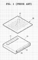
- U.S. Patent No. 5,099,311 (hereinafter referred to as the '311 patent") discloses a microchannel heatsink assembly in which microchannels are processed on a heatsink to form a plurality of micro-sized fluid pathways (see FIG.1).
- the microchannel heatsink assembly of the '311 patent is illustrated in FIG. 1.
- the heatsink assembly includes a manifold layer 10 through which a working fluid passes, and a microchannel layer 20 formed on the manifold layer 10 to cool the working fluid.
- the manifold layer 10 includes an inlet 11 through which the working fluid enters, a fluid chamber 13 in which the working fluid having been cooled by the manifold layer 10 is contained, and an outlet 15 through which the working fluid inside the fluid chamber 13 exits the fluid chamber 13.
- the microchannel layer 20 comprises microchannels 21 formed in a bottom surface thereof.
- the microchannels 21 form a plurality of fluid pathways between the inlet 11 and the fluid chamber 13 to increase a contact area between the working fluid and a front surface of the microchannel layer 20.
- the manifold layer 10 is attached onto the bottom surface of the microchannel layer 20 to uniformly supply the working fluid to the respective fluid pathways.
- the conventional heatsink assembly has a drawback in that, since the manifold layer 10 and the microchannel layer 20 are directly bonded to each other in a two-layered structure, the overall thickness of the heatsink assembly increases. As such, using the conventional heatsink assembly in a thin electronic device is difficult.
- An aspect of the present invention provides a heatsink that has thin thickness and uniformly distributes a working fluid to a plurality of fluid pathways.
- a heatsink including a cooling zone adapted to contact an object to be frozen and having microchannels formed therein to define a plurality of fluid pathways, an inlet adapted to allow a working fluid to enter therethrough, a distributor, interposed between the inlet and the cooling zone, adapted to uniformly distribute the working fluid introduced through the inlet to the microchannels, an outlet adapted to allow the working fluid, when passing through the cooling zone, to exit therethrough, and a collector, interposed between the cooling zone and the outlet, adapted to collect the working fluid passing through the microchannels.
- the object to be frozen may also be an object to be cooled.
- the heatsink may further comprise a stabilizer which is interposed between the distributor and the cooling zone and/or between the cooling zone and the collector, and has the same width and height as the cooling zone and is adapted to stabilize the flow of the distributed and/or collected working fluid.
- FIG. 2 is a plan view of a heatsink 30 according to an embodiment of the present invention.
- FIG. 3 is a side view of the heatsink of FIG. 2.
- the heatsink 30 is installed in a pipe or duct through which a working fluid enters the heatsink 30 from an external pump or tank.
- the heatsink 30 includes an inlet A through which the working fluid enters, a distributor B distributing the introduced working fluid, a cooling zone Z, a collector E collecting the working fluid that has passed through the cooling zone Z, and an outlet F through which the collected working fluid exits.
- the inlet A, the distributor B, the cooling zone Z, the collector E, and the outlet F are sequentially arranged in a direction in which the working fluid flows through the heatsink 30.
- the heatsink 30 is made of a highly heat conductive material.
- the heatsink may be made of silicon, pure copper, brass, duralumin, or aluminum.
- the working fluid may be air, liquid nitrogen, water, fluorocarbon, or the like, each of which absorbs and transfers heat.
- the cooling zone Z comprises a plurality of microchannels 35 to form a plurality of fluid pathways and contacts an object to be frozen 40.
- the object to be frozen 40 may be an integrated circuit generating a large amount of heat, such as a central processing unit (CPU) or a laser diode.
- the fluid pathways of the microchannels 35 are, in an embodiment of the invention, linear, but may be arranged in other formations. Accordingly, the fluid pathways also may have various shapes.
- the distributor B is interposed between the inlet A and the cooling zone Z, and distributes the working fluid introduced through the inlet A to the microchannels 35.
- a width of the distributor B gradually increases from the end of the inlet A to the beginning of the cooling zone Z. Also, according to an aspect of the invention, a height of the distributor B gradually decreases from the end of the inlet A to the beginning of the cooling zone Z. In this case, the distributor B uniformly distributes the working fluid, and prevents fluid deceleration by provoking less of a pressure drop between the inlet A and the cooling zone Z.
- a width of the collector E gradually decreases from the end of the cooling zone Z to the beginning of the outlet F. Also, according to an aspect of the invention, a height of the collector E gradually increases from the end of the cooling zone Z to the beginning of the outlet F.
- the collector E and the distributor B are symmetric with respect to a central vertical axis of the heatsink 30.
- the working fluid, passing through the cooling zone Z, is uniformly re-collected, such that the working fluid exits through the outlet F without a substantial change in a pressure distribution of the fluid.
- the heatsink 30 may further include a stabilizer C interposed between the distributor B and the cooling zone Z and/or between the cooling zone Z and the collector E.
- the stabilizer C has the same inner width and height as the cooling zone Z so as to provide for a stabilization of the flow of the distributed and/or collected working fluid.
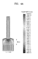
- the inclination angle ⁇ ranges from 0° to 50°. If the angle of inclination ⁇ exceeds the upper limit of 50°, as shown in FIG. 4A, the flow rate of the working fluid in a central portion of the microchannels 35 has been found to be greater than the flow rate of the working fluid in other portions of the microchannels 35, thereby failing to achieve uniform distribution of the working fluid.
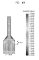
- the working fluid may be uniformly distributed to all the microchannels 35 as shown in FIG. 4B.
- the heatsink including the inlet A, the distributor B, the cooling zone Z, the collector E, and the outlet F is installed in a single pipe or duct, the overall thickness of the heatsink may be minimized. Therefore, since the working fluid is uniformly distributed to the respective fluid pathways of the microchannels 35 by optimizing the shapes of the distributor B and the collector E, cooling efficiency is enhanced.
Landscapes
- Cooling Or The Like Of Semiconductors Or Solid State Devices (AREA)
- Freezing, Cooling And Drying Of Foods (AREA)
Applications Claiming Priority (1)
| Application Number | Priority Date | Filing Date | Title |
|---|---|---|---|
| KR1020050091197A KR100772381B1 (ko) | 2005-09-29 | 2005-09-29 | 히트싱크 |
Publications (2)
| Publication Number | Publication Date |
|---|---|
| EP1770775A2 true EP1770775A2 (de) | 2007-04-04 |
| EP1770775A3 EP1770775A3 (de) | 2008-11-05 |
Family
ID=37663759
Family Applications (1)
| Application Number | Title | Priority Date | Filing Date |
|---|---|---|---|
| EP06121220A Withdrawn EP1770775A3 (de) | 2005-09-29 | 2006-09-25 | Kühler |
Country Status (6)
| Country | Link |
|---|---|
| US (1) | US7441591B2 (de) |
| EP (1) | EP1770775A3 (de) |
| JP (1) | JP2007096306A (de) |
| KR (1) | KR100772381B1 (de) |
| CN (1) | CN1941335A (de) |
| TW (1) | TWI303705B (de) |
Families Citing this family (22)
| Publication number | Priority date | Publication date | Assignee | Title |
|---|---|---|---|---|
| CN101778551B (zh) * | 2009-01-14 | 2011-11-30 | 信义汽车玻璃(深圳)有限公司 | 一种电控柜气冷散热装置 |
| CN102414329B (zh) * | 2009-05-06 | 2014-10-08 | 卢瓦塔埃斯波公司 | 生产用于火法冶金反应器的冷却元件的方法和冷却元件 |
| US20110024150A1 (en) * | 2009-07-31 | 2011-02-03 | General Electric Company | Cooling system and method for current carrying conductor |
| US20110272120A1 (en) * | 2010-03-04 | 2011-11-10 | Joshi Yogendra K | Compact modular liquid cooling systems for electronics |
| US9596785B2 (en) * | 2010-03-22 | 2017-03-14 | Pratt & Whitney Canada Corp. | Heat exchanger |
| JP5818889B2 (ja) * | 2010-07-07 | 2015-11-18 | クラー ハルクKULAH, Haluk | 電子冷却用のcmos互換性マイクロチャネルヒートシンクの製造方法 |
| TWI438388B (zh) * | 2011-05-20 | 2014-05-21 | 緯創資通股份有限公司 | 液冷式散熱裝置 |
| CN102564205B (zh) * | 2012-01-16 | 2014-06-11 | 杭州沈氏换热器有限公司 | 微通道换热器的分流结构 |
| CN102620590B (zh) * | 2012-03-30 | 2014-02-12 | 中国科学院工程热物理研究所 | 一种微通道热沉及微通道热沉性能测试装置 |
| CN102645117B (zh) * | 2012-05-02 | 2013-08-28 | 西安交通大学 | 微细通道冷却器 |
| JP5523542B1 (ja) * | 2012-12-07 | 2014-06-18 | 三菱電機株式会社 | 冷却装置 |
| JP6020256B2 (ja) * | 2013-02-28 | 2016-11-02 | 三菱マテリアル株式会社 | ヒートシンク付パワーモジュール用基板の製造方法 |
| JP6119352B2 (ja) * | 2013-03-25 | 2017-04-26 | 富士通株式会社 | 半導体装置及びその製造方法 |
| CN104717877B (zh) * | 2015-04-13 | 2017-08-04 | 蓝思科技(长沙)有限公司 | 一种用于伺服控制器或变频器中的冷却装置 |
| TWI602497B (zh) * | 2015-09-16 | 2017-10-11 | 宏碁股份有限公司 | 散熱模組 |
| US9835382B2 (en) * | 2015-09-16 | 2017-12-05 | Acer Incorporated | Thermal dissipation module |
| EP3364735A1 (de) * | 2017-02-15 | 2018-08-22 | Siemens Aktiengesellschaft | Kühlvorrichtung, umrichter mit einer kühlvorrichtung und verfahren zur kühlung eines umrichters |
| CN109714940B (zh) * | 2019-03-12 | 2020-09-25 | 陕西黄河集团有限公司 | 一种流道结构及分水器 |
| JP7300877B2 (ja) * | 2019-04-23 | 2023-06-30 | 株式会社イノアックコーポレーション | ダクト |
| US11224146B2 (en) | 2019-05-24 | 2022-01-11 | Deka Products Limited Partnership | Apparatus for electronic cooling on an autonomous device |
| CN110610911B (zh) * | 2019-09-23 | 2021-10-26 | 上海交通大学 | 一种新型三维均匀分流歧管式微通道 |
| CN110996630B (zh) * | 2019-12-26 | 2025-03-25 | 南方电网科学研究院有限责任公司 | 一种散热器 |
Family Cites Families (18)
| Publication number | Priority date | Publication date | Assignee | Title |
|---|---|---|---|---|
| JPS62286657A (ja) | 1986-06-05 | 1987-12-12 | Tohoku Daikiyasuto Kogyosho:Goushi | ヒ−トシンクの製造方法 |
| US4765397A (en) * | 1986-11-28 | 1988-08-23 | International Business Machines Corp. | Immersion cooled circuit module with improved fins |
| US5099311A (en) | 1991-01-17 | 1992-03-24 | The United States Of America As Represented By The United States Department Of Energy | Microchannel heat sink assembly |
| EP0552538B1 (de) * | 1991-12-16 | 1996-03-13 | AT&T Corp. | Wärmeabfuhr durch engkanälige Kühlrippen um elektronisches Hochleistungskomponenten zu kühlen |
| DE19514548C1 (de) * | 1995-04-20 | 1996-10-02 | Daimler Benz Ag | Verfahren zur Herstellung einer Mikrokühleinrichtung |
| US5630469A (en) * | 1995-07-11 | 1997-05-20 | International Business Machines Corporation | Cooling apparatus for electronic chips |
| US5597035A (en) * | 1995-08-18 | 1997-01-28 | Dell Usa, L.P. | For use with a heatsink a shroud having a varying cross-sectional area |
| US5810072A (en) * | 1995-09-08 | 1998-09-22 | Semipower Systems, Inc. | Forced air cooler system |
| US5936836A (en) * | 1997-12-19 | 1999-08-10 | Dell U.S.A., L.P. | Computer with an improved internal cooling system |
| US6242778B1 (en) * | 1998-09-22 | 2001-06-05 | International Business Machines Corporation | Cooling method for silicon on insulator devices |
| US6587743B1 (en) * | 1999-01-29 | 2003-07-01 | B P Microsystems, Inc. | Pick and place teaching method and apparatus for implementing the same |
| US6230791B1 (en) * | 1999-08-30 | 2001-05-15 | Electric Boat Corporation | Heat transfer cold plate arrangement |
| US6257320B1 (en) * | 2000-03-28 | 2001-07-10 | Alec Wargo | Heat sink device for power semiconductors |
| US6940716B1 (en) * | 2000-07-13 | 2005-09-06 | Intel Corporation | Method and apparatus for dissipating heat from an electronic device |
| JP3651677B2 (ja) * | 2002-07-12 | 2005-05-25 | 株式会社東芝 | 発熱素子冷却装置及び電子機器 |
| KR100555418B1 (ko) | 2002-12-16 | 2006-02-24 | 엘지전자 주식회사 | 마이크로채널 열교환기의 냉매분지 구조 |
| KR100547320B1 (ko) | 2002-12-17 | 2006-01-26 | 엘지전자 주식회사 | 마이크로채널 열교환기 |
| US7360309B2 (en) * | 2003-01-28 | 2008-04-22 | Advanced Ceramics Research, Inc. | Method of manufacturing microchannel heat exchangers |
-
2005
- 2005-09-29 KR KR1020050091197A patent/KR100772381B1/ko not_active Expired - Fee Related
-
2006
- 2006-09-13 US US11/520,012 patent/US7441591B2/en not_active Expired - Fee Related
- 2006-09-25 JP JP2006259339A patent/JP2007096306A/ja active Pending
- 2006-09-25 EP EP06121220A patent/EP1770775A3/de not_active Withdrawn
- 2006-09-28 TW TW095135918A patent/TWI303705B/zh not_active IP Right Cessation
- 2006-09-28 CN CNA2006101598145A patent/CN1941335A/zh active Pending
Also Published As
| Publication number | Publication date |
|---|---|
| KR20070036308A (ko) | 2007-04-03 |
| KR100772381B1 (ko) | 2007-11-01 |
| EP1770775A3 (de) | 2008-11-05 |
| CN1941335A (zh) | 2007-04-04 |
| US20070068652A1 (en) | 2007-03-29 |
| US7441591B2 (en) | 2008-10-28 |
| TW200716937A (en) | 2007-05-01 |
| TWI303705B (en) | 2008-12-01 |
| JP2007096306A (ja) | 2007-04-12 |
Similar Documents
| Publication | Publication Date | Title |
|---|---|---|
| EP1770775A2 (de) | Kühler | |
| US10455734B2 (en) | Cooling apparatus having vertical flow channels | |
| KR100619076B1 (ko) | 전자소자 방열용 히트싱크장치 | |
| US8505617B2 (en) | Structure and apparatus for cooling integrated circuits using copper microchannels | |
| US6422307B1 (en) | Ultra high fin density heat sink for electronics cooling | |
| JP3487382B2 (ja) | 沸騰冷却装置 | |
| US8051896B2 (en) | Apparatus for spreading heat over a finned surface | |
| US7128140B2 (en) | Heat sinks | |
| US7044212B1 (en) | Refrigeration device and a method for producing the same | |
| US7663882B2 (en) | Heat dissipating assembly having a fan duct | |
| JPH10200278A (ja) | 冷却装置 | |
| US11725885B2 (en) | Heat exchanger fin and manufacturing method of the same | |
| US7213636B2 (en) | Cooling assembly with impingement cooled heat sink | |
| JP5333161B2 (ja) | ヒートシンク | |
| US20050286232A1 (en) | Heat sink | |
| CN112400228A (zh) | 散热器 | |
| KR20060083430A (ko) | 냉각 장치 및 전자 장치 | |
| US20070039716A1 (en) | Heat dissipating unit | |
| JP7693105B2 (ja) | パワーエレクトロニクス機器を冷却するための冷却器 | |
| CN117334653A (zh) | 散热装置、电子设备和车辆 | |
| JP5163548B2 (ja) | 沸騰冷却装置 | |
| US20050145369A1 (en) | Structure of a uniform thermal conductive heat dissipation device | |
| KR101327722B1 (ko) | 전자기기의 방열장치 | |
| CN224124438U (zh) | 液冷散热器 | |
| CN121694035A (zh) | 热交换器和控制器 |
Legal Events
| Date | Code | Title | Description |
|---|---|---|---|
| PUAI | Public reference made under article 153(3) epc to a published international application that has entered the european phase |
Free format text: ORIGINAL CODE: 0009012 |
|
| 17P | Request for examination filed |
Effective date: 20060925 |
|
| AK | Designated contracting states |
Kind code of ref document: A2 Designated state(s): AT BE BG CH CY CZ DE DK EE ES FI FR GB GR HU IE IS IT LI LT LU LV MC NL PL PT RO SE SI SK TR |
|
| AX | Request for extension of the european patent |
Extension state: AL BA HR MK YU |
|
| PUAL | Search report despatched |
Free format text: ORIGINAL CODE: 0009013 |
|
| AK | Designated contracting states |
Kind code of ref document: A3 Designated state(s): AT BE BG CH CY CZ DE DK EE ES FI FR GB GR HU IE IS IT LI LT LU LV MC NL PL PT RO SE SI SK TR |
|
| AX | Request for extension of the european patent |
Extension state: AL BA HR MK RS |
|
| 17Q | First examination report despatched |
Effective date: 20081218 |
|
| AKX | Designation fees paid |
Designated state(s): DE FR GB NL |
|
| STAA | Information on the status of an ep patent application or granted ep patent |
Free format text: STATUS: THE APPLICATION IS DEEMED TO BE WITHDRAWN |
|
| 18D | Application deemed to be withdrawn |
Effective date: 20090429 |