EP1770801B1 - Batterie assemblée et méthode de fabrication - Google Patents
Batterie assemblée et méthode de fabrication Download PDFInfo
- Publication number
- EP1770801B1 EP1770801B1 EP05743376.5A EP05743376A EP1770801B1 EP 1770801 B1 EP1770801 B1 EP 1770801B1 EP 05743376 A EP05743376 A EP 05743376A EP 1770801 B1 EP1770801 B1 EP 1770801B1
- Authority
- EP
- European Patent Office
- Prior art keywords
- flat
- electrode tab
- type
- type cells
- welding
- Prior art date
- Legal status (The legal status is an assumption and is not a legal conclusion. Google has not performed a legal analysis and makes no representation as to the accuracy of the status listed.)
- Expired - Lifetime
Links
Images


Classifications
-
- H—ELECTRICITY
- H01—ELECTRIC ELEMENTS
- H01M—PROCESSES OR MEANS, e.g. BATTERIES, FOR THE DIRECT CONVERSION OF CHEMICAL ENERGY INTO ELECTRICAL ENERGY
- H01M6/00—Primary cells; Manufacture thereof
- H01M6/42—Grouping of primary cells into batteries
-
- H—ELECTRICITY
- H01—ELECTRIC ELEMENTS
- H01M—PROCESSES OR MEANS, e.g. BATTERIES, FOR THE DIRECT CONVERSION OF CHEMICAL ENERGY INTO ELECTRICAL ENERGY
- H01M50/00—Constructional details or processes of manufacture of the non-active parts of electrochemical cells other than fuel cells, e.g. hybrid cells
- H01M50/20—Mountings; Secondary casings or frames; Racks, modules or packs; Suspension devices; Shock absorbers; Transport or carrying devices; Holders
-
- H—ELECTRICITY
- H01—ELECTRIC ELEMENTS
- H01M—PROCESSES OR MEANS, e.g. BATTERIES, FOR THE DIRECT CONVERSION OF CHEMICAL ENERGY INTO ELECTRICAL ENERGY
- H01M10/00—Secondary cells; Manufacture thereof
- H01M10/04—Construction or manufacture in general
- H01M10/0413—Large-sized flat cells or batteries for motive or stationary systems with plate-like electrodes
-
- H—ELECTRICITY
- H01—ELECTRIC ELEMENTS
- H01M—PROCESSES OR MEANS, e.g. BATTERIES, FOR THE DIRECT CONVERSION OF CHEMICAL ENERGY INTO ELECTRICAL ENERGY
- H01M10/00—Secondary cells; Manufacture thereof
- H01M10/42—Methods or arrangements for servicing or maintenance of secondary cells or secondary half-cells
- H01M10/4207—Methods or arrangements for servicing or maintenance of secondary cells or secondary half-cells for several batteries or cells simultaneously or sequentially
-
- H—ELECTRICITY
- H01—ELECTRIC ELEMENTS
- H01M—PROCESSES OR MEANS, e.g. BATTERIES, FOR THE DIRECT CONVERSION OF CHEMICAL ENERGY INTO ELECTRICAL ENERGY
- H01M10/00—Secondary cells; Manufacture thereof
- H01M10/42—Methods or arrangements for servicing or maintenance of secondary cells or secondary half-cells
- H01M10/48—Accumulators combined with arrangements for measuring, testing or indicating the condition of cells, e.g. the level or density of the electrolyte
- H01M10/482—Accumulators combined with arrangements for measuring, testing or indicating the condition of cells, e.g. the level or density of the electrolyte for several batteries or cells simultaneously or sequentially
-
- H—ELECTRICITY
- H01—ELECTRIC ELEMENTS
- H01M—PROCESSES OR MEANS, e.g. BATTERIES, FOR THE DIRECT CONVERSION OF CHEMICAL ENERGY INTO ELECTRICAL ENERGY
- H01M10/00—Secondary cells; Manufacture thereof
- H01M10/60—Heating or cooling; Temperature control
- H01M10/61—Types of temperature control
- H01M10/613—Cooling or keeping cold
-
- H—ELECTRICITY
- H01—ELECTRIC ELEMENTS
- H01M—PROCESSES OR MEANS, e.g. BATTERIES, FOR THE DIRECT CONVERSION OF CHEMICAL ENERGY INTO ELECTRICAL ENERGY
- H01M10/00—Secondary cells; Manufacture thereof
- H01M10/60—Heating or cooling; Temperature control
- H01M10/62—Heating or cooling; Temperature control specially adapted for specific applications
- H01M10/625—Vehicles
-
- H—ELECTRICITY
- H01—ELECTRIC ELEMENTS
- H01M—PROCESSES OR MEANS, e.g. BATTERIES, FOR THE DIRECT CONVERSION OF CHEMICAL ENERGY INTO ELECTRICAL ENERGY
- H01M10/00—Secondary cells; Manufacture thereof
- H01M10/60—Heating or cooling; Temperature control
- H01M10/64—Heating or cooling; Temperature control characterised by the shape of the cells
- H01M10/647—Prismatic or flat cells, e.g. pouch cells
-
- H—ELECTRICITY
- H01—ELECTRIC ELEMENTS
- H01M—PROCESSES OR MEANS, e.g. BATTERIES, FOR THE DIRECT CONVERSION OF CHEMICAL ENERGY INTO ELECTRICAL ENERGY
- H01M10/00—Secondary cells; Manufacture thereof
- H01M10/60—Heating or cooling; Temperature control
- H01M10/65—Means for temperature control structurally associated with the cells
- H01M10/655—Solid structures for heat exchange or heat conduction
- H01M10/6554—Rods or plates
- H01M10/6555—Rods or plates arranged between the cells
-
- H—ELECTRICITY
- H01—ELECTRIC ELEMENTS
- H01M—PROCESSES OR MEANS, e.g. BATTERIES, FOR THE DIRECT CONVERSION OF CHEMICAL ENERGY INTO ELECTRICAL ENERGY
- H01M10/00—Secondary cells; Manufacture thereof
- H01M10/60—Heating or cooling; Temperature control
- H01M10/65—Means for temperature control structurally associated with the cells
- H01M10/655—Solid structures for heat exchange or heat conduction
- H01M10/6556—Solid parts with flow channel passages or pipes for heat exchange
- H01M10/6557—Solid parts with flow channel passages or pipes for heat exchange arranged between the cells
-
- H—ELECTRICITY
- H01—ELECTRIC ELEMENTS
- H01M—PROCESSES OR MEANS, e.g. BATTERIES, FOR THE DIRECT CONVERSION OF CHEMICAL ENERGY INTO ELECTRICAL ENERGY
- H01M10/00—Secondary cells; Manufacture thereof
- H01M10/60—Heating or cooling; Temperature control
- H01M10/65—Means for temperature control structurally associated with the cells
- H01M10/656—Means for temperature control structurally associated with the cells characterised by the type of heat-exchange fluid
- H01M10/6561—Gases
- H01M10/6566—Means within the gas flow to guide the flow around one or more cells, e.g. manifolds, baffles or other barriers
-
- H—ELECTRICITY
- H01—ELECTRIC ELEMENTS
- H01M—PROCESSES OR MEANS, e.g. BATTERIES, FOR THE DIRECT CONVERSION OF CHEMICAL ENERGY INTO ELECTRICAL ENERGY
- H01M50/00—Constructional details or processes of manufacture of the non-active parts of electrochemical cells other than fuel cells, e.g. hybrid cells
- H01M50/20—Mountings; Secondary casings or frames; Racks, modules or packs; Suspension devices; Shock absorbers; Transport or carrying devices; Holders
- H01M50/204—Racks, modules or packs for multiple batteries or multiple cells
- H01M50/207—Racks, modules or packs for multiple batteries or multiple cells characterised by their shape
- H01M50/211—Racks, modules or packs for multiple batteries or multiple cells characterised by their shape adapted for pouch cells
-
- H—ELECTRICITY
- H01—ELECTRIC ELEMENTS
- H01M—PROCESSES OR MEANS, e.g. BATTERIES, FOR THE DIRECT CONVERSION OF CHEMICAL ENERGY INTO ELECTRICAL ENERGY
- H01M50/00—Constructional details or processes of manufacture of the non-active parts of electrochemical cells other than fuel cells, e.g. hybrid cells
- H01M50/20—Mountings; Secondary casings or frames; Racks, modules or packs; Suspension devices; Shock absorbers; Transport or carrying devices; Holders
- H01M50/233—Mountings; Secondary casings or frames; Racks, modules or packs; Suspension devices; Shock absorbers; Transport or carrying devices; Holders characterised by physical properties of casings or racks, e.g. dimensions
- H01M50/24—Mountings; Secondary casings or frames; Racks, modules or packs; Suspension devices; Shock absorbers; Transport or carrying devices; Holders characterised by physical properties of casings or racks, e.g. dimensions adapted for protecting batteries from their environment, e.g. from corrosion
-
- H—ELECTRICITY
- H01—ELECTRIC ELEMENTS
- H01M—PROCESSES OR MEANS, e.g. BATTERIES, FOR THE DIRECT CONVERSION OF CHEMICAL ENERGY INTO ELECTRICAL ENERGY
- H01M50/00—Constructional details or processes of manufacture of the non-active parts of electrochemical cells other than fuel cells, e.g. hybrid cells
- H01M50/50—Current conducting connections for cells or batteries
- H01M50/502—Interconnectors for connecting terminals of adjacent batteries; Interconnectors for connecting cells outside a battery casing
- H01M50/509—Interconnectors for connecting terminals of adjacent batteries; Interconnectors for connecting cells outside a battery casing characterised by the type of connection, e.g. mixed connections
- H01M50/51—Connection only in series
-
- H—ELECTRICITY
- H01—ELECTRIC ELEMENTS
- H01M—PROCESSES OR MEANS, e.g. BATTERIES, FOR THE DIRECT CONVERSION OF CHEMICAL ENERGY INTO ELECTRICAL ENERGY
- H01M50/00—Constructional details or processes of manufacture of the non-active parts of electrochemical cells other than fuel cells, e.g. hybrid cells
- H01M50/50—Current conducting connections for cells or batteries
- H01M50/502—Interconnectors for connecting terminals of adjacent batteries; Interconnectors for connecting cells outside a battery casing
- H01M50/514—Methods for interconnecting adjacent batteries or cells
- H01M50/516—Methods for interconnecting adjacent batteries or cells by welding, soldering or brazing
-
- H—ELECTRICITY
- H01—ELECTRIC ELEMENTS
- H01M—PROCESSES OR MEANS, e.g. BATTERIES, FOR THE DIRECT CONVERSION OF CHEMICAL ENERGY INTO ELECTRICAL ENERGY
- H01M50/00—Constructional details or processes of manufacture of the non-active parts of electrochemical cells other than fuel cells, e.g. hybrid cells
- H01M50/50—Current conducting connections for cells or batteries
- H01M50/543—Terminals
- H01M50/547—Terminals characterised by the disposition of the terminals on the cells
- H01M50/548—Terminals characterised by the disposition of the terminals on the cells on opposite sides of the cell
-
- H—ELECTRICITY
- H01—ELECTRIC ELEMENTS
- H01M—PROCESSES OR MEANS, e.g. BATTERIES, FOR THE DIRECT CONVERSION OF CHEMICAL ENERGY INTO ELECTRICAL ENERGY
- H01M50/00—Constructional details or processes of manufacture of the non-active parts of electrochemical cells other than fuel cells, e.g. hybrid cells
- H01M50/50—Current conducting connections for cells or batteries
- H01M50/569—Constructional details of current conducting connections for detecting conditions inside cells or batteries, e.g. details of voltage sensing terminals
-
- H—ELECTRICITY
- H01—ELECTRIC ELEMENTS
- H01M—PROCESSES OR MEANS, e.g. BATTERIES, FOR THE DIRECT CONVERSION OF CHEMICAL ENERGY INTO ELECTRICAL ENERGY
- H01M6/00—Primary cells; Manufacture thereof
- H01M6/42—Grouping of primary cells into batteries
- H01M6/46—Grouping of primary cells into batteries of flat cells
-
- H—ELECTRICITY
- H01—ELECTRIC ELEMENTS
- H01M—PROCESSES OR MEANS, e.g. BATTERIES, FOR THE DIRECT CONVERSION OF CHEMICAL ENERGY INTO ELECTRICAL ENERGY
- H01M2220/00—Batteries for particular applications
- H01M2220/20—Batteries in motive systems, e.g. vehicle, ship, plane
-
- Y—GENERAL TAGGING OF NEW TECHNOLOGICAL DEVELOPMENTS; GENERAL TAGGING OF CROSS-SECTIONAL TECHNOLOGIES SPANNING OVER SEVERAL SECTIONS OF THE IPC; TECHNICAL SUBJECTS COVERED BY FORMER USPC CROSS-REFERENCE ART COLLECTIONS [XRACs] AND DIGESTS
- Y02—TECHNOLOGIES OR APPLICATIONS FOR MITIGATION OR ADAPTATION AGAINST CLIMATE CHANGE
- Y02E—REDUCTION OF GREENHOUSE GAS [GHG] EMISSIONS, RELATED TO ENERGY GENERATION, TRANSMISSION OR DISTRIBUTION
- Y02E60/00—Enabling technologies; Technologies with a potential or indirect contribution to GHG emissions mitigation
- Y02E60/10—Energy storage using batteries
-
- Y—GENERAL TAGGING OF NEW TECHNOLOGICAL DEVELOPMENTS; GENERAL TAGGING OF CROSS-SECTIONAL TECHNOLOGIES SPANNING OVER SEVERAL SECTIONS OF THE IPC; TECHNICAL SUBJECTS COVERED BY FORMER USPC CROSS-REFERENCE ART COLLECTIONS [XRACs] AND DIGESTS
- Y02—TECHNOLOGIES OR APPLICATIONS FOR MITIGATION OR ADAPTATION AGAINST CLIMATE CHANGE
- Y02P—CLIMATE CHANGE MITIGATION TECHNOLOGIES IN THE PRODUCTION OR PROCESSING OF GOODS
- Y02P70/00—Climate change mitigation technologies in the production process for final industrial or consumer products
- Y02P70/50—Manufacturing or production processes characterised by the final manufactured product
-
- Y—GENERAL TAGGING OF NEW TECHNOLOGICAL DEVELOPMENTS; GENERAL TAGGING OF CROSS-SECTIONAL TECHNOLOGIES SPANNING OVER SEVERAL SECTIONS OF THE IPC; TECHNICAL SUBJECTS COVERED BY FORMER USPC CROSS-REFERENCE ART COLLECTIONS [XRACs] AND DIGESTS
- Y10—TECHNICAL SUBJECTS COVERED BY FORMER USPC
- Y10T—TECHNICAL SUBJECTS COVERED BY FORMER US CLASSIFICATION
- Y10T29/00—Metal working
- Y10T29/49—Method of mechanical manufacture
- Y10T29/49002—Electrical device making
- Y10T29/49108—Electric battery cell making
Definitions
- This invention relates to a combined battery for which ultrasonic welding of electrode tabs themselves of flat-type cells is easily performed and a method for producing the same.
- An automobile is desired to mount a compact-size and light-weight battery, capable of charging and discharging high power frequently, and excellent in vibration resistance and heat radiation performance.
- a combined battery constructed by connecting a large number of flat-type cells in series has recently been developed as shown in JP-A-2004-31136 .
- US 5,230,967 A teaches a battery, which comprises a stack of electrochemical cell units each comprising a positive electrode, a solid electrolyte and a negative electrode, the electrodes of the cell units being interconnected by means of a plurality of connector devices each comprising a base section, which are connected to an electrode and a pair of contact sections extending from the cell unit, the devices being arranged in two stacks with the pairs of contact sections of the devices in each stack overlying one another to form two sets of contact sections, adjacent contact sections of each set being interconnected with successive interconnections throughout each stack of connector devices alternating between the two sets of contact sections.
- WO 00/41253 A describes a cell unit, which includes at least two flat electrochemical cells and a circuit board, wherein the cells are folded onto one or both sides of the circuit board whereby the circuitry on the circuit board is protected. Further described is a means of connecting electrochemical cells to a circuit board, wherein protruding parts of the cell, at the terminal end, are bonded to the circuit board.
- US 5,585,206 A teaches anode and cathode sections of a battery cell, which include current collectors with exposed portions.
- the exposed portions contain slits which form tabs. These tabs can be spot welded together to form connections between the electrode sections.
- a prismatic battery module which includes a prismatic battery case having a plurality of prismatic cell cases connected to one another through separation walls, a planar electroconductive connector forming part of the separation wall between the cell cases, an electrode plate group arranged in each cell case, and an electrolyte placed in each cell case. Lead portions of positive electrode plates and negative electrode plates of the electrode plate group are directly connected to the electroconductive connector.
- the prismatic battery module requires fewer connection points and provides shorter electrical communication paths, thereby reducing internal resistance.
- JP 9 147830 A teaches a flat-type battery cell. However, not disclosed is a battery in which a plurality of such battery cells are stacked and connected to each other.
- JP 2003-346780 A describes means for effectively preventing short circuit in a battery due to contact between electrode tabs in the battery.
- a battery pack device which comprises a battery pack, which is constructed by overlapping a plurality of battery cells that have protruded electrode tabs and in which the battery cells are connected in series by connecting a pair of electrode tabs for the mutually adjoining battery cells and an insulating body in which a plurality of slits are provided corresponding locationally to each of a pair of electrodes tabs mutually connected and the pair of the electrode tabs that are mutually connected are inserted in each of the slits.
- JP 2003-346748 A relates to a battery assembly unit having a reduced size by optimizing the layout of a base plate on which, a balancer circuit is mounted.
- the battery assembly and the base plate on which the balancer circuit is mounted are housed in a box.
- the battery assembly is formed by stacking a plurality of battery cells, wherein each battery cell has an electrode tub protruding outward, and the battery cells are serially connected to each other by connecting the electrode tubs.
- the base plate put on the battery assembly unit is connected to the electrode tubs of respective battery cells.
- US 2003/224246 A1 teaches a battery, which comprises at least two unit cells. Each of the at least two unit cells is provided with an outer sheath film composed of polymer-metal composite material, a positive-electrode current collector, a negative-electrode current collector, a separator disposed between the positive-electrode current collector and the negative-electrode current collector, one positive electrode tab to which the positive-electrode current collector is connected and protruding from a first sealed portion of the outer sheath film, one negative electrode tab to which the negative-electrode current collector is connected and protruding from a second sealed portion of the outer sheath film, a first polymer layer disposed between the positive electrode tab and the outer sheath film, and a second polymer layer disposed between the negative electrode tab and the outer sheath film.
- JP 2004-014317 A discloses a battery comprising cell units, which are directly serially welded and US 2003/113621 A1 teaches a battery, which includes a battery enclosure, a power-generating unit accommodated in the battery enclosure, positive and negative terminal electrodes.
- the battery enclosure is composed of a laminate film compounded of metal and a polymer material, and has a rectangular shape.
- the power-generating unit includes positive electrode collectors, negative electrode collectors and separators.
- the positive and negative terminal electrodes have dimensions substantially equal to those of the positive and negative electrode collectors, respectively. Further, the positive and negative terminal electrodes protrude from mutually different sides of the battery enclosure.
- the positive terminal electrode is formed by protruding the positive electrode collectors from the battery enclosure in a state where end portions of the positive electrode collectors are mutually stacked.
- the negative terminal electrode is formed by protruding the negative electrode collectors from the battery enclosure in a state where end portions of the negative electrode collectors are mutually stacked.
- a combined battery providing higher voltage is desired so as to charge and discharge high power in high efficiency.
- a combined battery providing higher voltage requires connecting a plurality of flat-type cells in series to construct the combined battery.
- electrode tabs are welded by laminating thereof so that the directions of electrode tabs of the flat-type cells, the plus and the minus, are made alternate, composing a set of the plus and the minus electrode tabs of the laminated flat-type cells, and welding the plus and the minus electrode tabs themselves to compose a set, by using an ultrasonic welding machine or by using mechanical means including washers and the like, in order from the bottom or the top in the lamination direction.
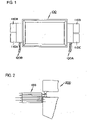
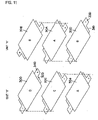
- Fig. 1 is an outline view of a combined battery according to Embodiment 1 (not falling under the scope of the present invention).
- the combined battery 100 according to the present Embodiment includes 8 sheets of flat-type cells by laminating thereof in the thickness direction thereof so that polarity of electrode tabs is alternately set.
- the combined battery 100 according to the present Embodiment includes welding parts of the electrode tabs to connect the flat-type cells themselves in series, to compose a set when all the flat-type cells are laminated, separating at a plurality of positions of the combined battery, and such a structure that all the flat-type cells are electrically connected in series by welding each of the welding parts.
- the flat-type cell is rectangular in shape when viewed from the top and the welding parts of electrode tabs are arranged so that the positions thereof may be changed in the length direction (the horizontal direction in the figure) thereof or in the shorter-length direction (the vertical direction in the figure) thereof in each lamination layer position. Therefore each one of electrode tabs pulled out from both sides of the flat-type cell has a specific shape in each lamination layer position so that each set of electrode tabs when 8 sheets of the flat-type cells are laminated, may be separated into 4 directions thereof.
- an insulating sheet is inserted between all the flat-type cells to provide a function to detect voltage of each one of the flat-type cells and to insulate between the electrode tabs to be insulated.
- the insulating sheet has a specific shape like that of the electrode tab in each lamination layer position to provide the above-mentioned functions.
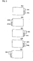
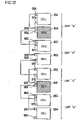
- a combined battery 100 is composed of all the flat-type cells electrically connected in series by welding electrode tabs of the flat-type cells laminated by using the ultrasonic welding machine 200 shown in Fig. 2 .
- the electrode tabs of the combined battery include the 4 protruding parts thereof separated in 4 directions as shown in Fig. 1 .
- ultrasonic welding of a group of electrode tabs 110A is capable of connecting the flat-type cell located at the top and the lower next themselves in series
- ultrasonic welding of a group of electrode tabs 110B is capable of connecting the flat-type cell located at the third top and the lower next themselves in series
- ultrasonic welding of a group of electrode tabs 110C is capable of connecting the flat-type cell located at the third bottom and the upper next themselves in series
- ultrasonic welding of a group of electrode tabs 110D is capable of connecting the flat-type cell located at the bottom and the upper next themselves in series.
- a voltage detection terminal to provide the function to detect voltage of a flat-type cell is installed at one surface side thereof.
- a lead wire is connected to the voltage detection terminal, a group of 4 lead wires 120A from one side of the combined battery 100 and a group of 3 lead wires 120B from the other side thereof are pulled out.
- Each two of the lead wires is connected to a voltage detector, not shown in the figure, so that operating state of each flat-type cell may be checked by monitoring voltage thereof.
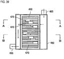
- the combined batteries are laminated in 3 layers thereof with heat sinks presented inter-the combined batteries, the 3 lamination layers are arranged in 4 rows, and all of the combined batteries are fixed with heat sinks so as to be sandwiched from both sides in the lamination direction thereof.
- Heat sinks presented at both sides in the lamination direction are fixed so as to attract each other with specified force. Therefore specified compression strength is evenly applied to every flat-type cell.
- connection of electrode tabs of each combined battery in 2 to 4 rows also are conducted similarly as in the first row. And electrode tabs of each combined battery located at the bottom are connected by welding to the bus-bars 130A and 130B, and electrode tabs of each combined battery located at the top are connected by welding to the bus-bar 130C.
- the combined battery 100 according to the present Embodiment has at least one of the plus side or the minus side of the electrode tab with a L-character shape, except the flat-type cell 10A shown in Fig. 4 , to separate welding parts of the electrode tabs into 4 directions and makes the shape of the electrode tab of each flat-type cell different according to the position of lamination layer so that welding parts of the electrode tabs are separated into a plurality of positions when the flat-type cell are laminated.
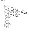
- Fig. 4 shows the types of flat-type cells (electrode tab shapes are different) required for constructing the combined battery 100 according to the present Embodiment. While the combined battery 100 is composed of 8 laminated sheets of flat-type cells, the flat-type cells having 6 types of electrode tab shapes, as shown in the figure, are necessary to separate welding positions of the electrode tabs into 4 directions.
- the flat-type cell 10A located at the bottom is one having electrode tabs with the same rectangular shape at both sides.
- the flat-type cell 10B located at the second bottom has the electrode tab 11B at one side with the same rectangular shape as the electrode tab of the flat-type cell 10A, and has the electrode tab 12B at the other side with an inverted L-character shape.
- the flat-type cell 10C located at the third bottom has the electrode tab 11C at one side with the inverted L-character shape and has the electrode tab 12C at the other side with the rectangular shape.
- the flat-type cell 10D located at the fourth bottom has the electrode tab 11D at one side with the rectangular shape, and has the electrode tab 12D at the other side with the inverted L-character shape.
- the flat-type cell 10E located at the fifth bottom has the electrode tab 11E at one side with an inverted and further turned upside down L-character shape, and has the electrode tab 12E at the other side with the inverted L-character shape like the flat-type cell 10D.
- the flat-type cell 10F located at the six bottom has the electrode tab 11F with the inverted and further turned upside down L-character shape like the flat-type cell 10E and has the electrode tab 12F at the other side with the rectangular shape.
- the flat-type cell located at the top the same one as the flat-type cell 10C is laminated, and as the flat-type cell located at the second top, the same one as the flat-type cell 10B is laminated.
- Types of the flat-type cells to be prepared are described above on the assumption that the flat-type cell can not be laminated by turning inside out thereof. However, if the flat-type cell can be laminated by turning inside out thereof, the flat-type cell 10B turned inside out can commonly be used as the flat-type cell 10D, and the flat-type cell 10C turned inside out can be commonly used as well as the flat-type cell 10F, and in this case preparation of only 4 types of flat-type cells is required.
- insulating sheets are used for insulating between the flat-type cells and detecting voltage of a flat-type cell.
- An insulating sheet is made changed in shape like the flat-type cell according to the lamination layer position thereof.
- Fig. 5 shows types of the insulating sheets required for constructing the combined battery 100 according to the present Embodiment. 5 Types of the insulating sheets as shown in the Figure are necessary for insulating between the flat-type cells to be insulated.
- the insulating sheet 20A is one formed with the electrode tab insulating part 22A at the position, for example, corresponding to the electrode tab 12A of the flat-type cell 10A, for example, having no protruding part at the electrode tab , and the voltage detecting terminal 24A is installed at the electrode tab insulating part 22A.
- the voltage detecting terminal 24A is bonded on one side of the electrode tab insulating part 22A. Therefore the voltage detecting terminal 24A provides voltage of a flat-type cell through an electrode tab contacting with the terminal when laminated.
- a lead wire is connected to the voltage detecting terminal 24A, and is connected to a voltage detector or the like located outside.
- the position, where the electrode tab insulating part 22B is installed is 180 degrees different in angle.
- the voltage detecting terminal 24B is bonded on the electrode tab insulating part 22B.
- the insulating sheet 20C is one formed with the electrode tab insulating part 22C at the position, for example, corresponding to the inverted L-character shape electrode tab 12B of the flat-type cell 10B, for example, having a protruding part at the electrode tab, and the voltage detecting terminal 24C is bonded at a not-protruding part of the electrode tab insulating part 22C.
- the insulating sheet 20D is different from the insulating sheet 20C in that the electrode tab insulating part 22C has L-character shape.
- the voltage detecting terminal 24D is installed at a not-protruding part of the electrode tab insulating part 22D.
- the position, where the electrode tab insulating part 22E is installed is 180 degrees different in angle.
- the voltage detecting terminal 24E is bonded on the electrode tab insulating part 22E.
- the flat-type cells and the insulating sheets are arranged as shown in Fig. 6 and laminated as shown in Fig. 7 . Specifically, from the bottom to the top, the flat-type cell 10A shown in Fig. 4 , the insulating sheet 20A shown in Fig.
- the flat-type cell 10B, the insulating sheet 20B, the flat-type cell 10C, the insulating sheet 20C, the flat-type cell 10D, the insulating sheet 20B, the flat-type cell 10E, the insulating sheet 20D, the flat-type cell 10F, the insulating sheet 20E, the flat-type cell 10B, the insulating sheet 20A and the flat-type cell 10C are laminated in order.
- units are produced in advance by ultrasonic welding of the electrode tabs themselves indicated by X-mark in Fig. 6 .
- the number of units produced in advance is 3 units as shown in Fig. 6 .
- a plurality of units are produced by welding the electrode tabs themselves of the flat-type cells with making an insulating body present inter-the flat-type cells to compose a set. That is, the insulating sheet 20A is placed on the flat-type cell 10A and further the flat-type cell 10B is placed thereon. The insulating sheet 20A is arranged so that the voltage detecting terminal 24A may contact with the plus side electrode tab 12B of the flat-type cell 10B. Ultrasonic welding is applied to the plus side electrode tab 12A of the flat-type cell 10A, and the minus side electrode tab 11B of the flat-type cell 10B.
- the unit including the flat-type cells 10A and 10B with the insulating sheet 20A in sandwiched state therebetween is formed.
- the formation of a unit is performed as well for the unit including the flat-type cells 10C and 10D with the insulating sheet 20C in sandwiched state therebetween and the unit including the flat-type cells 10B and 10F with the insulating sheet 20E in sandwiched state therebetween.
- the flat-type cells and the insulating bodies are laminated so that the flat-type cells and the insulating body are alternatively laminated in combination of the units, the flat-type cells themselves and the insulating bodies, and welding parts of the electrode tabs to connect the flat-type cells themselves in series, to compose a set when all the flat-type cells are laminated, are separated at different positions. That is, when the flat-type cells and the insulating bodies combined with the units produced as described above, are laminated as shown in Fig.7 , the combined battery 100 is formed with the appearance as shown in Fig. 1 .
- the ultrasonic welding machine 200 When the combined battery 100 with all the electrode tabs in not yet welded state, is set to the ultrasonic welding machine 200 and the group of electrode tabs 110A is first subjected to ultrasonic welding as shown in Fig. 2 , the minus side electrode tab 11C of the flat-type cell 10C located at the top, and the plus side electrode tab 12B of the flat-type cell 10B located at the second top are welded.
- the part where ultrasonic welding is applied is the protruding parts of the electrode tab 11C and the electrode tab 12B, indicated by A-mark in the figure.
- the electrode tabs 11B and 12F thereof are already welded, and the electrode tab insulating part 22A of the insulating sheet 20A, insulates the electrode tab 12C of the flat-type cell 10C from the electrode tab 11B of the flat-type cell 10B, and the electrode tab insulating part 22E of the insulating sheet 20E insulates the electrode tab 12B of the flat-type cell 10B from the electrode tab 11F of the flat-type cell 10F, therefore 3 sheets of the flat-type cells 10C,10B and 10F are electrically connected in series by welding a group of the electrode tabs 110A.
- voltage of the flat-type cell 10C can be detected by measuring voltage between the voltage detecting terminals 24A and 24E.
- the electrode tab insulating part 22D of the insulating sheet 20D insulates the electrode tab 12F of the flat-type cell 10F from the electrode tab 11E of the flat-type cell 10E, 4 sheets of the flat-type cells 10C, 10B, 10F and 10E are electrically connected in series by welding a group of the electrode tabs 110B.
- voltage of the flat-type cell 10B can be detected by measuring voltage between the voltage detecting terminals 24E and 24D.
- the electrode tab insulating part 22B of the insulating sheet 20B insulates the electrode tab 12E of the flat-type cell 10E from the electrode tab 11D of the flat-type cell 10D
- the electrode tab insulating part 22C of the insulating sheet 20C insulates the electrode tab 12D of the flat-type cell 10D from the electrode tab 11C of the flat-type cell 10C, therefore 6 sheets of the flat-type cells 10C, 10B, 10F, 10E, 10D and 10C are electrically connected in series by welding a group of the electrode tabs 110C.
- voltage of the flat-type cell 10F can be detected by measuring voltage between the voltage detecting terminals 24D and 24B
- voltage of the flat-type cell 10E can be detected by measuring voltage between the voltage detecting terminals 24B and 24C.
- the welding parts separated at different positions are welded in order.
- a group of the electrode tabs 110D (refer to Fig. 2 ) is subjected to ultrasonic welding, the minus side electrode tab 11C of the flat-type cell 10C, and the plus side electrode tab 12B of the flat-type cell 10B located lower next, are welded.
- the part where ultrasonic welding is applied is the protruding parts of the electrode tab 11C and the electrode tab 12B, indicated by A-mark in the figure.
- the electrode tabs 11B and 12A thereof are already welded.
- the electrode tab insulating part 22B of the insulating sheet 20B insulates the electrode tab 12C of the flat-type cell 10C from the electrode tab 11B of the flat-type cell 10B
- the electrode tab insulating part 22A of the insulating sheet 20A insulates the electrode tab 12B of the flat-type cell 10B from the electrode tab 11A of the flat-type cell 10A, all of 8 sheets of the flat-type cells 10C, 10B, 10F, 10E, 10D, 10C, 10B and 10A composing the combined battery 100, are electrically connected in series by welding a group of the electrode tabs 110D.
- voltage of the flat-type cell 10D can be detected by measuring voltage between the voltage detecting terminals 24C and 24B
- voltage of the flat-type cell 10C can be detected by measuring voltage between the voltage detecting terminals 24B and 24A.
- the combined battery 100 can be produced by using 8 sheets of the flat-type cells and the 7 sheets of the insulating sheets, laminating the flat-type cells and the insulating sheets alternatively, and ultrasonic welding the electrode tab groups 110A to 110D, separated at 4 positions. Because the positions to be subjected to ultrasonic welding are dispersed at 4 directions, all of the flat-type cells enable to be welded while in lamination state. Therefore freedom of the head shape of the ultrasonic welding machine becomes greater and automation of welding operation becomes easy. And because ultrasound is used for welding and no mechanical bonding part is present, it is unlikely that contact resistance varies and loosening due to vibration occurs and thus sufficient reliability can be kept in endurance-reliability and maintainability.
- the insulating sheet needs to be placed between the flat-type cells, once the insulating sheet is laminated, insulation between the electrode tabs can be secured and furthermore because the voltage detecting terminal is bonded, connecting only the voltage detecting terminal to the electrode tab is unnecessary and workability is improved. Furthermore, when the insulating sheet is provided with moderate elasticity and moderate surface friction, which in turn leads to provide moderate pressure to the flat-type cells laminated, and to prevent misalignment of the flat-type cells.
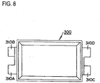
- Fig. 8 is an outline view of a combined battery according to Embodiment 2 relevant to the present invention.
- a combined battery 300 according to the present Embodiment is one formed by laminating 12 sheets of flat-type cells in the thickness direction of thereof.
- Each one of electrode tabs pulled out from both sides of the flat-type cell has a specific shape in each lamination layer position thereof so that welding positions are different each other, when 12 sheets of the flat-type cells are laminated in order.
- the electrode tabs of the flat-type cells are electrically connected in series by welding with the ultrasonic welding machine 200 shown in Fig. 2 .
- the electrode tabs of the combined battery 300 are arranged so that the protruding parts 310A, 310B, 310C and 310D thereof are separated into 4 directions as shown in Fig. 8 in completely assembled state.
- the flat-type cell 300 all of the 12 sheets of flat-type cells are electrically connected in series in completely assembled state.
- the combined batteries are laminated so as to form 2 lamination layers thereof with heat sinks made present inter-the combined batteries, the 2 laminated layers are set in 4 rows and all of the combined batteries are fixed with heat sinks so as to be sandwiched from both sides in the lamination direction thereof.
- Heat sinks present at both sides in the lamination direction are fixed so as to attract each other with specified force. Therefore specified suppress strength is evenly applied to every flat-type cell.
- the 8 combined batteries including 2 layers by 4 rows are all connected in series similarly as in Embodiment 1, by directly connecting the electrode tabs themselves which are located in the lamination direction, and by connecting, with bus-bars, the electrode tabs themselves which are adjacently located at the top or the bottom thereof.
- the combined battery 300 according to the present Embodiment makes the shape of the electrode tab of each of flat-type cells different according to the position of lamination layer so that welding parts of the electrode tabs are separated into 4 directions.
- Fig. 9 shows the types of flat-type cells (electrode tab shapes are different) required for constructing the combined battery 300 according to the present Embodiment. While the combined battery 300 is composed of 12 laminated sheets of the flat-type cells, the flat-type cells having 4 types of electrode tab shapes as shown in the Figure, are necessary to separate the welding positions of the electrode tabs into 4 directions.
- the A type flat-type cell 30A has the minus side electrode tab 31A cut off at the left side as viewed from the end thereof, and the plus side electrode tab 32A cut off at the right side as viewed from the end thereof.
- the B type flat-type cell 30B has the electrode tabs 31B and 32B of both sides thereof, cut off both at the right side as viewed from each of the ends thereof, and has the protruding parts 33B and 34B at the left side as viewed from each of the ends thereof.
- the C type flat-type cell 30C has the minus side electrode tab 31C cut off at the right side as viewed from the end thereof, and the plus side electrode tab 32C cut off at the left side as viewed from the end thereof.
- the D type flat-type cell 30D has the electrode tabs 31D and 32D of both sides thereof, cut off both at the left side as viewed from each of the ends thereof, and has the protruding parts 33D and 34D at the right side as viewed from each of the ends thereof.
- Types of the flat-type cells to be prepared are described above on the assumption that the flat-type cell can not be laminated by turning inside out thereof. However, if the flat-type cell can be laminated by turning inside out thereof, the flat-type cell 30A turned inside out can commonly be used as the flat-type cell 30C, and the flat-type cell 30B turned inside out can commonly be used as well as the flat-type cell 30D, and in this case preparation of only 2 types of flat-type cells is required.
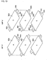
- the flat-type cells are arranged as shown in Fig. 10 and Fig. 11 , and laminated as shown in Fig. 12 . Specifically, from the bottom to the top, the flat-type cells 30A, 30C, 30D, 30D, 30A, 30B, 30C, 30D, 30A, 30C, 30D and 30D shown in Fig. 8 are laminated in order.
- a unit (the first unit) is produced in advance by combining the flat-type cells including 3 sheets therein shown in Fig. 10 and Fig. 11 , and by ultrasonic welding the electrode tabs themselves.
- the unit “a” composed of the combination of the flat-type cells 30D, 30D and 30C
- the unit “b” composed of the combination of the flat-type cells 30A, 30D and 30C
- the unit “c” composed of the combination of the flat-type cells 30B,30A and 30D
- the unit “d” composed of the combination of the flat-type cells 30D,30C and 30A, totally 4 units, are produced in advance.
- the electrode tabs connected by the dotted line shown in Figs. 10 and 11 are welded themselves with the ultrasonic welding machine 200 shown in Fig. 2 .
- the unit "a" composed of the combination of the flat-type cells 30D, 30D and 30C
- first the protruding part 34C of the plus side electrode tab 32C of the flat-type cell 30C located at the bottom, and the protruding part 33D of the minus side electrode tab 31D of the flat-type cell 30D located upper next are welded, next the protruding part 33D of the minus side electrode tab 31D of the flat-type cell 30D located at the top, and the protruding part 34D of the plus side electrode tab 32D of the flat-type cell 30D located lower next, are welded. If welding is performed in order described above, because welding can be performed at entirely different positions, welding operation is easy.
- the insulating body 40 As an insulation means, is made present inter-the electrode tabs 32D and 31D as shown in Fig. 12 .
- the insulating body 40 a sheet-like one can be accepted or an insulating tape can be bonded on the lower face (in the direction in the Figure) of the electrode tab 32D as well.
- the insulating body 40 is made present inter-the electrode tabs 32D and 31C.
- the remaining 3 units shown in Figs. 10 and 11 are produced in the same way as described above.
- the drawings with the same shape as the insulating body 40 are all insulating bodies to insulate between the electrode tabs.
- the unit ⁇ (the second unit) is produced by welding the unit “a” and the unit “b” as shown in Fig. 12 .
- welding of the unit “a” and the unit “b” is performed by welding the protruding part 33C of the electrode tab 31C of the flat-type cell 30C located at the bottom of the unit "a", and the protruding part 34A of the electrode tab 31A of the flat-type cell 30A located at the top of the unit "b”.
- the unit ⁇ is produced by welding the unit "c” and the unit "d”. As shown in Fig.
- welding of the unit “c” and the unit “d” is performed by welding the protruding part 33D of the electrode tab 31D of the flat-type cell 30D located at the bottom of the unit "c", and the protruding part 34D of the electrode tab 32D of the flat-type cell 30D located at the top of the unit "d".
- welding of the units is performed as above, because the protruding parts to be object of welding are located at the positions not interrupted at all by other parts, welding operation is easy.
- the combined battery according to the present Embodiment is produced by welding the unit ⁇ and the unit ⁇ .
- Welding of the unit ⁇ and the unit ⁇ is performed, as shown in Fig. 12 , by welding the protruding part 33C of the electrode tab 31C of the flat-type cell 30C located at the bottom of the unit ⁇ , and the protruding part 34B of the electrode tab 32B of the flat-type cell 30B located at the top of the unit ⁇ .
- welding of the unit ⁇ and the unit ⁇ is performed as above, because the protruding parts to be object of welding are located at the positions not interrupted at all by other parts, welding operation is easy.
- the combined battery according to the present Embodiment is formed by producing the units “a”, “b”, “c”, and “d”, then producing the unit ⁇ by welding the units “a” and “b”, and the unit ⁇ by welding the units “c” and “d”, and finally producing the combined battery by welding the units ⁇ and ⁇ so as to form a combined battery, and because welding of all the units can be performed at the positions not interrupted by other electrode tabs, welding operation is easy. Accordingly, freedom of the head shape of the ultrasonic welding machine becomes greater and automation of welding operation becomes easy. And because ultrasound is used for welding and no mechanical bonding part is present, it is unlikely that contact resistance varies or loosening due to vibration occurs, and thus sufficient reliability can be kept in endurance-reliability and maintainability.
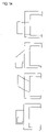
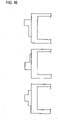
- Figs. 13 to 16 show other Embodiments of the flat-type cells required for constructing the combined battery, wherein only the 1 st figure in Fig. 13 and the 1 st and 2 nd figure in Fig. 16 are in accordance with the present invention.
- the shape of the electrode tab is designed to be L-character and extending into 2 directions with newly adding the protruding part to the electrode tab of an ordinary flat-type cell.
- the shape of the electrode tab is designed to be L-character and extending into 2 directions by cutting off a part of the electrode tab of an ordinary flat-type cell.
- the shapes extending into 2 directions and in Fig.
- electrode tabs are capable of being welded at different positions of an already assembled battery or to be welded at different positions during steps for assembling a combined battery.
- a combined battery according to the present Embodiment is one formed by laminating 8 sheets of flat-type cells in the thickness direction thereof in the prescribed combination of the flat-type cells having 3 types of electrode tab shapes as shown in Fig. 17 .
- Each one of electrode tabs pulled out from both sides of the flat-type cell has a specific shape in each lamination layer position thereof so that welding positions may be in different positions when 8 sheets of the flat-type cells are laminated in order.
- the electrode tabs of the flat-type cells are electrically connected in series by welding with the ultrasonic welding machine 200 shown in Fig. 2 .
- the electrode tabs of the combined battery are arranged so that the protruding parts thereof are separated into 4 directions in the same way as Fig. 8 shown in Embodiment 2 in completely assembled state. In the combined battery, all of the 8 sheets of flat-type cells are electrically connected in series, in completely assembled state.
- the combined battery according to the present Embodiment makes the shapes of the electrode tab of each of flat-type cells different according to the position of lamination layer so that welding parts of the electrode tabs are separated into 4 directions.
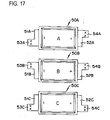
- Fig. 17 shows the types of flat-type cells (electrode tab shapes are different) required for constructing the combined battery according to the present Embodiment. While the combined battery is composed of 8 laminated sheets of flat-type cells, the flat-type cells having 3 types of electrode tab shapes as shown in the Figure are used to separate welding positions of the electrode tabs into 4 directions in the present Embodiment.
- the A type flat-type cell 50A has the minus side electrode tab 51A and the plus side electrode tab 52A, cut off both at the left side as viewed from each of the ends thereof, and has the protruding parts 53A and 54A at the right side as viewed from each of the ends thereof.
- the B type flat-type cell 50B has the minus side electrode tab 51B cut off at the right side as viewed from the end thereof, and the plus side electrode tab 52B cut off at the left side as viewed from the end thereof, and has the protruding part 53B at the left side and the protruding part 53D at the right side.
- the C type flat-type cell 50C has the minus side electrode tab 51C cut off at the left side as viewed from the end thereof and the plus side electrode tab 52C cut off at the right side as viewed from the end thereof, and has the protruding part 53C at the right side and the protruding part 54C at the left side.
- the flat-type cells 50A to 50C have the electrode tabs rectangular in shape (before a tab is cut off).
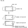
- Three types of the flat-type cells 50A to 50C, as shown in Fig. 17 are produced by cutting a part of the electrode tab. While various methods for cutting thereof can be found out, as shown in Fig. 18 , the size of the combined battery in the length direction can be compact by cutting the entire tab including a part not used for welding to be short (example 2 of tab cut off), instead of simply cutting a part of an electrode tab (example 1 of tab cut off).
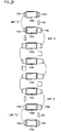
- the flat-type cells are arranged as shown in Fig. 19 , and laminated as shown in Fig. 20 . Specifically, from the top to the bottom, the flat-type cells 50A, 50B, 50C, 50A, 50B, 50C, 50A, and 50B shown in Fig. 17 , are laminated in order.
- units are produced in advance by combining the flat-type cells themselves indicated by the dotted line in Fig. 19 , and by ultrasonic welding the prescribed electrode tabs themselves. Namely, as shown in Fig. 19 , the unit “a” composed of the combination of the flat-type cells 50A and 50B, and the unit “b” and the unit “c” composed of the combination of the flat-type cells 50C, 50A and 50B, totally 3 units, are produced in advance.
- the electrode tabs connected by the dotted line shown in Figs. 19 and 20 are welded themselves with the ultrasonic welding machine 200 shown in Fig. 2 .
- the ultrasonic welding machine 200 shown in Fig. 2 For example, in Fig. 19 , in the case of producing the unit "a" composed of the combination of the flat-type cells 50A and 50B, first the protruding part 54B of the plus side electrode tab 52B of the flat-type cell 50B located at the lower part, and the protruding part 53A of the minus side electrode tab 51A of the flat-type cell 50A located upper next are welded.
- the insulating body 40 As an insulation means with a prescribed shape, is made present between the electrode tab 52A and the electrode tab 51B.
- the insulating body 40 a sheet-like one can be accepted or an insulating tape can be bonded on the lower surface (in the direction in the Figure) of the electrode tab 52A as well.
- the insulating body 40 with a prescribed shape is also made present inter-the electrode tabs 51A and 52C of the flat-type cells 50A and 50C composed of the unit "b" and the unit "c", and inter-the electrode tabs 52A and 51B of the flat-type cells 50A and 50B.
- the unit ⁇ (the second unit) is produced by welding the unit “a” and the unit “b” as shown in Fig. 20 .
- welding of the unit “a” and the unit “b” is performed by welding the protruding part 53B of the electrode tab 51B of the flat-type cell 50B located at the bottom of the unit "a", and the protruding part 54C of the electrode tab 52C of the flat-type cell 50C located at the top of the unit "b".
- the insulating body 40 is made present inter-the electrode tabs for preventing electrical connection between electrode tabs (52B and 51C) of the side not to be welded.
- the combined battery according to the present Embodiment is produced by welding the unit ⁇ and the unit "c". Welding of the unit ⁇ and the unit “c” is performed, as shown in Fig. 20 , by welding the protruding part 53B of the electrode tab 51B of the flat-type cell 50B located at the bottom of the unit ⁇ , and the protruding part 54C of the electrode tab 52C of the flat-type cell 50C located at the top of the unit "c".
- welding of the unit ⁇ and the unit "c" is performed as above, because the protruding parts to be object of welding are located at the positions not interrupted at all by other parts, welding operation is easy.
- the combined battery according to the present Embodiment is formed by producing the units “a”, “b”, and “c", then producing the unit ⁇ by welding the units “a” and “b”, and producing the combined battery by welding the units ⁇ and the unit “c", and because welding of all the units is performed at the positions not interrupted by other electrode tabs, welding operation is easy. Accordingly, freedom of the head shape of the ultrasonic welding machine becomes greater and automation of welding operation becomes easy. In addition, because ultrasound is used for welding and no mechanical bonding part is present, generation of contact resistance variation or loosening due to vibration is unlikely, and thus sufficient reliability can be kept in endurance-reliability and maintainability.
- the flat-type cells with the electrode tab shape as shown in Fig. 21 may be laminated.
- the positions of the protruding parts of the electrode tabs of the flat-type cells shown in Fig. 21 are all inverted of those shown in Fig. 20 . That is, in the flat-type cell 50a, the position of the protruding part thereof is exactly opposite of that in the flat-type cell 50A shown in Fig. 17 , and similarly in the flat-type cells 50b and 50c, the positions of the protruding parts thereof are exactly opposite of those in the flat-type cells 50B and 50C. Even if the flat-type cells 50a to 50c are used, the combined battery can easily be produced by welding while producing the units in order, in the same steps as the producing steps shown in Fig. 20 .
- a combined battery according to the present Embodiment is one formed by laminating 8 sheets of flat-type cells in the thickness direction thereof in the prescribed combination of the flat-type cells having 4 types of electrode tab shapes as shown in Fig. 22 .
- Each one of electrode tabs pulled out from both sides of the flat-type cells has a specific shape in each lamination layer position thereof so that welding positions are different when 8 sheets of the flat-type cells are laminated in order.
- the electrode tabs of the flat-type cells are electrically connected in series by welding with the ultrasonic welding machine 200 shown in Fig. 2 .
- the electrode tabs of the combined battery are arranged so that the protruding parts thereof are separated into 4 directions in the same way as Fig. 8 shown in Embodiment 2 in completely assembled state. In the combined battery, all of the 8 sheets of flat-type cells are electrically connected in series, in completely assembled state.
- the combined battery according to the present Embodiment makes the shapes of the electrode tab of each of flat-type cells different according to the position of lamination layer so that welding parts of the electrode tabs are separated into 4 directions.
- Fig. 22 shows the types of flat-type cells (electrode tab shapes are different) required for constructing the combined battery according to the present Embodiment. While the combined battery is composed of 8 laminated sheets of flat-type cells, the flat-type cells having 4 types of electrode tab shapes as shown in the figure, are used to separate the welding positions of the electrode tabs into 4 directions in the present Embodiment.
- the A type flat-type cell 60A has the minus side electrode tab 61A and the plus side electrode tab 62A, cut off both at the right side as viewed from each of the ends thereof, and has the protruding parts 63A and 64A at the left side as viewed from each of the ends thereof.
- the B type flat-type cell 60B has the minus side electrode tab 61B cut off at the right side as viewed from the end thereof, and the plus side electrode tab 62B cut off at the left side as viewed from the end thereof, and has the protruding part 63B at the left side as viewed from the end thereof and the protruding part 63 B at the right side.
- the C type flat-type cell 60C has the minus side electrode tab 61C cut off at the left side as viewed from the end thereof, and the plus side electrode tab 62C cut off at the right side as viewed from the end thereof, and has the protruding part 63C at the right side and the protruding part 64C at the left side.
- the D type flat-type cell 60D has the minus side electrode tab 61D cut off at the left side as viewed from the end thereof, and the plus side electrode tab 62D cut off at the left side as viewed from the end thereof, and has the protruding parts 63D and 64D at the right side as viewed from each of the ends thereof.
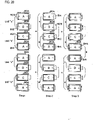
- the flat-type cells are arranged and laminated as shown in Fig. 23 . Specifically, from the top to the bottom, the flat-type cells 60A, 60A, 60B, 60C, 60A, 60B, 60D, and 60C shown in Fig. 22 are laminated in order.
- units are produced in advance by combining the flat-type cells themselves indicated by V-mark in Fig. 23 , and by ultrasonic welding the prescribed electrode tabs themselves. Namely, as shown in Fig. 23 , the unit “a” composed of a combination of the flat-type cells 60A and 60B, and the unit “b” composed of a combination of the flat-type cells 60C, 60A and 60B, and the unit “c” composed of a combination of the flat-type cells 60D and 60C, totally 3 units, are produced in advance. Naturally, similarly as in Embodiments 1 to 3, the insulating body is made present inter-the flat-type cells requiring insulation when these units are produced.
- the electrode tabs connected by the V-mark shown in Fig. 23 are welded themselves with the ultrasonic welding machine 200 shown in Fig. 2 . Because the specific method for the welding is the same as in the above-described Embodiments 1 to 3, the detailed explanation thereof is omitted. When each of the units is produced, because welding can be performed at entirely different positions, welding operation is easy.
- the insulating body is made present inter-the flat-type cells requiring insulation when such welding is performed.
- welding of the units is performed as above, because the protruding parts to be object of welding are located at the positions not interrupted at all by other parts, welding operation is easy.
- the combined battery according to the present Embodiment is formed by producing the units “a”, “b” and “c", then welding the flat-type cell 60A and the unit “a”, welding the units “a” and “b”, and further welding the unit “b” and the unit “c” so as to form the combined battery, and because welding of all the units is performed at the positions not interrupted by other electrode tabs, welding operation is easy. Accordingly, freedom of the head shape of the ultrasonic welding machine becomes greater and automation of welding operation becomes easy. In addition, because ultrasound is used for welding and no mechanical bonding part is present, generation of contact resistance variation or loosening due to vibration is unlikely, and thus sufficient reliability can be kept in endurance-reliability and maintainability.
- a combined battery according to the present Embodiment is one formed by laminating 8 sheets of flat-type cells in the thickness direction thereof in the prescribed combination of 6 types of the flat-type cells having a combination of different length of the electrode tabs as shown in Fig. 24 .
- Each one of the electrode tabs pulled out from both sides of the flat-type cell has a specific length in each lamination layer position thereof so that welding positions are different each other when 8 sheets of the flat-type cells are laminated in order.
- the electrode tabs of the flat-type cells are electrically connected in series by welding with the ultrasonic welding machine 200 shown in Fig. 2 .
- the electrode tabs of the combined battery are separated into 3 types in length so that the welding can be performed in order, from a short one to a long one during assembling process.
- all of the 8 sheets of flat-type cells are electrically connected in series in completely assembled state.
- the combined battery according to the present Embodiment makes the combination of electrode tab length of each of flat-type cells, different according to the position of lamination layer so that welding parts of the electrode tabs are separated into 3 positions in the length direction.
- Fig. 24 shows the types of the flat-type cells (electrode tab length are different) required for constructing the combined battery according to the present Embodiment. While the combined battery is composed of 8 laminated sheets of the flat-type cells, 6 types of the flat-type cells with a combination of different length as shown in the Figure are used to separate the welding positions of the electrode tabs into 3 places in the length direction in the present Embodiment.
- the length of the minus side electrode tab 71A and the plus side electrode tab 72A are made shorter than that of other flat-type cells.
- the B type flat-type cell 70B has the length of the minus side electrode tab 71B being the same as that of the minus side electrode tab 71A of the A type, and the length of the plus side electrode tab 72B longer than that of the plus side electrode tab 72A of the A type.
- the C type flat-type cell 70C has the length of the minus side electrode tab 71C being the same as that of the plus side electrode tab 72B of the B type, and the length of the plus side electrode tab 72C being the same as that of the minus side electrode tab 71B of the B type.
- the length of the minus side electrode tab 71D and the plus side electrode tab 72D of the D type are the same as that of the plus side electrode tab 72B of the B type.
- the length of the minus side electrode tab 71E of the E type is the same as that of the plus side electrode tab 72B of the B type and the plus side electrode tab 72E is longer than that of the electrode tabs of any other types.
- the F type flat-type cell 70F has the length of the minus side electrode tab 71F being the same as that of the plus side electrode tab 72E of the E type and the length of the plus side electrode tab 72F being the same as that of the plus side electrode tab 72B of the B type.
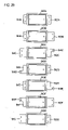
- the flat-type cells are arranged as shown in Fig. 25 , and laminated as shown in Fig. 26 . Specifically, from the top to the bottom, the flat-type cells 70A, 70C, 70D, 70F, 70E, 70C, 70B, and 70A shown in Fig. 24 are laminated in order.
- units are produced in advance by combining the flat-type cells themselves indicated by the dotted line in Fig. 25 , and by ultrasonic welding the prescribed electrode tabs themselves. Namely, as shown in Fig. 25 , the unit “a” composed of a combination of the flat-type cells 70A and 70C with the shortest electrode tab, and the unit “b” composed of a combination of the flat-type cells 70B and 70A, totally 2 units, are produced in advance.
- the electrode tabs connected by the dotted line shown in Figs. 25 and 26 are welded themselves with the ultrasonic welding machine 200 shown in Fig. 2 .
- the ultrasonic welding machine 200 shown in Fig. 2 in the case of producing the unit "a" composed of a combination of the flat-type cells 70A and 70C, the minus side electrode tab 71A of the flat-type cell 70A, and the plus side electrode tab 72C of the flat-type cell 70C, are welded.
- the unit "b" composed of a combination of the flat-type cells 70B and 70A, the minus side electrode tab 71B of the flat-type cell 70B, and the plus side electrode tab 72A of the flat-type cell 70A, are welded.
- welding is performed in order described above, welding operation is easy.
- the insulating body 40 As an insulation means with a prescribed shape, is made present between the electrode tab 72A and the electrode tab 71C.
- the insulating body 40 a sheet-like one can be accepted or an insulating tape can be bonded on the lower surface (in the direction in the Figure) of the electrode tab 72A as well.
- the insulating body 40 with a prescribed shape is also made present inter-the electrode tabs 72B and 71A of the flat-type cells 70B and 70A composed of the unit "b".
- the unit ⁇ and the unit ⁇ are produced by welding the flat-type cell 70D to the unit "a", and welding the flat-type cell 70C to the unit "b" as shown in Fig. 25 and Fig. 26 .
- welding of the unit "a” and the flat-type cell 70D for producing the unit ⁇ is performed by welding the electrode tab 71C of the flat-type cell 70C located at the bottom of the unit "a", and the electrode tab 72D of the flat-type cell 70D.
- the insulating body 40 is made present inter-the electrode tabs for preventing electrical connection between electrode tabs (72C and 71D) of the side not to be welded.
- welding of the unit "a” and the flat-type cell 70D is performed as above, because the length of the plus side electrode tab 72A of the flat-type cell 70A, is shorter than that of the minus side electrode tab 71C of the flat-type cell 70C, welding of the electrode tab 71C and the electrode tab 72D can be performed without touching the electrode tab 72A.
- the unit X and the unit Y are produced by welding the flat-type cell 70F to the unit ⁇ , and welding the flat-type cell 70E to the unit ⁇ .
- welding of the unit ⁇ and the flat-type cell 70F for producing the unit X is performed by welding the electrode tab 71D of the flat-type cell 70D located at the bottom of the unit ⁇ , and the electrode tab 71F of the flat-type cell 70F.
- the insulating body 40 is made present inter-the electrode tabs for preventing electrical connection between electrode tabs (72D and 71F) of the side not to be welded.
- welding of the unit ⁇ and the flat-type cell 70F is performed as above, because the length of the electrode tab 71D and the electrode tab 72F are longer than those of the electrode tabs 71A and 72C, welding of the electrode tab 71D and the electrode tab 72F can be performed without touching the electrode tab 71A and 72C of the flat-type cells 70A and 70C constructing the unit ⁇ . In addition, for the same reason, welding of the electrode tab 72C of the flat-type cell 70C constructing the unit ⁇ , and the electrode tab 71E of the flat-type cell 70E, can be performed as well without being disturbed in any way by other electrode tabs (71B and 72A).
- the combined battery according to the present Embodiment is produced by welding the unit X and the unit Y. Welding of the unit X and the unit Y is performed, as shown in Fig. 26 , by welding the electrode tab 71F of the flat-type cell 70F located at the bottom of the unit X, and the electrode tab 72E of the flat-type cell 70E located at the top of the unit Y. Because length of the electrode tab 70F and electrode tab 70E is made longer than that of any other electrode tabs, the welding can be performed without being disturbed by other electrode tabs, and welding operation is easy.
- the combined battery according to the present Embodiment is formed by producing the units “a” and "b", next producing the units ⁇ and ⁇ , finally welding the units X and Y, and because welding of all the units is performed at the positions not interrupted by other electrode tabs, welding operation is easy. Accordingly, freedom of the head shape of the ultrasonic welding machine becomes greater and automation of welding operation becomes easy. In addition, because ultrasound is used for welding and no mechanical bonding part is present, generation of contact resistance variation or loosening due to vibration occurs is unlikely, and thus sufficient reliability can be kept in endurance-reliability and maintainability.
- a combined battery according to the present Embodiment is one formed by laminating 8 sheets of flat-type cells in the thickness direction thereof in the prescribed combination of 3 types of the flat-type cells having a combination of different length of the electrode tabs as shown in Fig. 27 .
- Each one of the electrode tabs pulled out from both sides of the flat-type cell has a specific shape in each lamination layer position thereof so that welding positions are different each other when 8 sheets of the flat-type cells are laminated in order.
- the electrode tabs of the flat-type cells are electrically connected in series by welding with the ultrasonic welding machine 200 shown in Fig. 2 .
- the electrode tabs of the combined battery are separated into 2 types in length so that the welding can be performed in order, from the short to the long, during assembling process.
- all of the 8 sheets of flat-type cells are electrically connected in series in completely assembled state.
- the combined battery according to the present Embodiment makes the combination of electrode tab length of each of flat-type cells, different according to the position of lamination layer so that welding parts of the electrode tabs are separated into 2 places in the length direction.
- Fig. 27 shows the types of flat-type cells (electrode tabs are different in length) required for constructing the combined battery according to the present Embodiment. While the combined battery is composed of 8 laminated sheets of flat-type cells, the 3 types of flat-type cells with a combination of different length as shown in the Figure are used to separate the welding positions of the electrode tabs into 2 places in the length direction in the present Embodiment.
- the length of the minus side electrode tab 81A and the plus side electrode tab 82A are made shortest compared with other types of flat-type cells.
- the B type flat-type cell 80B has the length of the minus side electrode tab 81B, being the same as that of the plus side electrode tab 82A of the A type, and the length of the plus side electrode tab 82B, longer than that of the plus side electrode tab 81A and the minus side electrode tab 82A of the A type.
- the C type flat-type cell 80C has the length of the minus side electrode tab 81C, being the same as that of the plus side electrode tab 82B of the B type, and the length of the plus side electrode tab 82C, being the same as that of the minus side electrode tab 81B of the B type.
- the flat-type cells are arranged and laminated as shown in Fig. 28 . Specifically, from the top to the bottom, the flat-type cells 80A, 80B, 80C, 80A, 80A, 80B, 80C and 80A shown in Fig. 27 are laminated in order.
- units are produced in advance by combining the flat-type cells themselves indicated by the solid line in Fig. 28 , and by ultrasonic welding the prescribed electrode tabs themselves. Namely, as shown in step 1 in Fig. 28 , the unit “a” composed of a combination of the flat-type cells 80A and 80B, and the unit “b” composed of a combination of the flat-type cells 80C and 80A, and the unit “c” composed of a combination of the flat-type cells 80A and 80B, and the unit “d” composed of a combination of the flat-type cells 80C and 80A, totally 4 units, are produced in advance.
- the electrode tabs connected by the solid line shown in Fig. 28 are welded themselves with the ultrasonic welding machine 200 shown in Fig. 2 .
- the ultrasonic welding machine 200 shown in Fig. 2 For example, in Fig. 28 , in the case of producing the units "a" and "c" composed of a combination of the flat-type cells 80A and 80B, the plus side electrode tab 82A of the flat-type cell 80A and the minus side electrode tab 81B of the flat-type cell 80B are welded.
- the insulating body is made present inter-the electrode tabs of the side where welding is not performed.
- the unit “e” and the unit “f” are produced by welding both the unit “a” and the unit “b”, and the unit “c” and the unit “d” as shown in the step 2 in Fig. 28 .
- welding both the unit “a” and the unit “b”, and the unit “c” and the unit “d” are performed by welding the electrode tab 82B of the flat-type cell 80B located at the lower part of the units “a” and “C”, and the electrode tab 81C of the flat-type cell 80C located at the upper part of the units "b” and "d".
- the insulating body not shown in the Figure is made present inter-the electrode tabs to prevent short-circuit between the electrode tabs of the side where welding is not performed.
- the combined battery according to the present Embodiment is produced by welding the unit “e” and the unit “f”.
- the combined battery according to the present Embodiment is formed by producing the units “a”, “b", “c” and “d”, then producing the units “e” and “f”, and finally welding the units “e” and "f", and because welding up to the units “e” and "f", is performed at the positions not interrupted by other electrode tabs, welding operation is easy.
- a combined battery according to the present Embodiment is one formed by laminating 8 sheets of flat-type cells in the thickness direction thereof in the prescribed combination of the flat-type cells with 7 different shapes of the electrode tabs as shown in Fig. 29 .
- Each one of the electrode tabs pulled out from both sides of the flat-type cell has a specific shape and length thereof in each lamination layer position thereof so that welding positions are different each other when 8 sheets of the flat-type cells are laminated in order.
- the electrode tabs of the flat-type cells are electrically connected in series by welding with the ultrasonic welding machine 200 shown in Fig. 2 .
- the protruding parts thereof are made separated in 2 directions in assembled state.
- all of the 8 sheets of the flat-type cells are electrically connected in series, in assembled state.
- the combined battery according to the present Embodiment makes the position of the electrode tabs separated into 2 directions so that the welding positions of the electrode tabs do not overlap, and makes the shape and the length of the electrode tabs of each of the flat-type cells different according to the position of lamination layer in order to make the welding positions of the electrode tabs different in the length direction of the cell.
- Fig. 29 shows the types of flat-type cells (the electrode tab shapes are different) required for constructing the combined battery according to the present Embodiment.
- the combined battery is constructed by laminating 8 sheets of the flat-type cells
- the flat-type cells with the electrode tabs having 7 types of shapes of the electrode tabs as shown in the Figure are used to make welding positions of the electrode tabs dispersed into 4 places in the present Embodiment.
- the lengths of the minus side electrode tab 91A and the plus side electrode tab 92A are made shorter compared with other types of the flat-type cells.
- the B type flat-type cell 90B has the minus side electrode tab 91B with the same length as that of the minus side electrode tab 91A of the A type, and the plus side electrode tab 92B with the length longer than that of the plus side electrode tab 92A of the A type.
- the C type flat-type cell 90C has the minus side electrode tab 91C and the plus side electrode tab 92C with the same length as that of the plus side electrode tab 92B of the B type, a part of the plus side electrode tab 92C is cut off, and the protruding part 94C is formed.
- the D type flat-type cell 90D has the minus side electrode tab 91D with the same length as that of the plus side electrode tab 92B of the B type, and the plus side electrode tab 92D with the same length as that of the minus side electrode tab 91B of the B type, a part of the minus side electrode tab 91D is cut off, and the protruding part 93D is formed.
- the E type flat-type cell 90E has the plus side electrode tab 92E with the same length as that of the plus side electrode tab 92B of the B type, and the minus side electrode tab 91E with the same length as that of the minus side electrode tab 91B of the B type, a part of the plus side electrode tab 92E is cut off, and the protruding part 94E is formed.
- the F type flat-type cell 90F has the minus side electrode tab 91F and the plus side electrode tab 92F with the same length as that of the plus side electrode tab 92B of the B type, a part of the minus side electrode tab 91F is cut off, and the protruding part 93F is formed.
- the G type flat-type cell 90G has the plus side electrode tab 91G with the same length as that of the minus side electrode tab 91A of the A type, and the minus side electrode tab 91G with the same length as that of the plus side electrode tab 92B of the B type.
- the flat-type cells are arranged as shown in Fig. 30 , and laminated as shown in Fig. 31 . Specifically, from the top to the bottom, the flat-type cells 90A, 90G, 90F, 90E, 90D, 90C, 90B and 90A shown in Fig. 17 are laminated in order.
- units are produced in advance by combining the flat-type cells themselves indicated by the dotted line in Fig. 30 , and by ultrasonic welding the prescribed electrode tabs themselves. Namely, as shown in Fig. 30 , the unit “a” composed of the combination of the flat-type cells 90A, 90G and 90F, and the unit “b” composed of a combination of the flat-type cells 90E and 90D, and the unit “c” composed of a combination of the flat-type cells 90C, 90B and 90A, totally 3 units, are produced in advance.
- the electrode tabs connected by the dotted line shown in Fig. 30 and Fig. 31 are welded themselves with the ultrasonic welding machine 200 shown in Fig. 2 .
- Fig. 30 in the case of producing the unit "a" of a combination of the flat-type cells 90A, 90G and 90F, first the plus side electrode tab 92F of the flat-type cell 90F located at the lowest part and the minus side electrode tab 91G of the flat-type cell 90G located upper next, are welded. Next the plus side electrode tab 92G of the flat-type cell 90G and the minus side electrode tab 91A of the flat-type cell 90A, are welded.
- the plus side electrode tab 92D of the flat-type cell 90D and the minus side electrode tab 91E of the flat-type cell 90E located upper next are welded.
- the plus side electrode tab 92A of the flat-type cell 90A located at the lowest part and the minus side electrode tab 91B of the flat-type cell 90B located upper next are welded.
- the plus side electrode tab 92B of the flat-type cell 90B and the minus side electrode tab 91C of the flat-type cell 90C located upper next are welded.
- the insulating body 40 is made present as shown in the figure between the electrode tabs of the side not to be welded. As the insulating body 40, a sheet-like one can be accepted, or an insulating tape can be bonded on the lower surface (in the direction in the figure) of the electrode tab as well.
- the combined battery according to the present Embodiment is produced by welding the units “a", “b” and “c".
- Welding of the unit “a” and the unit “b” is performed by welding the protruding part 93F of the minus side electrode tab 91F of the flat-type cell 90F located at the bottom of the unit “a”, and the protruding part 94E of the plus side electrode tab 92E of the flat-type cell 90E located at the upper part of the unit "b”, and welding of the unit “b” and the unit “c”, is performed by welding the protruding part 93D of the minus side electrode tab 91D of the flat-type cell 90D located at the lower part of the unit "b", and the protruding part 94C of the plus side electrode tab 92C of the flat-type cell 90C located at the top of the unit "c”.
- the insulating body 40 is made present as shown in the Figure inter-the electrode tabs of the side not to be welded.
- the units "a", “b”, and “c” as above, because the protruding part 93F of the electrode tab 91F and the protruding part 94E of the electrode tab 92E, to be welded each other, are protruding from the electrode tabs 91A and 92G, and the protruding part 93D of the electrode tab 91D, and the protruding part 94C of the electrode tab 92C, to be welded each other, are protruding from the electrode tabs 91B and 92A, and further the welding position between the protruding part 93F and the protruding part 94E is different from the welding position between the protruding part 93D and the protruding part 94C, welding can be performed without being interrupted in any way by other electrode tabs.
- the combined battery according to the present Embodiment is formed by producing the units “a”, “b” and “c", and, then by welding these units, and because welding of each of the units is performed at the positions not interrupted by other electrode tabs, welding operation is easy. Accordingly freedom of the head shape of the ultrasonic welding machine becomes greater and automation of welding operation becomes easy. In addition, because ultrasound is used for welding and no mechanical bonding part is present, generation of contact resistance variation or loosening due to vibration is unlikely, and thus sufficient reliability can be kept in endurance-reliability and maintainability.
- a combined battery according to the present Embodiment is one formed by laminating 8 sheets of flat-type cells in the thickness direction thereof in the prescribed combination thereof with 6 different positions where the electrode tabs thereof are pulled out, as shown in Fig. 32 .
- Each one of the electrode tabs pulled out from the flat-type cell has different positions to be pulled out so that welding positions are different each other when 8 sheets of the flat-type cells are welded in order.
- the electrode tabs of the flat-type cells are electrically connected in series by welding with the ultrasonic welding machine 200 shown in Fig. 2 .
- the protruding parts thereof are made separated in 4 directions in assembled state.
- all of the 8 sheets of the flat-type cells are electrically connected in series, in assembled state.
- the combined battery according to the present Embodiment makes the position of the flat-type cell where the electrode tabs are pulled out, different according to the position of lamination layer so as to separate the welding positions of the electrode tabs into 4 directions.
- Fig. 32 shows the types of flat-type cells (the positions where the electrode tabs are pulled out are different) required for constructing the combined battery according to the present Embodiment. While the combined battery is composed of 8 laminated sheets of the flat-type cells, the flat-type cells with the electrode tabs having 6 types of the positions where the electrode tabs are pulled out as shown in the Figure, are used to separate welding positions of the electrode tabs into 4 directions in the present Embodiment.
- the minus side electrode tabs 97A and 97H, and the plus side electrode tabs 96A and 96H are pulled out from the both ends of the flat-type cells 95A and 95H.
- the minus side electrode tabs 97B, 97 C, 97F, and 97G, and the plus side electrode tabs 96B, 96C, 96F, and 96G are pulled out with being adjacent to each other thereof.
- the minus side electrode tabs 97D and 97E and the plus side electrode tabs 96D and 96E are pulled out with having a certain distance therebetween.
- the unit “a” is produced by welding the plus side electrode tab 96A of the flat-type cell 95A, and the minus side electrode tab 97B of the flat-type cell 95B
- the unit “b” is produced by welding the plus side electrode tab 96C of the flat-type cell 95C, and the minus side electrode tab 97D of the flat-type cell 95D
- the unit “c” is produced by welding the plus side electrode tab 96E of the flat-type cell 95E, and the minus side electrode tab 97F of the flat-type cell 95F
- the unit “d” is produced by welding the plus side electrode tab 96G of the flat-type cell 95G and the minus side electrode tab 97H of the flat-type cell 95H.
- the units "a” and “b” are laminated and the plus side electrode tab 96B of the flat-type cell 95B and the minus side electrode tab 97C of the flat-type cell 95C, are welded. At this time, an insulating body is made present between the minus side electrode tab 97B of the flat-type cell 95B, and the plus side electrode tab 96C of the flat-type cell 95C.
- the units "c” and “d” are laminated and the plus side electrode tab 96F of the flat-type cell 95F, and the minus side electrode tab 97G of the flat-type cell 95G are welded. At this time, an insulating body is made present between the minus side electrode tab 97F of the flat-type cell 95F, and the plus side electrode tab 96G of the flat-type cell 95G.
- the units "a” to “d” are laminated by welding the plus side electrode tab 96D of the flat-type cell 95D and the minus side electrode tab 97E of the flat-type cell 95E.
- an insulating body is made present between the minus side electrode tab 97C of the flat-type cell 95C, and the plus side electrode tab 96F of the flat-type cell 95F.
- an insulating body it is the same as in Embodiments 1 to 3 for an insulating body to be made present inter-the electrode tabs requiring insulation.
- the combined battery according to the present Embodiment is formed by producing the units “a”, “b”, “c” and “d”, and next welding the unit “a” and the unit “b”, further welding the unit “c” and the unit “d”, and finally welding all the units, and because welding of each of the units is performed at the positions not interrupted by other electrode tabs, welding operation is easy. Accordingly freedom of the head shape of the ultrasonic welding machine becomes greater and automation of welding operation becomes easy. In addition, because ultrasound is used for welding and no mechanical bonding part is present, generation of contact resistance variation or loosening due to vibration is unlikely, and thus sufficient reliability can be kept in endurance-reliability and maintainability.
- a combined battery according to the present Embodiment is one formed by laminating 16 sheets of flat-type cells in the thickness direction thereof with a circular shape, and arranged to have specified central angle so that the plus side electrode tab and the minus side electrode tab are connected as shown in Fig. 33 .
- the combined battery 400 according to the present Embodiment has a circular shape viewed from the lamination direction, and the plus side electrode tab 410A is arranged to have a central angle of 157.5 degree relative to the minus side electrode tab 410B so as to be off set from diameter with the electrode tab 410B as a base point.
- the flat-type cells 400 having the electrode tabs with the positional relation being off set with each other thereof as described, are laminated by overlapping the plus side electrode tab and the minus side electrode tab thereof in the lamination direction.
- Fig. 34 shows the state of arrangement of the electrode tabs, when 3 sheets of the flat-type cells are laminated.
- the minus side electrode tab 410D of the flat-type cell 400 to be laminated thereon is overlapped, and on the plus side electrode tab 410C of the flat-type cell 400 laminated, the minus side electrode tab 410F of the flat-type cell 400 to be laminated thereon, is overlapped.
- the electrode tabs come to protrude from evenly separated 16 different places of the peripheral part of the flat-type cells. In this state, the electrode tabs at 14 places except the electrode tabs at two places to take out voltage, are welded by the ultrasonic welding machine 200 shown in Fig. 2 .
- welding In the case of welding, welding of the electrode tabs themselves to compose the combined battery is performed while positioning a welding jig and the electrode tabs in the direction of the periphery of the cells, along with vertically positioning the welding jig. In this way, all of the flat-type cells 400 are connected in series.
- the combined battery unit 450 is formed by further laminating a plurality (for example, 6 stages) of the combined batteries formed as described, and is fixed by being sandwiched from both sides by the cases 420A and 420B divided in 2 parts as shown in Fig. 35 and Fig. 36 . While the welded electrode tabs 410 are protruding from the periphery of the assembled battery unit 450, because the connectors 430, with the number thereof corresponding to that of the electrode tabs, are mounted at the positions corresponding to the electrode tabs, in the cases 420A and 420B, all the electrode tabs 410 are designed to fit neatly in the connectors when the cases 420A and 420B are assembled with the combined battery unit 450.
- the connectors are equipped with to detect voltage of each of the flat-type cells 400, and the signal wires 435 are connected to all the connectors, and voltage of each of the flat-type cells can be detected from outside.
- the connectors 430 are mounted in the cases 420A and 420B in this way, wiring operation of the signal wires to detect voltage becomes unnecessary and therefore efficiency of assembling operation can considerably be enhanced.
- the thread 465 is formed at the upper part of the cases 420A and 420B, to mount the compression cap 460 so as to apply surface pressure in the lamination direction on all the flat-type cells 400.
- the combined battery unit 450 is set into the cases 420A and 420B, and the compression cap 460 is mounted by screwing the thread of the compression cap 460 to the thread 465 as shown in Fig. 38 .
- the compression cap 460 is getting fastened by screwing, surface pressure in the lamination direction is added on the flat-type cells 400 as shown in the Figure. When the surface pressure is kept added in this way, the lifetime of the combined battery unit 450 can be extended.
- the compression force applied by the compression cap 460 becomes approximately 120 Kgf in the case of the present Embodiment.
- the cooling case 480 is mounted as shown in Fig. 39 and Fig. 40 , to make cooling air pass through the combined battery unit 450.
- the spacer 470 for cooling is made present therebetween.
- a lot of through-passages capable of making air pass through in one direction are formed inside.
- the air inlet hole 485 and the air outlet hole 490 are formed in the cooling case 480.
- Fig. 40(A) is a cross-sectional view of Fig. 39 along the line A-A, showing the positional relation of the cooling case 480 and the combined battery 400, and Fig.
- FIG. 40(B) is a cross-sectional view of Fig. 39 along the line B-B, showing the positional relation of the cooling case 480 and the spacer 470.
- the air inlet hole 485 and the air outlet hole 490 are independently formed at the positions shown in Fig. 40(B) . Therefore, as shown in Fig. 39 , when the combined battery unit 450 is inserted in the cooling case 480, and air is supplied to the air inlet hole 485, supplied air comes to the air outlet hole 490 through the through-passages of each of the spacers 470. Because both sides of the spacer 470 contact directly to the combined battery 400, the combined batteries are cooled by air supplied to the cooling case 480.
- Fig. 41 is a cross-sectional view of the battery according to the present Embodiment.
- the combined battery unit 450 set in the case 420 is received inside the cooling case 480.
- the combined battery unit 450 is formed by laminating 6 combined batteries with 5 spacers being made present therebetween.
- the connectors mounted in the case 420 are automatically united with the electrode tabs protruding from the peripheral of the combined batteries when the case is assembled.
- the case 420 is equipped with the compression cap 460, the flat-type cells constructing the combined battery are compressed with suitable pressure in the lamination direction. Because the air inlet hole 485 and the air outlet hole 490 are formed in the cooling case 480, air supplied from the air inlet hole 485 is exhausted from the air outlet hole 490 through all of the spacers 470 as shown in the Figure.
- Fig. 42 is an outline view of a combined battery according to Embodiment 10.
- the combined battery 500 according to the present Embodiment is one formed by laminating 8 sheets of flat-type cells in the thickness direction thereof so that polarity of electrode tabs is alternately set, and one formed by folding a series of the combined batteries with a plurality of flat-type cells sequentially connected in a form of a sheet.
- the combined battery 500 according to the present Embodiment has a construction, wherein all of the flat-type cells are electrically connected by welding the entire electrode tabs thereof, because the electrode tabs for welding the flat-type cells themselves in series are separated at a plurality of positions of the flat-type cells, when all of the flat-type cells are laminated. Specifically, as shown in Fig.
- the flat-type cells are rectangular in shape viewed from the top, and the welding parts of the electrode tabs are arranged so that the positions thereof become different in the shorter-length direction of the flat-type cells, when folding of a series of the flat-type cells (which is constructed by 8 sheets of the flat-type cells which are sequentially connected with adjacent sides themselves having no electrode tabs) which are sequentially connected in a form of a sheet, is finished. Therefore, the positions for the electrode tabs to be pulled out from both sides of all the flat-type cells composing the flat-type cells in a form of a sheet are different according to each lamination position thereof so that the electrode tabs to compose a set, are separated into 4 directions when 8 sheets of the flat-type cells are laminated. In the present Embodiment, 8 types of flat-type cells, with the electrode tabs pulled out at different positions, are used to separate the positions of the electrode tabs into 4 directions.
- the electrode tabs of the flat-type cells are electrically connected by welding with the ultrasonic welding machine 200 shown in Fig. 2 .
- the electrode tabs of the flat-type cells are arranged so that the protruding parts thereof are separated into 4 directions, as shown in Fig. 42 , in lamination finished state.
- 8 sheets of flat-type cells are all connected in series in completely assembled state.
- the flat-type cells in a form of a sheet are sequentially connected with adjacent sides themselves having no electrode tabs, as shown in Fig. 43 , and the electrode tabs are pulled out at the different positions from each of the cells.
- the plus side electrode tab 512A is pulled out from the upper-left end, in the Figure, of the flat-type cell 510A, and the minus side electrode tab 514A is pulled out differently from the lower-right end thereof.
- the plus side electrode tab 521B is pulled out from the lower-left end of the flat-type cell 510B, and the minus side electrode tab 514B is pulled out differently, at the upper-left side thereof, from the position shifted inward just by a little larger width than that of the electrode tab.
- the plus side electrode tabs 512C and 512G, and the minus side electrode tabs 514C and 514G are pulled out, respectively, at the positions shifted inward just by a little larger width than that of the electrode tab.
- the minus side electrode tab 514D is pulled out from the center thereof, and in the lower side thereof, the plus side electrode tab 512D is pulled out at the position shifted inward just by a little larger width than that of the electrode tab. From the centers of the upper side and the lower side of the flat-type cell 510E, the plus side electrode tab 512E and the minus side 514E are pulled out. In the lower side of the flat-type cell 510F, the plus side electrode tab 512F is pulled out from the center thereof, and in the upper side thereof, the minus side electrode tab 514F is pulled out at the position shifted inward just by a little larger width than that of the electrode tab.
- the minus side electrode tab 514H From the upper-left end of the flat-type cell 510H, the minus side electrode tab 514H, and at the lower-right side thereof, from the position shifted inward just by a little larger width than that of the electrode tab, the plus side electrode tab 514H are differently pulled out.
- the electrode tabs 514A and 512B overlap as a set
- the electrode tabs 514C and 512D overlap as a set
- the electrode tabs 514E and 512F overlap as a set
- the electrode tabs 512G and 512H overlap as a set
- the electrode tabs 514B and 512C overlap as a set
- the electrode tabs 514D and 512E overlap as a set
- the electrode tabs 514F and 512G overlap as a set.
- the flat-type cells in the overlapped state as shown in Fig. 42 is brought to the ultrasonic welding machine 200, and the electrode tabs to compose a set, are welded in order.
- the combined battery is produced by folding thereof in zigzags as shown in Fig. 44(a)
- the combined battery can be produced as well by winding thereof in a roll shape, similar to laminating, as shown in the figure (b).
Landscapes
- Chemical & Material Sciences (AREA)
- Chemical Kinetics & Catalysis (AREA)
- Electrochemistry (AREA)
- General Chemical & Material Sciences (AREA)
- Engineering & Computer Science (AREA)
- Manufacturing & Machinery (AREA)
- Connection Of Batteries Or Terminals (AREA)
- Battery Mounting, Suspending (AREA)
Claims (11)
- Batterie combinée comprenant une pluralité de cellules plates laminées et reliées électriquement ayant des languettes d'électrodes avec une polarité différente, comprenant :
une pluralité d'unités comprenant une pluralité de cellules plates laminées et reliées électriquement, dans laquelle :dans chacune des unités, une partie de soudage pour relier électriquement les cellules plates elles-mêmes est disloquée des languettes d'électrodes autres que deux languettes d'électrodes reliées électriquement par celle-ci, vues depuis la direction de laminage ; dans laquelleune partie de soudage pour relier électriquement les unités elles-mêmes est disloquée de toutes les languettes d'électrodes soudées à la formation des unités, vues depuis la direction de laminage, et dans laquelleles languettes d'électrodes des cellules plates sont laminées et directement reliées elles-mêmes en les soudant dans chaque groupe des languettes et chaque unité des cellules, et ainsi toutes les unités des cellules plates sont électriquement reliées en série, dans laquelleles languettes sont un seul L. - Batterie combinée selon la revendication 1, caractérisée en ce que :la forme des cellules plates est un rectangle, vu depuis la direction de laminage ; et dans laquelleune direction dans laquelle une position de la partie de soudage est disloquée est au moins l'une quelconque d'une direction de longueur plus courte et d'une direction de longueur des cellules plates.
- Batterie combinée selon la revendication 1, caractérisée en ce que :
chaque partie de soudage est disloquée de toutes les languettes d'électrodes autres que deux languettes d'électrodes reliées électriquement par celle-ci, vues depuis la direction de laminage. - Batterie combinée selon la revendication 1 ou 2, caractérisée en ce que :la forme des cellules plates est un rectangle, vu depuis la direction de laminage ; et dans laquelleune direction dans laquelle une position de la partie de soudage est disloquée est une direction de longueur plus courte des cellules plates.
- Batterie combinée selon la revendication 1 ou 2, caractérisée en ce que :la forme des cellules plates est une forme circulaire ou polygonale de pentagone ou plus, vus depuis la direction de laminage ; et dans laquelleles deux languettes d'électrodes reliées électriquement font saillie d'une position différente de la circonférence de la forme circulaire ou polygonale, de deux autres languettes d'électrodes reliées électriquement, vues depuis la direction de laminage.
- Procédé de fabrication d'une batterie combinée comprenant une pluralité de cellules plates laminées et reliées électriquement ayant des languettes d'électrodes de polarité différente, le procédé comprenantune première étape de formation d'une pluralité d'unités en reliant électriquement des cellules plates laminées ; etune deuxième étape de formation d'une batterie combinée en reliant électriquement des unités laminées ; dans lequel :
dans les première et deuxième étapes, chaque liaison électrique de la languette d'électrode d'une cellule plate et de la languette d'électrode de l'autre cellule plate est réalisée par une partie de soudage, qui est disloquée des languettes d'électrodes autres que deux languettes d'électrodes, c'est-à-dire que la languette d'électrode de la cellule plate et la languette d'électrode de l'autre cellule plate, vues depuis la direction de laminage, dans les cellules plates laminées dans la liaison électrique concernée, dans lequel les languettes d'électrodes des cellules plates sont laminées et directement reliées elles-mêmes en les soudant dans chaque groupe des languettes et chaque unité des cellules, et ainsi toutes les unités des cellules plates sont reliées électriquement en série, dans lequel les languettes sont un seul L. - Procédé de fabrication d'une batterie combinée selon la revendication 6, caractérisé en ce que :la forme des cellules plates est un rectangle, vu depuis la direction de laminage ; et dans lequelune direction dans laquelle une position de la partie de soudage est disloquée en liaison électrique est au moins l'une quelconque d'une direction de longueur plus courte et d'une direction de longueur des cellules plates.
- Procédé de fabrication d'une batterie combinée selon la revendication 6, caractérisé en ce que :
chaque partie de soudage pour relier électriquement les cellules plates elles-mêmes est disloquée de toutes les languettes d'électrodes autres que deux languettes d'électrodes reliées électriquement par celle-ci, vues depuis la direction de laminage, dans les cellules plates laminées dans la liaison électrique concernée. - Procédé de fabrication d'une batterie combinée selon la revendication 6 ou 8, caractérisé en ce que :la forme des cellules plates est un rectangle, vu depuis la direction de laminage ; et dans lequelune direction dans laquelle une position de la partie de soudage est disloquée est une direction de longueur plus courte des cellules plates.
- Procédé de fabrication d'une batterie combinée selon la revendication 6 ou 9, caractérisé en ce que, lors du laminage des cellules plates, des cellules plates sont laminées en pliant une série de cellules plates en zigzags, ou en les enroulant sous forme de rouleau.
- Procédé de fabrication d'une batterie combinée selon la revendication 6 ou 9, caractérisé en ce que :la forme des cellules plates est une forme circulaire ou polygonale de pentagone ou plus, vue depuis la direction de laminage ; et dans lequelpar laminage des cellules plates, les cellules plates sont laminés de sorte que deux languettes d'électrodes reliées électriquement fassent saillie d'une position différente de la circonférence de la forme circulaire ou polygonale, de deux autres languettes d'électrodes reliées électriquement, vues depuis la direction de laminage.
Applications Claiming Priority (4)
| Application Number | Priority Date | Filing Date | Title |
|---|---|---|---|
| JP2004161299 | 2004-05-31 | ||
| JP2004363123 | 2004-12-15 | ||
| JP2005068230A JP2006196428A (ja) | 2004-05-31 | 2005-03-10 | 組電池およびその製造方法 |
| PCT/JP2005/009904 WO2005117163A1 (fr) | 2004-05-31 | 2005-05-30 | Batterie assemblée et méthode de fabrication |
Publications (4)
| Publication Number | Publication Date |
|---|---|
| EP1770801A1 EP1770801A1 (fr) | 2007-04-04 |
| EP1770801A4 EP1770801A4 (fr) | 2009-06-03 |
| EP1770801B1 true EP1770801B1 (fr) | 2022-04-06 |
| EP1770801B8 EP1770801B8 (fr) | 2022-06-08 |
Family
ID=35451175
Family Applications (1)
| Application Number | Title | Priority Date | Filing Date |
|---|---|---|---|
| EP05743376.5A Expired - Lifetime EP1770801B8 (fr) | 2004-05-31 | 2005-05-30 | Batterie assemblée et méthode de fabrication |
Country Status (6)
| Country | Link |
|---|---|
| US (2) | US9246145B2 (fr) |
| EP (1) | EP1770801B8 (fr) |
| JP (1) | JP2006196428A (fr) |
| KR (1) | KR101012521B1 (fr) |
| CA (1) | CA2569013C (fr) |
| WO (1) | WO2005117163A1 (fr) |
Families Citing this family (58)
| Publication number | Priority date | Publication date | Assignee | Title |
|---|---|---|---|---|
| KR100895203B1 (ko) * | 2006-05-15 | 2009-05-06 | 주식회사 엘지화학 | 중대형 전지모듈 |
| JP5177989B2 (ja) * | 2006-10-17 | 2013-04-10 | 日産自動車株式会社 | 組電池の製造方法及び組電池 |
| KR101048226B1 (ko) * | 2007-01-25 | 2011-07-08 | 에스케이이노베이션 주식회사 | 리튬 이차 전지 |
| WO2008121892A1 (fr) * | 2007-03-31 | 2008-10-09 | Maxwell Technologies, Inc | Interface de borne de noyau d'électrode ondulée |
| US8865337B2 (en) * | 2008-03-24 | 2014-10-21 | Lightening Energy | Modular battery, an interconnector for such batteries and methods related to modular batteries |
| JP2010073571A (ja) * | 2008-09-19 | 2010-04-02 | Panasonic Corp | リチウムイオン二次電池およびその製造方法 |
| US8153290B2 (en) * | 2008-10-28 | 2012-04-10 | Tesla Motors, Inc. | Heat dissipation for large battery packs |
| DE102009006117A1 (de) * | 2009-01-26 | 2010-07-29 | Li-Tec Battery Gmbh | Elektrochemische Energiespeicherzelle |
| US8173294B2 (en) | 2009-04-28 | 2012-05-08 | Lightening Energy | High voltage modular battery with electrically-insulated cell module and interconnector peripheries |
| KR101139016B1 (ko) * | 2009-06-17 | 2012-04-26 | 주식회사 엘지화학 | 다방향성 리드-탭 구조를 가진 리튬 이차 전지 |
| JP5451315B2 (ja) * | 2009-10-28 | 2014-03-26 | Necエナジーデバイス株式会社 | 組電池 |
| JP5375558B2 (ja) * | 2009-11-27 | 2013-12-25 | トヨタ自動車株式会社 | 組電池及び組電池の製造方法 |
| DE102009056785A1 (de) * | 2009-12-03 | 2011-06-09 | Continental Automotive Gmbh | Batteriezelle sowie Batteriezellenanordnung aus elektrisch miteinander verbundenen Batteriezellen |
| DE102009058883B4 (de) | 2009-12-18 | 2020-06-25 | Continental Automotive Gmbh | Verfahren zum Verbinden von Zellableitern |
| US8822064B2 (en) * | 2009-12-31 | 2014-09-02 | Lightening Energy | Modular battery with polymeric compression sealing |
| US8343642B2 (en) | 2009-12-31 | 2013-01-01 | Lightening Energy | High voltage modular battery with compression bladder |
| US20110177383A1 (en) * | 2010-01-19 | 2011-07-21 | Lightening Energy | Battery cell module for modular battery with interleaving separator |
| US20110200867A1 (en) * | 2010-02-16 | 2011-08-18 | Lightening Energy | Modular battery with battery cell having bimetallic end plates |
| JP5589534B2 (ja) * | 2010-04-28 | 2014-09-17 | 日産自動車株式会社 | 扁平型電池 |
| KR101442432B1 (ko) | 2010-06-17 | 2014-09-17 | 닛산 지도우샤 가부시키가이샤 | 워크 위치 결정 장치 및 워크 제조 방법 |
| EP2500972B1 (fr) | 2010-12-20 | 2017-07-26 | LG Chem, Ltd. | Batterie secondaire au lithium ayant une structure à pattes conductrices multidirectionnelles |
| KR101243591B1 (ko) * | 2010-12-24 | 2013-03-20 | 삼성에스디아이 주식회사 | 전극 조립체 및 이를 포함하는 이차전지 |
| US8350526B2 (en) | 2011-07-25 | 2013-01-08 | Lightening Energy | Station for rapidly charging an electric vehicle battery |
| US9786961B2 (en) | 2011-07-25 | 2017-10-10 | Lightening Energy | Rapid charging electric vehicle and method and apparatus for rapid charging |
| US8174235B2 (en) | 2011-07-25 | 2012-05-08 | Lightening Energy | System and method for recharging electric vehicle batteries |
| US10110056B2 (en) | 2012-02-16 | 2018-10-23 | Lightening Energy | Energy banking system and method using rapidly rechargeable batteries |
| EP2804239B1 (fr) * | 2012-04-16 | 2017-09-27 | LG Chem, Ltd. | Ensemble d'électrodes présentant des formes différentes de partie de soudure d'anode et de cathode et batterie rechargeable le comprenant |
| JP6313227B2 (ja) * | 2012-04-16 | 2018-04-18 | エルジー・ケム・リミテッド | 互いに異なる形状の正極及び負極を含む電極組立体及び二次電池 |
| KR101924193B1 (ko) | 2012-06-20 | 2018-12-03 | 에스케이이노베이션 주식회사 | 배터리 모듈 용접 방법 및 용접구조 |
| KR102008740B1 (ko) * | 2012-10-05 | 2019-08-08 | 에스케이이노베이션 주식회사 | 전지팩 |
| KR101984314B1 (ko) * | 2012-12-26 | 2019-05-30 | 에스케이이노베이션 주식회사 | 이차전지 |
| KR101596266B1 (ko) * | 2013-03-05 | 2016-02-22 | 주식회사 엘지화학 | 다면체 전지셀 및 이를 포함하는 전지모듈 어셈블리 |
| JP6149629B2 (ja) * | 2013-09-13 | 2017-06-21 | 株式会社村田製作所 | 蓄電デバイスおよび蓄電デバイスモジュール |
| US9207153B2 (en) | 2013-09-30 | 2015-12-08 | Lg Chem, Ltd. | Test jig |
| KR101551534B1 (ko) * | 2013-09-30 | 2015-09-08 | 주식회사 엘지화학 | 테스트 지그 |
| KR101674264B1 (ko) * | 2014-01-28 | 2016-11-08 | 주식회사 엘지화학 | 전극조립체 및 그를 포함하는 전지셀 |
| US9172122B2 (en) | 2014-02-25 | 2015-10-27 | Lg Chem, Ltd. | Battery module |
| JP6504158B2 (ja) * | 2014-03-25 | 2019-04-24 | 日本電気株式会社 | 積層型電池及びその製造方法 |
| WO2016004079A1 (fr) | 2014-06-30 | 2016-01-07 | Black & Decker Inc. | Bloc-batterie pour des outils électriques sans fil |
| JP2017162546A (ja) * | 2014-07-22 | 2017-09-14 | 日産自動車株式会社 | 組電池の製造方法および製造装置 |
| US10062931B2 (en) | 2015-04-22 | 2018-08-28 | Johnson Controls Technology Company | Welding process for battery module components |
| CN108352469B (zh) * | 2015-10-22 | 2019-06-18 | 日产自动车株式会社 | 组电池 |
| KR102080284B1 (ko) * | 2015-10-22 | 2020-02-21 | 주식회사 엘지화학 | 복수의 전극 탭들이 형성되어 있는 단위 전극을 포함하는 파우치형 전지셀 |
| KR102125059B1 (ko) | 2016-06-07 | 2020-06-19 | 주식회사 엘지화학 | 상호 결합된 극판 연장부들이 형성되어 있는 극판들을 포함하고 있는 전극조립체 |
| KR102098096B1 (ko) | 2016-11-14 | 2020-04-07 | 주식회사 엘지화학 | 콤팩트한 결합 구조를 가지는 탭과 리드를 포함하는 전지셀 |
| KR102140311B1 (ko) * | 2017-04-07 | 2020-07-31 | 주식회사 엘지화학 | 배터리 모듈과 이를 포함하는 배터리 팩 및 자동차 |
| US10375830B2 (en) * | 2017-06-02 | 2019-08-06 | GM Global Technology Operations LLC | Method of assembling power module via folding |
| US11038192B2 (en) | 2017-06-02 | 2021-06-15 | GM Global Technology Operations LLC | Configurations for power module having an integrated flexible circuit assembly |
| KR20190047965A (ko) | 2017-10-30 | 2019-05-09 | 진우산전 주식회사 | 하이패스 단말을 이용한 주차 관제 시스템 |
| KR102597528B1 (ko) * | 2018-07-03 | 2023-11-01 | 에스케이온 주식회사 | 고전압 배터리 셀 |
| CN109560326B (zh) * | 2018-10-24 | 2021-07-20 | 湖南立方新能源科技有限责任公司 | 一种用于叠片工艺的重片检测方法 |
| JP6762445B1 (ja) * | 2019-03-29 | 2020-09-30 | 株式会社神戸製鋼所 | アルミニウム材のスポット溶接方法 |
| KR102124626B1 (ko) * | 2019-05-23 | 2020-06-19 | 에스케이이노베이션 주식회사 | 이차전지 |
| KR102866959B1 (ko) | 2020-01-13 | 2025-10-01 | 주식회사 엘지에너지솔루션 | 폴딩 구조를 적용한 파우치형 배터리 팩 및 그 제조 방법 |
| JP7463930B2 (ja) | 2020-09-30 | 2024-04-09 | トヨタ自動車株式会社 | 電池 |
| IT202000026593A1 (it) * | 2020-11-06 | 2022-05-06 | Ferrari Spa | Metodo di assemblaggio celle, unita' di accumulo e relativo pacco batteria veicolare |
| JPWO2024237140A1 (fr) * | 2023-05-12 | 2024-11-21 | ||
| FR3161070B1 (fr) * | 2024-04-09 | 2026-04-24 | Verkor | Cellules électrochimiques et modules de batterie intégrant de telles cellules |
Citations (3)
| Publication number | Priority date | Publication date | Assignee | Title |
|---|---|---|---|---|
| US20030113621A1 (en) * | 2001-12-13 | 2003-06-19 | Nissan Motor Co., Ltd. | Battery and assembled battery using the same |
| US20030224246A1 (en) * | 2002-06-03 | 2003-12-04 | Nissan Motor Co., Ltd. | Battery and related method |
| JP2004014317A (ja) * | 2002-06-07 | 2004-01-15 | Nissan Motor Co Ltd | 薄型電池の組電池 |
Family Cites Families (23)
| Publication number | Priority date | Publication date | Assignee | Title |
|---|---|---|---|---|
| GB2245412B (en) * | 1990-06-20 | 1995-01-25 | Dowty Electronic Components | Battery comprising interconnecting means of electrochemical cell units |
| DE69218587T2 (de) * | 1991-12-06 | 1997-08-14 | Yuasa Battery Co Ltd | Dünne batterie und monolitische dünne batterie |
| US5585206A (en) * | 1994-03-08 | 1996-12-17 | Morris; J. Lee | Battery electrode interconnections |
| JPH09147830A (ja) | 1995-11-24 | 1997-06-06 | Sony Corp | 電池及びその電極構造体 |
| JPH10106531A (ja) * | 1996-09-25 | 1998-04-24 | Asahi Chem Ind Co Ltd | パッケージ扁平型電池 |
| CN100336245C (zh) * | 1998-01-14 | 2007-09-05 | 杨泰和 | 储放电装置的低内阻汇流结构 |
| JP2002525823A (ja) * | 1998-09-24 | 2002-08-13 | トーマス アンド ベッツ インターナショナル,インク. | 電気化学電池の改良された製造方法 |
| GB9900396D0 (en) * | 1999-01-08 | 1999-02-24 | Danionics As | Arrangements of electrochemical cells |
| JP4642179B2 (ja) * | 1999-10-08 | 2011-03-02 | パナソニック株式会社 | 集合型二次電池 |
| JP4504600B2 (ja) * | 2000-11-30 | 2010-07-14 | パナソニック株式会社 | 角形密閉式電池及びその製造方法 |
| US6849358B2 (en) * | 2001-04-06 | 2005-02-01 | Ngk Spark Plug Co., Ltd. | Lithium ion battery |
| JP4084596B2 (ja) * | 2002-05-07 | 2008-04-30 | 富士重工業株式会社 | 板状電池の電極接続構造 |
| JP4499977B2 (ja) * | 2002-05-07 | 2010-07-14 | 富士重工業株式会社 | 板状電池の電極絶縁構造 |
| JP3986895B2 (ja) * | 2002-05-29 | 2007-10-03 | 富士重工業株式会社 | 組電池ユニット |
| JP4351830B2 (ja) | 2002-05-29 | 2009-10-28 | 富士重工業株式会社 | 組電池の電極絶縁構造および絶縁体 |
| JP3573141B2 (ja) * | 2002-06-26 | 2004-10-06 | 日産自動車株式会社 | 薄型電池、組電池、複合組電池および車両 |
| JP3775356B2 (ja) * | 2002-06-27 | 2006-05-17 | 日産自動車株式会社 | ラミネート電池および組電池 |
| JP2004031255A (ja) * | 2002-06-28 | 2004-01-29 | Nissan Motor Co Ltd | 組電池 |
| JP4051266B2 (ja) | 2002-11-11 | 2008-02-20 | 三甲株式会社 | 折り畳みコンテナー |
| SE525541C2 (sv) * | 2002-11-29 | 2005-03-08 | Nilar Int Ab | Ett bipolärt batteri och en metod för att tillverka ett biopolärt batteri. |
| JP2004363123A (ja) | 2003-05-30 | 2004-12-24 | Seiko Epson Corp | 半導体記憶装置及びその製造方法 |
| JP4054733B2 (ja) | 2003-08-21 | 2008-03-05 | 株式会社東芝 | 廃プラスチック処理方法及び処理装置 |
| JP4747574B2 (ja) | 2004-12-24 | 2011-08-17 | トヨタ自動車株式会社 | 組電池 |
-
2005
- 2005-03-10 JP JP2005068230A patent/JP2006196428A/ja active Pending
- 2005-05-30 WO PCT/JP2005/009904 patent/WO2005117163A1/fr not_active Ceased
- 2005-05-30 US US11/597,907 patent/US9246145B2/en active Active
- 2005-05-30 KR KR1020067025145A patent/KR101012521B1/ko not_active Expired - Lifetime
- 2005-05-30 CA CA2569013A patent/CA2569013C/fr not_active Expired - Fee Related
- 2005-05-30 EP EP05743376.5A patent/EP1770801B8/fr not_active Expired - Lifetime
-
2015
- 2015-12-14 US US14/968,394 patent/US9997760B2/en not_active Expired - Lifetime
Patent Citations (3)
| Publication number | Priority date | Publication date | Assignee | Title |
|---|---|---|---|---|
| US20030113621A1 (en) * | 2001-12-13 | 2003-06-19 | Nissan Motor Co., Ltd. | Battery and assembled battery using the same |
| US20030224246A1 (en) * | 2002-06-03 | 2003-12-04 | Nissan Motor Co., Ltd. | Battery and related method |
| JP2004014317A (ja) * | 2002-06-07 | 2004-01-15 | Nissan Motor Co Ltd | 薄型電池の組電池 |
Also Published As
| Publication number | Publication date |
|---|---|
| US9997760B2 (en) | 2018-06-12 |
| US9246145B2 (en) | 2016-01-26 |
| US20080070102A1 (en) | 2008-03-20 |
| US20160104878A1 (en) | 2016-04-14 |
| WO2005117163A1 (fr) | 2005-12-08 |
| CA2569013A1 (fr) | 2005-12-08 |
| CA2569013C (fr) | 2011-12-06 |
| KR101012521B1 (ko) | 2011-02-07 |
| EP1770801B8 (fr) | 2022-06-08 |
| EP1770801A1 (fr) | 2007-04-04 |
| JP2006196428A (ja) | 2006-07-27 |
| KR20070033983A (ko) | 2007-03-27 |
| EP1770801A4 (fr) | 2009-06-03 |
Similar Documents
| Publication | Publication Date | Title |
|---|---|---|
| EP1770801B1 (fr) | Batterie assemblée et méthode de fabrication | |
| US7393608B2 (en) | Rechargeable battery and battery module using the same | |
| JP4519063B2 (ja) | 二次電池 | |
| EP2535962B1 (fr) | Module accumulateur ayant une fiabilité de soudage améliorée, ainsi que batterie d'accumulateurs de dimension moyenne ou grande et comprenant celui-ci | |
| KR101152635B1 (ko) | 전지모듈용 전압 검출 어셈블리 및 이를 포함하는 전지모듈 | |
| JP5086566B2 (ja) | 蓄電素子 | |
| US20120295150A1 (en) | Battery module and method of manufacturing the same | |
| CN102473872B (zh) | 单体蓄电体用固定框和电池组 | |
| JP2006012830A (ja) | 二次電池 | |
| WO2007132991A1 (fr) | Module de batterie de taille moyenne ou grande | |
| EP3550660A1 (fr) | Module de batterie, bloc-batterie et véhicule le comprenant | |
| JP4462386B2 (ja) | 組電池およびその製造方法 | |
| EP3391430B1 (fr) | Collecteur de courant traversant la paroi pour cellule en forme de poche | |
| WO2019015938A1 (fr) | Collecteur de courant traversant la paroi fixé mécaniquement | |
| KR100612236B1 (ko) | 이차 전지와 이에 사용되는 전극 조립체 | |
| KR102543155B1 (ko) | 버스바 프레임 및 이를 갖는 배터리 모듈 | |
| JP3832397B2 (ja) | 薄型電池モジュール | |
| US9843027B1 (en) | Battery cell having package anode plate in contact with a plurality of dies | |
| CN100477336C (zh) | 电池组及其制造方法 | |
| KR102523946B1 (ko) | 버스바 프레임 및 이를 갖는 배터리 모듈 | |
| JP7470730B2 (ja) | バッテリパック | |
| KR101136807B1 (ko) | 중대형 전지모듈용 카트리지 | |
| JP2026503888A (ja) | バッテリーモジュール、およびこれを含むバッテリーパック | |
| JP2026507683A (ja) | バスバー及びこれを含むバッテリーモジュール | |
| KR20250022427A (ko) | 배터리 모듈 및 이를 포함하는 배터리 팩 |
Legal Events
| Date | Code | Title | Description |
|---|---|---|---|
| PUAI | Public reference made under article 153(3) epc to a published international application that has entered the european phase |
Free format text: ORIGINAL CODE: 0009012 |
|
| 17P | Request for examination filed |
Effective date: 20061127 |
|
| AK | Designated contracting states |
Kind code of ref document: A1 Designated state(s): DE FR GB SE |
|
| DAX | Request for extension of the european patent (deleted) | ||
| RBV | Designated contracting states (corrected) |
Designated state(s): DE FR GB SE |
|
| A4 | Supplementary search report drawn up and despatched |
Effective date: 20090506 |
|
| 17Q | First examination report despatched |
Effective date: 20090915 |
|
| STAA | Information on the status of an ep patent application or granted ep patent |
Free format text: STATUS: EXAMINATION IS IN PROGRESS |
|
| RAP1 | Party data changed (applicant data changed or rights of an application transferred) |
Owner name: ENVISION AESC JAPAN LTD. |
|
| REG | Reference to a national code |
Ref country code: DE Ref legal event code: R079 Ref document number: 602005057377 Country of ref document: DE Free format text: PREVIOUS MAIN CLASS: H01M0002100000 Ipc: H01M0010040000 |
|
| GRAP | Despatch of communication of intention to grant a patent |
Free format text: ORIGINAL CODE: EPIDOSNIGR1 |
|
| STAA | Information on the status of an ep patent application or granted ep patent |
Free format text: STATUS: GRANT OF PATENT IS INTENDED |
|
| RIC1 | Information provided on ipc code assigned before grant |
Ipc: H01M 10/613 20140101ALN20211116BHEP Ipc: H01M 10/6566 20140101ALN20211116BHEP Ipc: H01M 10/6555 20140101ALN20211116BHEP Ipc: H01M 10/6557 20140101ALN20211116BHEP Ipc: H01M 10/657 20140101ALN20211116BHEP Ipc: H01M 10/625 20140101ALN20211116BHEP Ipc: H01M 50/502 20210101ALI20211116BHEP Ipc: H01M 50/54 20210101ALI20211116BHEP Ipc: H01M 50/24 20210101ALI20211116BHEP Ipc: H01M 50/20 20210101ALI20211116BHEP Ipc: H01M 10/42 20060101ALI20211116BHEP Ipc: H01M 10/04 20060101AFI20211116BHEP |
|
| INTG | Intention to grant announced |
Effective date: 20211208 |
|
| GRAS | Grant fee paid |
Free format text: ORIGINAL CODE: EPIDOSNIGR3 |
|
| GRAA | (expected) grant |
Free format text: ORIGINAL CODE: 0009210 |
|
| STAA | Information on the status of an ep patent application or granted ep patent |
Free format text: STATUS: THE PATENT HAS BEEN GRANTED |
|
| REG | Reference to a national code |
Ref country code: DE Ref legal event code: R081 Ref document number: 602005057377 Country of ref document: DE Owner name: ENVISION AESC JAPAN LTD., ZAMA-SHI, JP Free format text: FORMER OWNER: NISSAN MOTOR CO., LTD., YOKOHAMA-SHI, KANAGAWA-KEN, JP |
|
| AK | Designated contracting states |
Kind code of ref document: B1 Designated state(s): DE FR GB SE |
|
| REG | Reference to a national code |
Ref country code: GB Ref legal event code: FG4D |
|
| REG | Reference to a national code |
Ref country code: DE Ref legal event code: R096 Ref document number: 602005057377 Country of ref document: DE |
|
| GRAT | Correction requested after decision to grant or after decision to maintain patent in amended form |
Free format text: ORIGINAL CODE: EPIDOSNCDEC |
|
| PG25 | Lapsed in a contracting state [announced via postgrant information from national office to epo] |
Ref country code: SE Free format text: LAPSE BECAUSE OF FAILURE TO SUBMIT A TRANSLATION OF THE DESCRIPTION OR TO PAY THE FEE WITHIN THE PRESCRIBED TIME-LIMIT Effective date: 20220406 |
|
| REG | Reference to a national code |
Ref country code: DE Ref legal event code: R097 Ref document number: 602005057377 Country of ref document: DE |
|
| PLBE | No opposition filed within time limit |
Free format text: ORIGINAL CODE: 0009261 |
|
| STAA | Information on the status of an ep patent application or granted ep patent |
Free format text: STATUS: NO OPPOSITION FILED WITHIN TIME LIMIT |
|
| 26N | No opposition filed |
Effective date: 20230110 |
|
| REG | Reference to a national code |
Ref country code: FR Ref legal event code: PLFP Year of fee payment: 19 |
|
| P01 | Opt-out of the competence of the unified patent court (upc) registered |
Effective date: 20230331 |
|
| PGFP | Annual fee paid to national office [announced via postgrant information from national office to epo] |
Ref country code: FR Payment date: 20240328 Year of fee payment: 20 |
|
| PGFP | Annual fee paid to national office [announced via postgrant information from national office to epo] |
Ref country code: GB Payment date: 20240402 Year of fee payment: 20 |
|
| PGFP | Annual fee paid to national office [announced via postgrant information from national office to epo] |
Ref country code: DE Payment date: 20240328 Year of fee payment: 20 |
|
| REG | Reference to a national code |
Ref country code: DE Ref legal event code: R071 Ref document number: 602005057377 Country of ref document: DE |
|
| REG | Reference to a national code |
Ref country code: GB Ref legal event code: PE20 Expiry date: 20250529 |
|
| PG25 | Lapsed in a contracting state [announced via postgrant information from national office to epo] |
Ref country code: GB Free format text: LAPSE BECAUSE OF EXPIRATION OF PROTECTION Effective date: 20250529 |