EP1770846A2 - Drehende elektrische Klauenpolmaschine - Google Patents
Drehende elektrische Klauenpolmaschine Download PDFInfo
- Publication number
- EP1770846A2 EP1770846A2 EP06020595A EP06020595A EP1770846A2 EP 1770846 A2 EP1770846 A2 EP 1770846A2 EP 06020595 A EP06020595 A EP 06020595A EP 06020595 A EP06020595 A EP 06020595A EP 1770846 A2 EP1770846 A2 EP 1770846A2
- Authority
- EP
- European Patent Office
- Prior art keywords
- claw
- axial direction
- stator
- magnetic poles
- cores
- Prior art date
- Legal status (The legal status is an assumption and is not a legal conclusion. Google has not performed a legal analysis and makes no representation as to the accuracy of the status listed.)
- Granted
Links
Images





Classifications
-
- H—ELECTRICITY
- H02—GENERATION; CONVERSION OR DISTRIBUTION OF ELECTRIC POWER
- H02K—DYNAMO-ELECTRIC MACHINES
- H02K1/00—Details of the magnetic circuit
- H02K1/06—Details of the magnetic circuit characterised by the shape, form or construction
- H02K1/12—Stationary parts of the magnetic circuit
- H02K1/14—Stator cores with salient poles
- H02K1/145—Stator cores with salient poles having an annular coil, e.g. of the claw-pole type
-
- H—ELECTRICITY
- H02—GENERATION; CONVERSION OR DISTRIBUTION OF ELECTRIC POWER
- H02K—DYNAMO-ELECTRIC MACHINES
- H02K1/00—Details of the magnetic circuit
- H02K1/02—Details of the magnetic circuit characterised by the magnetic material
Definitions
- This invention relates to a claw pole type rotating electric machine which has a claw type magnetic pole.
- magnetic poles may be formed by compacting of the soft magnetic powder.
- the claw magnetic pole is formed by compacting of soft magnetic powder
- the claw magnetic pole can be formed in a 3-D shape, but generally there is a problem in that, the claw magnetic poles formed by compacting of these magnetic powders have inferior magnetic properties when compared to the claw magnetic pole motor formed using a cold-rolled steel plate.
- the object of this invention is to provide a claw pole type rotating electric machine in which even when the claw magnetic pole is formed by compacting of magnetic powder, magnetic properties which are greater than that of the claw magnetic pole of the cold-rolled steel plate can be obtained.
- a claw pole type rotating electric machine comprising a ring yoke portion and first and second claw cores which are formed of a plurality of claw magnetic poles which are disposed at equal intervals on the circumference of the inner diameter side of the ring yoke portion and extend in the axial direction, and a stator core formed by meshing of the claw magnetic poles of the first and second claw cores with each other, and a stator formed by holding the ring coil on the outer circumference side of the claw magnetic poles in which the stator cores have been meshed, and a rotor positioned via a space in the circumferential direction at the inner diameter side of the stator wherein, the first and second claw cores are formed by compacting of magnetic powder and the radial direction thickness of the claw magnetic pole is 2 mm or more and a flat surface is formed perpendicular to the axial direction at the end extending in the axial direction of the claw magnetic pole, and at the claw magnetic pole, a ejection taper
- the magnetic powder can be subjected to compacting at high pressure, and consequently the density of the magnetic powder can be increased, and so the magnetic properties can be improved so as to be greater than the claw magnetic pole formed using a cold-rolled steel plate.
- claw pole type rotating electric machine is described based on the 24-pole claw pole type motor shown in Fig. 1 - Fig. 5.
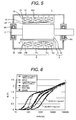
- the claw pole type motor 1 is formed of a rotor 3 that is formed on the rotating axle 2, a stator 6 that is provided coaxially via a minute space G in the circumference direction with respect to the rotor 3, a stator frame 8 which supports the stator 6, and bearings 9A and 9B that support the rotating axle 2 so as to be rotatable at both end sides of the stator frame 8.
- the rotor 3 comprises a rotor core 4 that is formed co-axially with the rotating axle 2, and permanent magnetic pole 5 that are disposed in multiples in the circumferential direction set at the outer circumference, and the stator 6 is formed of stator cores 7U, 7V and 7W and the ring coil 10 that winds onto these stator cores 7U, 7V and 7W.
- the stator cores 7U, 7V and 7W are supported by the stator frame 8 and the rotating shaft 2 is supported onto both end portions of the stator frame 8 so as to be rotatable via the bearing 9A and 9B.
- the stator cores 7U, 7V and 7W are formed from a first claw core 11A, and a second claw core 11B and the first claw core 11A, and the second claw core respectively and is formed of a claw magnetic pole 12 that has a magnetic pole surface 12F which face the rotor 3 with a minute space G and extends in the axial direction, a ring yoke portion 13 which extends at right angles from the claw magnetic pole 12 to the outer diameter side, and an outer circumference side yoke 14 which extends in the same direction as the claw magnetic pole 12 from the ring yoke portion 13.
- These magnetic poles 12 respectively form 12 poles at equal intervals in the circumferential direction.
- first and second claw cores 11A and 11B are formed in the same shape by compacting of magnetic powder by punch of a die, and a more complex magnetic pole structure can be obtained when compared to that configured by layering silicon steel plates.
- first claw core 11A and the second claw core 11B that are formed by compacting of magnetic powder are disposed such that ends extending in the axial direction 12T of the magnetic pole 12 are toward each other, and by meshing the end extending in the axial direction 12T is positioned between the matching side end extending in the axial direction 12T, a plurality of magnetic pole surfaces 12F which are concentric with the rotor 3 are formed along circumference surface of the rotor 3.
- stator cores 7U, 7V and 7W which have ring coils 10U, 10V and 10W built-in are connected in the axial direction, and by offsetting the electrical angle by 120 degrees in the circumferential direction, a 3-phase claw pole type motor is configured.
- stator 6 by molding these 3 serial stator cores 7U, 7V and 7W from an insulating resin, a stator 6 can be obtained in which the first claw core 11A and the second claw core 11B and the ring coil 10U, 10V and 10W are integral.
- the first claw core 11A and the second claw core 11B by compacting of magnetic powder, a magnetic pole structure which is complex, or in other words, one obtaining improved motor efficiency can be obtained.
- the punch for compacting of the first claw core 11A and the second claw core 11B must have punch cross-sectional area proportional to the axial direction dimensions of the compact such that buckling of the punch does not occur.
- the punch cross-sectional area must be determined based on the axial direction dimension L1 of the claw magnetic pole 12 at which the dimension in the axial direction is maximum on the first claw core 11A and the second claw core 11B.
- the end extending in the axial direction 12T of the claw magnetic pole 12 must have a flat surface which crosses the axial direction, and the surface area of that flat surface must be made proportionately large since the axial dimension L1 of the claw magnetic pole 12 is made large.
- the radial direction thickness H2 in the end extending in the axial direction 12T of the claw magnetic pole 12 is at least 2 mm or more and the surface area of the flat surface must be secured.
- a ejection taper ⁇ is necessary in the axial direction, and must be formed on the claw magnetic pole 12 to taper from the base to the end extending in the axial direction 12T in the range of 8 - 10 degrees with respect to the axial direction.
- a ejection taper 8 degrees or more is preferable when removing the compact from the die, but when it is as large as possible, the ejection operation is easier.
- the ejection taper ⁇ is made large, the surface area of the magnetic pole surface 12F of the magnetic pole 12 is reduced and magnetic properties decrease, so the ejection taper ⁇ is preferably 10 degrees or less which is small and for which there is little effect on magnetic properties.
- the magnetic powder can be subjected to compacting at high compacting pressure and thus the density of powder core can be increased to 7.5 g/cm 3 or more, and as a result motor properties higher than magnetic cores by cold-rolled steel plate (SPCC: a standard code of Japanese Industrial Standard) can be obtained.
- SPCC cold-rolled steel plate
- first claw core 11A and the second claw core 11B of this embodiment have the aforementioned configuration conditions, high density of magnetic powder is achieved and powder core having density of 7.5 g/cm 3 can be obtained and they have magnetic properties (magnetic flux density) closer to SPCC and SS400 compared to powder core having density of 7.3 g/cm 3 .
- the magnetic properties are reduced and the magnetic pole density is also low and thus in the case where a magnet whose residual magnetic flux density is high is used as the field magnet, output torque is reduced by saturation of the magnetic flux density and the like, and it can be expected that the magnetic properties will reduce.
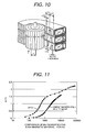
- FIG. 10 shows the structure of a claw pole type motor formed from cold-rolled steel plate (SPCC) of the prior art.
- SPCC cold-rolled steel plate
- This motor is formed by using a stator core that is formed by bending a steel plate such as SPCC and the like, and thus for small motors with a plate thickness ⁇ of up to 100 mm for which bending is possible, the limit is a thickness of about 1.6 mm.
- the stator core of this claw pole type motor is formed of a powder core of a density of 7.3 g/cm 3 which can be compacted in this configuration.
- the results of comparison of the output properties at this time, for a motor formed in the same configuration are shown in Fig. 12.
- the claw pole type motor formed of SPCC of the prior art under the current comparison condition which are residual magnetic flux density of the field magnet of 1.2T, 24 poles, rotation speed of 1000 r/min, magnetomotive force of 220 ampere-turn, have a output torque that 10 % higher compared to the motor that is formed of a powder core.
- the reason for this is, as shown in Fig. 11, when the direct current magnetizing properties of SPCC and powder core are compared, the magnetic permeability of the powder core is low, and the magnetic pole density when the same magnetic field is applied is higher for SPCC.
- the plate thickness of the powder core there is no limit of the plate thickness of the powder core to 1.6 mm or less due to the difference in the processing method. Because of this, it is possible to obtain a claw pole type motor with optimal design by increasing the degree of freedom of design by making the claw magnetic pole thick and the like.
- the stator core which has been optimally designed under the conditions of the same field magnet aforementioned and the like has a claw thickness of 2 mm, and the compacting pressure at the time of compacting can be made high and thus formation using a high density powder core becomes possible.
- the direct current magnetizing properties of the highly powder core whose density is 7.5 g/cm 3 are shown in Fig. 13.
- the magnetic permeability is improved compared to the direct current magnetizing properties of the aforementioned 7.3 g/cm 3 powder core, but do not reach the magnetic properties of SPCC.
- the results of the calculations output torque are computed for the claw pole type motor having a claw thickness of 2 mm using FEM. Manufacturing problems are disregarded and in the calculations, the difference in output torque in the case where SPCC is used in the claw pole type motor and in the case where a powder core whose density is 7.5 g/cm 3 are compared. As shown in Fig. 14, the output torque in the case where the powder core is used is 20 % higher.
- SPCC has higher magnetic permeability, but in SPCC, because eddy current generated on the inside of the metal plate is generated in the direction crossing this magnetic flux, this has the effect of contributing to reduction of the output torque. Due to this result, in a small motor of about ⁇ 100 mm, a permanent field magnet exceeding 1.2T such as a rare earth sintered magnet having a high energy product is used as the field magnet, and the claw pole type motor that is designed such that the claw thickness of the stator core is 2 mm or more can relax the effect of saturation of magnetic flux from the field magnet, and because it becomes possible to increase the density of the powder core, it is clear that it is possible to realize high motor properties. It is to be noted that the output torque of the motor is strongly influenced by the magnetic flux that passes through the claw magnetic pole, and thus a claw magnetic pole whose density is at least 7.5 g/cm 3 or more is preferable.
- Fig. 15 shows the relationship between the taper angle and the claw magnetic pole surface area. As shown in (a), when the configuration of the claw is defined and given that the claw magnetic pole surface area is 100 % when the taper angle is 0, the changes in the surface area due to the taper angle is a ⁇ b - a 2 tan ⁇ , and the relationship is that shown in (b).
- the taper angle is preferably large, but in order to suppress motor output reduction is preferably small.
- the conditions for satisfying motor properties that are greater than equal to the properties for the motor formed of SPCC require the taper angle to be up to 10° if output reduction of up to 20 % is to be permitted.
- stator using a high density (high magnetic flux density) compact core
- a high magnetomotive force using a magnet having a high residual magnetic flux density as the field magnet.
- a rare earth magnet is used as the permanent magnetic pole 5 of the rotor 3, and the magnetic flux density is made 1.2 - 1.4 tesla, and the dimensional relationship of the first claw core 11A and the second claw core 11B corresponding to this magnetic flux density was discovered by the following analysis.
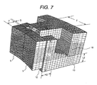
- Fig. 7 is a mesh diagram for the case of analyzing the motor properties using three-dimensional electromagnetic analysis, and the dimensions of each portion (circumferential direction average width angle T of the claw magnetic pole 12, axial direction dimension L1 of the claw magnetic pole 12, axial direction dimension L2 of the ring yoke portion 13, circumferential direction dimension H1 in the end extending in the axial direction 12T of the claw magnetic pole 12, the radial direction thickness H2 in the end extending in the axial direction 12T of the claw magnetic pole 12, the radial direction dimension F of the permanent magnetic pole 5, and the circumferential direction space G of the rotor 3 and the stator 6) are changed the parameters being studied are shown.
- the output torque can be maximized under other conditions, but in the case where the aforementioned limitations are added to the claw magnetic pole 12, as shown in Fig. 4, the ratio of the circumferential direction average width angle of the claw magnetic pole 12, T for the magnetic pitch P corresponding to 1 cycle of AC in the range 0.4 - 0.45 is the design point that obtains the most stable output torque. It is to be noted that the results were the same for the number of poles other than 24 poles and 32 poles.
- a claw pole type motor is described as the claw pole type rotating electric machine, but it is not limited to the claw pole type motor and may also be applied to a generator and the like.
Landscapes
- Engineering & Computer Science (AREA)
- Power Engineering (AREA)
- Iron Core Of Rotating Electric Machines (AREA)
- Synchronous Machinery (AREA)
Applications Claiming Priority (2)
| Application Number | Priority Date | Filing Date | Title |
|---|---|---|---|
| JP2005286634 | 2005-09-30 | ||
| JP2006239694A JP2007124884A (ja) | 2005-09-30 | 2006-09-05 | クローポール型回転電機 |
Publications (3)
| Publication Number | Publication Date |
|---|---|
| EP1770846A2 true EP1770846A2 (de) | 2007-04-04 |
| EP1770846A3 EP1770846A3 (de) | 2009-09-02 |
| EP1770846B1 EP1770846B1 (de) | 2010-11-24 |
Family
ID=37075049
Family Applications (1)
| Application Number | Title | Priority Date | Filing Date |
|---|---|---|---|
| EP06020595A Ceased EP1770846B1 (de) | 2005-09-30 | 2006-09-29 | Drehende elektrische Klauenpolmaschine |
Country Status (4)
| Country | Link |
|---|---|
| US (1) | US7605517B2 (de) |
| EP (1) | EP1770846B1 (de) |
| JP (1) | JP2007124884A (de) |
| DE (1) | DE602006018405D1 (de) |
Cited By (5)
| Publication number | Priority date | Publication date | Assignee | Title |
|---|---|---|---|---|
| WO2011076579A1 (en) * | 2009-12-21 | 2011-06-30 | Höganäs Ab (Publ) | Stator element for a modulated pole machine |
| WO2011135268A1 (fr) | 2010-04-28 | 2011-11-03 | Federal Mogul Sintertech | Phase de moteur homopolaire. |
| EP2763296A1 (de) | 2013-01-09 | 2014-08-06 | Airbus Helicopters | Elektrische Maschine mit Zwischenstücken mit mehreren Luftspalten und 3D-Magnetfluss |
| EP2814147A1 (de) | 2013-01-09 | 2014-12-17 | Airbus Helicopters | Elektrische Maschine mit mehreren Luftspalten und 3D-Magnetfluss |
| EP2656490B1 (de) * | 2010-12-21 | 2017-12-20 | Sintertech | Elektrische drehmaschine mit sogenannter doppelter homopolarer struktur |
Families Citing this family (21)
| Publication number | Priority date | Publication date | Assignee | Title |
|---|---|---|---|---|
| DE102006021247B4 (de) * | 2006-04-28 | 2012-02-02 | Bühler Motor GmbH | Elektromotor |
| JP4887128B2 (ja) * | 2006-12-07 | 2012-02-29 | 日立オートモティブシステムズ株式会社 | 回転電機 |
| US7868511B2 (en) | 2007-05-09 | 2011-01-11 | Motor Excellence, Llc | Electrical devices using disk and non-disk shaped rotors |
| WO2008141245A2 (en) | 2007-05-09 | 2008-11-20 | Motor Excellence, Llc | Electrical output generating devices and driven electrical devices having tape wound core laminate rotor or stator elements, and methods of making and use thereof |
| JP4604064B2 (ja) | 2007-06-19 | 2010-12-22 | 日立オートモティブシステムズ株式会社 | 車両用交流発電機及び回転電機 |
| TW200917626A (en) * | 2007-10-12 | 2009-04-16 | Sunonwealth Electr Mach Ind Co | Magnetic pole structure of stator with radial winding |
| JP5534636B2 (ja) * | 2007-10-26 | 2014-07-02 | キヤノン株式会社 | モータおよび駆動装置 |
| EP2061136A1 (de) * | 2007-11-19 | 2009-05-20 | Siemens Aktiengesellschaft | Elektrischer Direktantrieb für eine Walze |
| JP5171307B2 (ja) * | 2008-02-22 | 2013-03-27 | パナソニック株式会社 | クローポール型モータ及び該モータを備えたポンプ |
| JP4982439B2 (ja) * | 2008-06-30 | 2012-07-25 | 株式会社日立製作所 | 圧粉成形体 |
| US7923886B2 (en) | 2008-11-03 | 2011-04-12 | Motor Excellence, Llc | Transverse and/or commutated flux system rotor concepts |
| JP2011073028A (ja) * | 2009-09-30 | 2011-04-14 | Hitachi Ltd | 成形用パンチ金型,該成形用パンチ金型を備えた成形装置、および成形方法 |
| CN102986115A (zh) | 2010-03-15 | 2013-03-20 | 电扭矩机器股份有限公司 | 用于电动自行车的横向和/或换向通量系统 |
| WO2011115632A1 (en) | 2010-03-15 | 2011-09-22 | Motor Excellence Llc | Transverse and/or commutated flux systems configured to provide reduced flux leakage, hysteresis loss reduction, and phase matching |
| DK2548289T3 (da) * | 2010-03-15 | 2020-02-17 | Motor Excellence Llc | Tværgående og/eller kommuterede strømningssystemer med faseforskydning |
| US8482243B2 (en) * | 2010-03-25 | 2013-07-09 | Gerald K. Langreck | High acceleration rotary actuator |
| EP2641316B1 (de) | 2010-11-17 | 2019-02-13 | Motor Excellence, LLC | Quer- oder mischflusssysteme mit segmentierten statorlamellen |
| WO2012067895A2 (en) | 2010-11-17 | 2012-05-24 | Motor Excellence, Llc | Transverse and/or commutated flux system coil concepts |
| WO2012067896A2 (en) | 2010-11-17 | 2012-05-24 | Motor Excellence, Llc | Transverse and/or commutated flux systems having laminated and powdered metal portions |
| JP6227428B2 (ja) * | 2014-01-22 | 2017-11-08 | アスモ株式会社 | マルチランデル型モータ |
| FR3030931B1 (fr) * | 2014-12-18 | 2017-12-08 | Airbus Helicopters | Machine electrique a excitation separee avec au moins deux induits et un inducteur |
Citations (5)
| Publication number | Priority date | Publication date | Assignee | Title |
|---|---|---|---|---|
| DE3607452A1 (de) | 1986-03-07 | 1987-09-10 | Berger Gmbh & Co Gerhard | Stator fuer einen elektromotor |
| EP0568347A1 (de) | 1992-04-28 | 1993-11-03 | Minebea Kabushiki-Kaisha | Schrittmotor |
| US20020070627A1 (en) | 2000-09-06 | 2002-06-13 | Ward Robert W. | Stator core design |
| JP2004068041A (ja) | 2002-08-01 | 2004-03-04 | Tamagawa Seiki Co Ltd | クローポールロータの製造方法 |
| EP1569319A2 (de) | 2004-02-25 | 2005-08-31 | Robert Bosch Gmbh | Hauptelement für eine elektrische Maschine |
Family Cites Families (7)
| Publication number | Priority date | Publication date | Assignee | Title |
|---|---|---|---|---|
| DE69305118T2 (de) * | 1992-07-20 | 1997-02-06 | Gen Motors Corp | Verfahren zur Herstellung von magnetischen Rotorteilen |
| JPH09266657A (ja) * | 1996-03-27 | 1997-10-07 | Nakagawa Seimitsu Kogyo Kk | モータ |
| JP3460912B2 (ja) * | 1996-10-18 | 2003-10-27 | ミネベア株式会社 | モータ構造 |
| US5986379A (en) * | 1996-12-05 | 1999-11-16 | General Electric Company | Motor with external rotor |
| JP3458344B2 (ja) * | 1997-02-03 | 2003-10-20 | ミネベア株式会社 | モータ構造 |
| JP3944140B2 (ja) | 2003-06-04 | 2007-07-11 | 本田技研工業株式会社 | クローポール型モータのステータ |
| JP2005151785A (ja) * | 2003-11-16 | 2005-06-09 | Yoshimitsu Okawa | リング状の電機子コイルを有する同期発電機 |
-
2006
- 2006-09-05 JP JP2006239694A patent/JP2007124884A/ja active Pending
- 2006-09-27 US US11/527,410 patent/US7605517B2/en active Active
- 2006-09-29 DE DE602006018405T patent/DE602006018405D1/de active Active
- 2006-09-29 EP EP06020595A patent/EP1770846B1/de not_active Ceased
Patent Citations (5)
| Publication number | Priority date | Publication date | Assignee | Title |
|---|---|---|---|---|
| DE3607452A1 (de) | 1986-03-07 | 1987-09-10 | Berger Gmbh & Co Gerhard | Stator fuer einen elektromotor |
| EP0568347A1 (de) | 1992-04-28 | 1993-11-03 | Minebea Kabushiki-Kaisha | Schrittmotor |
| US20020070627A1 (en) | 2000-09-06 | 2002-06-13 | Ward Robert W. | Stator core design |
| JP2004068041A (ja) | 2002-08-01 | 2004-03-04 | Tamagawa Seiki Co Ltd | クローポールロータの製造方法 |
| EP1569319A2 (de) | 2004-02-25 | 2005-08-31 | Robert Bosch Gmbh | Hauptelement für eine elektrische Maschine |
Cited By (10)
| Publication number | Priority date | Publication date | Assignee | Title |
|---|---|---|---|---|
| WO2011076579A1 (en) * | 2009-12-21 | 2011-06-30 | Höganäs Ab (Publ) | Stator element for a modulated pole machine |
| WO2011135268A1 (fr) | 2010-04-28 | 2011-11-03 | Federal Mogul Sintertech | Phase de moteur homopolaire. |
| FR2961037A1 (fr) * | 2010-04-28 | 2011-12-09 | Francecol Technology | Realisation d'une phase de machine homopolaire tournante, applique a la conception de son circuit magnetique |
| EP2564490A1 (de) * | 2010-04-28 | 2013-03-06 | Federal Mogul Sintertech | Homopolare motorphase |
| US9337710B2 (en) | 2010-04-28 | 2016-05-10 | Sintertech | Homopolar motor phase |
| EP2656490B1 (de) * | 2010-12-21 | 2017-12-20 | Sintertech | Elektrische drehmaschine mit sogenannter doppelter homopolarer struktur |
| EP2763296A1 (de) | 2013-01-09 | 2014-08-06 | Airbus Helicopters | Elektrische Maschine mit Zwischenstücken mit mehreren Luftspalten und 3D-Magnetfluss |
| EP2814147A1 (de) | 2013-01-09 | 2014-12-17 | Airbus Helicopters | Elektrische Maschine mit mehreren Luftspalten und 3D-Magnetfluss |
| US9496757B2 (en) | 2013-01-09 | 2016-11-15 | Airbus Helicopters | Electric machine with intermediate pieces having multiple air gaps and a 3D magnetic flux |
| US9685828B2 (en) | 2013-01-09 | 2017-06-20 | Airbus Helicopters | Electric machine with multiple air gaps and a 3D magnetic flux |
Also Published As
| Publication number | Publication date |
|---|---|
| EP1770846B1 (de) | 2010-11-24 |
| DE602006018405D1 (de) | 2011-01-05 |
| JP2007124884A (ja) | 2007-05-17 |
| EP1770846A3 (de) | 2009-09-02 |
| US7605517B2 (en) | 2009-10-20 |
| US20070075605A1 (en) | 2007-04-05 |
Similar Documents
| Publication | Publication Date | Title |
|---|---|---|
| EP1770846A2 (de) | Drehende elektrische Klauenpolmaschine | |
| Du et al. | High torque density and low torque ripple shaped-magnet machines using sinusoidal plus third harmonic shaped magnets | |
| DK2306620T3 (en) | Rotary for permanent magnet rotary machine | |
| KR101678221B1 (ko) | Ipm형 영구자석 회전기용 회전자의 조립 방법 | |
| US8823235B2 (en) | Rotor for axial gap-type permanent magnetic rotating machine | |
| Wang et al. | Development of an axial gap motor with amorphous metal cores | |
| JP7262926B2 (ja) | ラジアルギャップ型回転電機 | |
| US20090251023A1 (en) | Permanent magnet rotating electric machine and electric power steering device using the same | |
| US20110068651A1 (en) | Rotor for permanent magnet rotating machine | |
| US8647091B2 (en) | Stator compacted in one piece | |
| US8222787B2 (en) | Electric machine | |
| JP2009111418A (ja) | 異方性磁石の製造に用いる金型、成形機、方法及び得られる磁石 | |
| CN102779639A (zh) | 多磁极各向异性永磁磁环的制备方法 | |
| CN115398777A (zh) | 铁芯片、定子铁芯、定子、旋转电机及铁芯片的制造方法 | |
| KR20120062800A (ko) | 영구자석식 회전기용 회전자 | |
| CN101795024A (zh) | 一种具有非晶态合金铁心的横向磁场电机 | |
| Yoshida et al. | Reduction of iron loss in ultrahigh-speed interior winding synchronous motor using magnetic composite material | |
| WO2013147157A1 (ja) | 回転電機 | |
| CN100578893C (zh) | 爪极式旋转电机 | |
| Jack | Experience with using soft magnetic composites for electrical machines | |
| US9608483B2 (en) | Electrical machine with magnetic flux intensifier | |
| CN206948063U (zh) | 低转矩波动内置式永磁电机转子 | |
| CN203660689U (zh) | 电机转子 | |
| CN201134701Y (zh) | 一种盘式电机 | |
| CN105680591B (zh) | 轮辐式永磁自启动电机转子及其加工方法 |
Legal Events
| Date | Code | Title | Description |
|---|---|---|---|
| PUAI | Public reference made under article 153(3) epc to a published international application that has entered the european phase |
Free format text: ORIGINAL CODE: 0009012 |
|
| AK | Designated contracting states |
Kind code of ref document: A2 Designated state(s): AT BE BG CH CY CZ DE DK EE ES FI FR GB GR HU IE IS IT LI LT LU LV MC NL PL PT RO SE SI SK TR |
|
| AX | Request for extension of the european patent |
Extension state: AL BA HR MK YU |
|
| PUAL | Search report despatched |
Free format text: ORIGINAL CODE: 0009013 |
|
| AK | Designated contracting states |
Kind code of ref document: A3 Designated state(s): AT BE BG CH CY CZ DE DK EE ES FI FR GB GR HU IE IS IT LI LT LU LV MC NL PL PT RO SE SI SK TR |
|
| AX | Request for extension of the european patent |
Extension state: AL BA HR MK RS |
|
| 17P | Request for examination filed |
Effective date: 20090911 |
|
| 17Q | First examination report despatched |
Effective date: 20091120 |
|
| AKX | Designation fees paid |
Designated state(s): DE FR IT |
|
| GRAP | Despatch of communication of intention to grant a patent |
Free format text: ORIGINAL CODE: EPIDOSNIGR1 |
|
| GRAS | Grant fee paid |
Free format text: ORIGINAL CODE: EPIDOSNIGR3 |
|
| RIN1 | Information on inventor provided before grant (corrected) |
Inventor name: MASAKI, RYOZOHITACHI IND. EQUIP. SYST. CO.,LTD. Inventor name: ISHIHARA, CHIO Inventor name: ENOMOTO, YUJIHITACHI, LTD. Inventor name: ITO, MOTOYAHITACHI, LTD. Inventor name: OHIWA,SHOJI |
|
| GRAA | (expected) grant |
Free format text: ORIGINAL CODE: 0009210 |
|
| AK | Designated contracting states |
Kind code of ref document: B1 Designated state(s): DE FR IT |
|
| REF | Corresponds to: |
Ref document number: 602006018405 Country of ref document: DE Date of ref document: 20110105 Kind code of ref document: P |
|
| REG | Reference to a national code |
Ref country code: FR Ref legal event code: TP |
|
| PLBE | No opposition filed within time limit |
Free format text: ORIGINAL CODE: 0009261 |
|
| STAA | Information on the status of an ep patent application or granted ep patent |
Free format text: STATUS: NO OPPOSITION FILED WITHIN TIME LIMIT |
|
| 26N | No opposition filed |
Effective date: 20110825 |
|
| REG | Reference to a national code |
Ref country code: DE Ref legal event code: R097 Ref document number: 602006018405 Country of ref document: DE Effective date: 20110825 |
|
| REG | Reference to a national code |
Ref country code: FR Ref legal event code: PLFP Year of fee payment: 11 |
|
| REG | Reference to a national code |
Ref country code: FR Ref legal event code: PLFP Year of fee payment: 12 |
|
| REG | Reference to a national code |
Ref country code: FR Ref legal event code: PLFP Year of fee payment: 13 |
|
| PGFP | Annual fee paid to national office [announced via postgrant information from national office to epo] |
Ref country code: DE Payment date: 20190917 Year of fee payment: 14 |
|
| PGFP | Annual fee paid to national office [announced via postgrant information from national office to epo] |
Ref country code: FR Payment date: 20200812 Year of fee payment: 15 |
|
| PGFP | Annual fee paid to national office [announced via postgrant information from national office to epo] |
Ref country code: IT Payment date: 20200812 Year of fee payment: 15 |
|
| REG | Reference to a national code |
Ref country code: DE Ref legal event code: R119 Ref document number: 602006018405 Country of ref document: DE |
|
| PG25 | Lapsed in a contracting state [announced via postgrant information from national office to epo] |
Ref country code: DE Free format text: LAPSE BECAUSE OF NON-PAYMENT OF DUE FEES Effective date: 20210401 |
|
| PG25 | Lapsed in a contracting state [announced via postgrant information from national office to epo] |
Ref country code: FR Free format text: LAPSE BECAUSE OF NON-PAYMENT OF DUE FEES Effective date: 20210930 |
|
| PG25 | Lapsed in a contracting state [announced via postgrant information from national office to epo] |
Ref country code: IT Free format text: LAPSE BECAUSE OF NON-PAYMENT OF DUE FEES Effective date: 20210929 |