EP1770847A2 - Moteur rotatif à aimants permants - Google Patents
Moteur rotatif à aimants permants Download PDFInfo
- Publication number
- EP1770847A2 EP1770847A2 EP06254872A EP06254872A EP1770847A2 EP 1770847 A2 EP1770847 A2 EP 1770847A2 EP 06254872 A EP06254872 A EP 06254872A EP 06254872 A EP06254872 A EP 06254872A EP 1770847 A2 EP1770847 A2 EP 1770847A2
- Authority
- EP
- European Patent Office
- Prior art keywords
- magnetic pole
- angle
- type connecting
- connecting portion
- constituent
- Prior art date
- Legal status (The legal status is an assumption and is not a legal conclusion. Google has not performed a legal analysis and makes no representation as to the accuracy of the status listed.)
- Withdrawn
Links
- 239000000470 constituent Substances 0.000 claims description 168
- 238000004804 winding Methods 0.000 claims description 16
- 230000000149 penetrating effect Effects 0.000 claims description 5
- 230000000052 comparative effect Effects 0.000 description 7
- 238000004519 manufacturing process Methods 0.000 description 4
- 238000010586 diagram Methods 0.000 description 2
- 230000004907 flux Effects 0.000 description 2
- 230000003247 decreasing effect Effects 0.000 description 1
Images




Classifications
-
- H—ELECTRICITY
- H02—GENERATION; CONVERSION OR DISTRIBUTION OF ELECTRIC POWER
- H02K—DYNAMO-ELECTRIC MACHINES
- H02K1/00—Details of the magnetic circuit
- H02K1/06—Details of the magnetic circuit characterised by the shape, form or construction
- H02K1/12—Stationary parts of the magnetic circuit
- H02K1/14—Stator cores with salient poles
-
- H—ELECTRICITY
- H02—GENERATION; CONVERSION OR DISTRIBUTION OF ELECTRIC POWER
- H02K—DYNAMO-ELECTRIC MACHINES
- H02K1/00—Details of the magnetic circuit
- H02K1/06—Details of the magnetic circuit characterised by the shape, form or construction
- H02K1/12—Stationary parts of the magnetic circuit
- H02K1/14—Stator cores with salient poles
- H02K1/146—Stator cores with salient poles consisting of a generally annular yoke with salient poles
- H02K1/148—Sectional cores
-
- H—ELECTRICITY
- H02—GENERATION; CONVERSION OR DISTRIBUTION OF ELECTRIC POWER
- H02K—DYNAMO-ELECTRIC MACHINES
- H02K1/00—Details of the magnetic circuit
- H02K1/06—Details of the magnetic circuit characterised by the shape, form or construction
- H02K1/12—Stationary parts of the magnetic circuit
-
- H—ELECTRICITY
- H02—GENERATION; CONVERSION OR DISTRIBUTION OF ELECTRIC POWER
- H02K—DYNAMO-ELECTRIC MACHINES
- H02K1/00—Details of the magnetic circuit
- H02K1/06—Details of the magnetic circuit characterised by the shape, form or construction
- H02K1/12—Stationary parts of the magnetic circuit
- H02K1/18—Means for mounting or fastening magnetic stationary parts on to, or to, the stator structures
-
- H—ELECTRICITY
- H02—GENERATION; CONVERSION OR DISTRIBUTION OF ELECTRIC POWER
- H02K—DYNAMO-ELECTRIC MACHINES
- H02K29/00—Motors or generators having non-mechanical commutating devices, e.g. discharge tubes or semiconductor devices
- H02K29/03—Motors or generators having non-mechanical commutating devices, e.g. discharge tubes or semiconductor devices with a magnetic circuit specially adapted for avoiding torque ripples or self-starting problems
-
- H—ELECTRICITY
- H02—GENERATION; CONVERSION OR DISTRIBUTION OF ELECTRIC POWER
- H02K—DYNAMO-ELECTRIC MACHINES
- H02K21/00—Synchronous motors having permanent magnets; Synchronous generators having permanent magnets
- H02K21/02—Details
- H02K21/021—Means for mechanical adjustment of the excitation flux
- H02K21/022—Means for mechanical adjustment of the excitation flux by modifying the relative position between field and armature, e.g. between rotor and stator
Definitions
- the present invention relates to a permanent magnet rotary motor.
- stator core there is known such a stator core that has an annular yoke and magnetic pole constituent member disposed inside the yoke.
- the magnetic pole constituent member comprises a plurality of pole columns, magnetic pole surface constituent sections formed on the pole column and connecting portions connecting two adjacent sections among the magnetic pole surface constituent sections.
- Japanese Patent Publication Application No. 2002-199630 discloses a permanent magnet rotary motor in which pole columns are disposed at unequal intervals to vary the dimensions between adjacent pole columns to reduce the cogging torque.
- Japanese Patent Publication Application No. 2002-10539 discloses a permanent magnet rotary motor in which a plurality of holes are formed discontinuously along an axial direction in its connecting portions and are opened both inwardly in a radial direction and toward a slot between two adjacent pole columns. The plurality of holes are formed in order to prevent leakage of magnetic flux among the magnetic poles.
- An object of the present invention is to provide a permanent magnet rotary motor in which the cogging torque can be reduced without largely reducing the torque.
- Another object of the present invention is to provide a permanent magnet rotary motor in which the inductance can be balanced in its exciting winding sections.
- Still another object of the present invention is to provide a permanent magnet rotary motor, which can be easily manufactured and in which the cogging torque can be reduced,
- a permanent magnet rotary motor of the present invention comprises a rotor, a stator core and N (N is an even number of 4 or more) exciting winding sections.
- the rotor includes a rotor core fixed to a rotary shaft and a plurality of permanent-magnet magnetic pole sections composed of permanent magnets attached to the rotor core.
- the stator core includes an annular yoke, N pole columns disposed inside the annular yoke at intervals in a circumferential direction of the yoke with one end of the pole column being connected to the yoke and the other end thereof being positioned on an inner side than the one end in a radial direction of the yoke.
- the stator core also includes N magnetic pole surface constituent sections respectively formed on the other end of the N pole columns, each having on its inner side a magnetic pole surface facing the rotor, and N connecting portions connecting two adjacent sections among the magnetic pole surface constituent sections.
- Each of the N connecting portions is formed with one or more through-holes penetrating the connecting portion in the radial direction.
- the N exciting winding sections are mounted onto the N pole columns of the stator core respectively.
- the N connecting portions include N/2 first type connecting portions and N/2 second type connecting portions, and the first and second type connecting portions are alternately disposed in a circumferential direction of the rotor.
- first type connecting portion When an angle formed between two virtual lines respectively connecting a center of the rotary shaft and both ends , mutually opposed in the circumferential direction, of the first type connecting portion is defined as a first angle ⁇ 1 and an angle formed between two virtual lines respectively connecting the center of the rotary shaft and both ends, mutually opposed in the circumferential direction, of the second type connecting portion is defined as a second angle ⁇ 2, a relationship between the first angle ⁇ 1 and the second angle ⁇ 2 is ⁇ 1> ⁇ 2.
- the first type connecting portion is formed with a through-hole, which extends from a center position of the first type connecting portion as viewed in an axial direction of the rotary shaft toward both sides in the axial direction.
- the second type connecting portion is formed with a through-hole, which extends from a center position of the second type connecting portion as viewed in the axial direction toward both sides in the axial direction.
- the length of the through-hole formed in the first type connecting portion is longer than the length of the through-hole formed in the second type connecting portion in the circumferential direction.
- the length of the through-hole formed in the first type connecting portion is shorter than the length of the through-hole formed in the second type connecting portion in the axial direction.
- an inner circumferential portion of the stator core may be constituted by three parts disposed along the axial direction of the rotary shaft: (1) a part where no through-holes are formed in all of the connecting portions disposed in the circumferential direction; (2) a part where through-holes are alternately formed in the connecting portions disposed in the circumferential direction; and (3) a part where through-holes are formed in all of the connection portions disposed in the circumferential direction.
- the through-holes are formed only in the second-type connecting portions, the length of which in the circumferential direction is shorter than that of the first type connection portions.
- the first angle ⁇ 1 of the first type connecting portion is appropriately larger than the second angle ⁇ 2 of the second type connecting portion so that the formulae (A) to (C) are satisfied.
- the leakage magnetic flux is reduced to prevent the torque from decreasing.
- the cogging torque can be reduced without largely reducing the torque.
- the inductance in the exciting winding sections can be balanced by alternately disposing in the circumferential direction longer through-holes and shorter through-holes, the shorter through-hole having a length shorter than the longer through-hole in the axial direction.
- the first type connecting portion may be formed with a first through-hole, which extends from one end of the first type connecting portion in the axial direction of the rotary shaft toward the other end thereof, and a second through-hole, which extends from the other end of the first type connecting portion in the axial direction toward the one end.
- the second type connecting portion may be formed with a third through-hole, which extends from one end of the second type connecting portion in the axial direction toward the other end thereof, and a fourth through-hole, which extends from the other end of the second type connecting portion in the axial direction toward the one end.
- the length, in the circumferential direction, of the first and second through-holes formed in the first type connecting portion is longer than the length, in the circumferential direction, of the third and fourth through-holes formed in the second type connecting portion.
- the length, in the axial direction, of the first and second through-holes formed in the first type connecting portion is shorter than the length, in the axial direction, of the third and fourth through-holes formed in the second type connecting portion.
- the first through-hole and the second through-hole may be equal to each other in the axial direction, and the third through-hole and the fourth through-hole may be equal to each other in the axial direction.
- the first type connecting portion can be formed with a through-hole, which extends from one end of the first type connecting portion in the axial direction of the rotary shaft toward the other end thereof; and the second type connecting portion can be formed with a through-hole, which extends from one end of the second type connecting portion in the axial direction toward the other end thereof.
- the length, in the circumferential direction, of the through-hole formed in the first type connecting portion is longer than the length, in the circumferential direction, of the through-hole formed in the second type connecting portion.
- the length, in the axial direction, of the through-hole formed in the first type connecting portion is shorter than the length, in the axial direction, of the through-hole formed in the second type connecting portion. In this manner also, the cogging torque can be reduced without largely reducing the torque. Also, the inductance in the exciting winding sections can be balanced.
- a value ( ⁇ 2/ ⁇ 1) obtained by dividing the second angle ⁇ 2 by the first angle ⁇ 1 is preferably set to a range of 0.25 ⁇ 2/ ⁇ 1 ⁇ 0.35. With this arrangement, the inductance in the exciting winding sections can be more reliably balanced.
- the angle range, measured in the circumferential direction, of the through-hole formed in the first type connecting portion may be equal to the first angle ⁇ 1; and the angle range, measured in the circumferential direction, of the through-hole formed in the second type connecting portion may be equal to the second angle ⁇ 2.
- the stator core of the permanent magnet rotary motor according to the present invention includes a yoke and a magnetic pole constituent member disposed inside the yoke.
- the magnetic pole constituent member may be composed of first-kind, second-kind, and third-kind magnetic pole constituent steel-plate layers which are overlaid on one another.
- Each of the layers is made of a magnetic steel-plate, and includes a pole column constituent portion partially constituting the pole column and a magnetic pole surface constituent portion partially constituting the magnetic pole surface constituent section.
- Two different intermediate portions are formed between two adjacent portions among the magnetic pole surface constituent portions included in each of the first-kind to third-kind magnetic pole constituent steel-plate layers; i.e., first intermediate portions and second intermediate portions each have a different angle range measured in the circumferential direction.
- an angle formed between two virtual lines respectively connecting a center of the rotor and two ends, mutually opposed in the circumferential direction, of the two adjacent magnetic pole surface constituent portions is a first angle ⁇ 1.
- an angle formed between two virtual lines respectively connecting the center of the rotor and two ends, mutually opposed in the circumferential direction, of the two adjacent magnetic pole surface constituent portions is a second angle ⁇ 2, which is smaller than the first angle 61.
- Both of the first and second intermediate portions of the first-kind magnetic pole constituent steel-plate layer are opened to partially form the through-holes.
- the first intermediate portions of the second-kind magnetic pole constituent steel-plate layer partially constitute the connecting portions, and the second intermediate portions thereof are opened to partially form the through-holes.
- Both of the first intermediate portions and the second intermediate portions of the third-kind magnetic pole constituent steel-plate layer partially form the connecting portions.
- the magnetic pole constituent member is composed of the third-kind magnetic pole constituent steel-plate layer, the second-kind magnetic pole constituent steel-plate layer, the first-kind magnetic pole constituent steel-plate layer, the second-kind magnetic pole constituent steel-plate layer and the third-kind magnetic pole constituent steel-plate layer which are overlaid on one another in this order so that the ratio for the number of layers is 1:2:4:2:1.
- the through-hole which extends from a center position of the first type connecting portion, and the through-hole, which extends from a center position of the second type connecting portion, are formed.
- stator core in which the length of the through-hole formed in the first type connecting portion is shorter than the length of the through-hole formed in the second type connecting portion, by simply overlaying in the axial direction of the rotor three kinds of magnetic pole constituent steel-plate layers each made of a magnetic steel-plate.
- the magnetic pole constituent member may be composed of the first-kind magnetic pole constituent steel-plate layer, the second-kind magnetic pole constituent steel-plate layer, the third-kind magnetic pole constituent steel-plate layer, the second-kind magnetic pole constituent steel-plate layer and the first-kind magnetic pole constituent steel-plate layer which are overlaid on one another in this order so that the ratio for the number of layers is 2:2:2:2:2.
- the first and second through-holes are formed in both ends of the first type connecting portion
- the third and fourth through-holes are formed in both ends of the second type connecting portion.
- stator core in which the length of the first and second through-holes is shorter than the length of the third and fourth through-holes, by simply overlaying in the axial direction of the rotor three kinds of magnetic pole constituent steel-plate layers each made of a magnetic steel-plate.
- the magnetic pole constituent member may be composed of the third-kind magnetic pole constituent steel-plate layer, the second-kind magnetic pole constituent steel-plate layer and the first-kind magnetic pole constituent steel-plate layer which are overlaid on one another in this order so that the ratio for the number of layers is 2:4:4.
- the inner circumferential portion of the stator core may be constituted by three parts disposed along the axial direction of the rotary shaft: (1) a part where no through-holes are formed in all of the connecting portions disposed in the circumferential direction; (2) a part where through-holes are alternately formed in the connecting portions disposed in the circumferential direction; and (3) a part where through-holes are formed in all of the connection portions disposed in the circumferential direction.
- the cogging torque can be reduced without largely reducing the torque.
- the inductance in the exciting winding sections can be balanced by alternately disposing in the circumferential direction longer through-holes and shorter through-holes, the shorter through-hole having a length shorter than the longer through-hole in the axial direction.
- Fig. 1 is a schematic diagram of a permanent magnet rotary motor according to a first embodiment of the present invention.
- the permanent magnet rotary motor of the first embodiment comprises a rotor 1 and a stator 3 as shown in Fig. 1.
- the rotor 1 includes a rotor core 5 fixed to a rotary shaft 2 and eight permanent-magnet magnetic pole sections composed of plate-like permanent magnets 7, which are disposed on an outer surface of the rotor core 5 at equal intervals in a circumferential direction of the rotor core 5.
- one permanent magnet 7 constitutes one permanent-magnet magnetic pole section.
- the rotor core 5 is composed of a plurality of electromagnetic steel-plates which are overlaid on one another.
- the eight permanent magnets 7 are arranged on the surface of the rotor core 5 so that N-pole and S-pole appear alternately along the circumferential direction.
- the stator 3 includes a stator core 9 and exciting winding sections 11.
- the exciting winding sections 11 are indicated with a broken line in Fig. 1.
- the stator core 9 includes an annular yoke 13 and a magnetic pole constituent member 15 arranged inside the annular yoke 13 as shown in Figs. 1 to 3.
- Fig. 2 is a perspective view of the stator core 9
- Fig. 3 is a partial illustration of the stator core 9 as viewed from the inside thereof (rotor side).
- the pole columns 17 are arranged inside the yoke 13 at intervals in the circumferential direction, and each of the pole columns 17 has one end, which is connected to the yoke 13, and the other end, which is positioned at an inner side than the one end in a radial direction of the yoke. In this embodiment; each of the pole columns 17 has a projection 17a on the one end.
- the projection 17a is fitted into a recess 13a formed in the inner periphery of the yoke 13, thereby connecting the pole column 17 to the yoke 13.
- Each of the magnetic pole surface constituent sections 19 has on its inner side a magnetic pole surface 19a, which is formed on the other end of the pole column 17 and faces the rotor 1.
- the N (6) connecting portions 21A, 21B respectively connect two adjacent sections among the magnetic pole surface constituent sections 19, and include N/2 (3) first type connecting portions 21A and N/2 (3) second type connecting portions 21B.
- the first type connection portions 21A and the second type connecting portions 21B are alternately disposed in a circumferential direction of the rotor.
- first type connecting portion 21A When an angle formed between two virtual lines respectively connecting a center C of the rotary shaft 2 of the rotor 1 and both ends, mutually opposed in the circumferential direction, of the first type connecting portion 21A is defined as a first angle ⁇ 1 and an angle formed between two virtual lines respectively connecting the center C of the rotary shaft 2 of the rotor 1 and both ends, mutually opposed in the circumferential direction, of the second type connecting portion 21B is defined as a second angle ⁇ 2, a relationship between the first angle ⁇ 1 and the second angle ⁇ 2 is ⁇ 1> ⁇ 2.
- a value obtained by dividing the second angle ⁇ 2 by the first angle ⁇ 1 ( ⁇ 2/ ⁇ 1) is within a range of 0.25 ⁇ 2/ ⁇ 1 ⁇ 0.35.
- the first type connecting portion 21A is formed with a through-hole H1, which extends from a center position of the first type connecting portion 21A as viewed in an axial direction of the rotary shaft 2 toward both sides in the axial direction (the axial direction of the rotary shaft 2 indicated with an arrow AD) as shown in Fig. 3 in detail.
- the second type connecting portion 21B is formed with a through-hole H2, which extends from a center position of the second type connecting portion 21B as viewed in the axial direction toward both sides in the axial direction (indicated with arrow AD).
- an angle range measured in the circumferential direction (in a circumferential direction of the rotary shaft 2 indicated with an arrow PD) of the through-hole H1 formed in the first type connecting portion 21A is equal to the first angle 61.
- An angle range measured in the circumferential direction of the through-hole H2 formed in the second type connecting portion 21B is equal to the second angle ⁇ 2. Therefore, the length, in the circumferential direction, of the through-hole H1 formed in the first type connecting portion 21A is longer than the length, in the circumferential direction, of the through-hole H2 formed in the second type connecting portion 21B.
- the length L1, in the axial direction, of the through-hole H1 formed in the first type connecting portion 21A is shorter than the length L2, in the axial direction, of the through-hole H2 formed in the second type connecting portion 21B.
- the ratio of the length L1 of the through-hole H1 with respect to the length L2 of the through-hole H2 is 1:2.
- the magnetic pole constituent member 15 is composed of a plurality of magnetic steel-plates, which are overlaid on one another.
- the magnetic pole constituent member 15 is composed of a combination of a first-kind magnetic pole constituent steel-plate layer 27 shown in Fig. 4, a second-kind magnetic pole constituent steel-plate layer 29 shown in Fig. 5 and a third-kind magnetic pole constituent steel-plate layer 31 shown in Fig. 6, which are overlaid on one another.
- the first-kind magnetic pole constituent steel-plate layer 27 is composed of six divided magnetic steel-plates 27A to 27F as shown in Fig. 4.
- Each of the magnetic steel-plates includes a pole column constituent portion 27a that constitutes the pole column 21 and a magnetic pole surface constituent portion 27b that constitutes the magnetic pole surface constituent section 19.
- Two kinds of intermediate portions are formed between two ends, adjacent to each other in the circumferential direction, of the magnetic pole surface constituent portions 27b. That is, the intermediate portions are a first intermediate portion 27c in which the first angle ⁇ 1 is formed between two virtual lines respectively connecting two ends of the first intermediate portion 27c and the center C of the rotor, and a second intermediate portions 27d in which the second angle ⁇ 2, smaller than the first angle ⁇ 1, is formed between two virtual lines respectively connecting the two ends of the second intermediate portion 27d and the center C of the rotor.
- the first intermediate portions 27c and the second intermediate portions 27d are disposed alternately in the circumferential direction. Both of the first intermediate portions 27c and the second intermediate portions 27d are opened to partially form the through-holes H1 and H2.
- the second-kind magnetic pole constituent steel-plate layer 29 is composed of three divided magnetic steel-plates 29A to 29C.
- Each of the magnetic steel-plates includes two pole column constituent portions 29a that constitute the pole column 21 and two magnetic pole surface constituent portions 29b that constitute the magnetic pole surface constituent section 19.
- Two kinds of intermediate portions are formed between two ends, adjacent to each other in the circumferential direction, of the magnetic pole surface constituent portions 29b.
- the intermediate portions are a first intermediate portion 29c in which the first angle ⁇ 1 is formed between two virtual lines respectively connecting two ends of the first intermediate portions 29c and the center C of the rotor, and a second intermediate portions 29d in which the second angle ⁇ 2, smaller than the first angle ⁇ 1, is formed between two virtual lines respectively connecting the two ends of the second intermediate portions 29d and the center C of the rotor.
- the first intermediate portion 29c and the second intermediate portion 29d are alternately disposed in the circumferential direction.
- the first intermediate portion 29c is formed of a connecting-portion constituent portion 29e that partially constitutes the first type connecting portion 21A.
- the second intermediate portion 29d is opened to partially form the through-hole H2.
- the third-kind magnetic pole constituent steel-plate layer 31 is composed of a magnetic steel-plate and includes six pole column constituent portions 31a that constitute the pole columns 21, and six magnetic pole surface constituent portions 31b that constitute the magnetic pole surface constituent sections 19.
- Two kinds of intermediate portions are formed between two ends, adjacent to each other in the circumferential direction, the magnetic pole surface constituent portions 31b. That is, the intermediate portions are a first intermediate portion 31c in which the first angle ⁇ 1 is formed between two virtual lines respectively connecting two ends of the intermediate portions 31c and the center C of the rotor, and a second intermediate portions 31d in which the second angle ⁇ 2, smaller than the first angle ⁇ 1, is formed between two virtual lines respectively connecting the two ends of the intermediate portion 31d and the center C of the rotor.
- the first intermediate portion 31c and the second intermediate portion 31d are alternately disposed in the circumferential direction.
- the first intermediate portion 31c is formed of a connecting-portion constituent portion 31e that partially constitutes the first type connecting portion 21A
- the second intermediate portion 31d is formed of a connecting-portion constituent portion 31f that partially constitutes the second type connecting portion 21B.
- the magnetic pole constituent member 15 is composed of the third-kind magnetic pole constituent steel-plate layer 31, the second-kind magnetic pole constituent steel-plate layers 29, the first-kind magnetic pole constituent steel-plate layers 27, the second-kind magnetic pole constituent steel-plate layers 29 and the third-kind magnetic pole constituent steel-plate layer 31, which are overlaid on one another in this order so that the ratio for the number of plates is 1:2:4:2:1.
- the inner circumferential portion of the stator core (constituted by the magnetic pole surface constituent section 19, and the first and second type connecting portions 21A, 21B) are constituted by three parts disposed along the axial direction of the rotary shaft: (1) a part constituted by the third-kind magnetic pole constituent steel-plate layer 31 where no through-holes are formed in all of the connecting portions disposed in the circumferential direction; (2) a part constituted by the second-kind magnetic pole constituent steel-plate layer 29 where through-holes are alternately formed in the connecting portions disposed in the circumferential direction; and (3) a part constituted by the first-kind magnetic pole constituent steel-plate layer 27 where through-holes are formed in all of the connection portions disposed in the circumferential direction.
- FIG. 7 is a perspective view of a stator core 109 used in a permanent magnet rotary motor in accordance with a second embodiment of the present invention.
- Fig. 8 is a partial illustration of the stator core 109 used in the permanent magnet rotary motor shown in Fig. 7 as viewed from an inner side (rotor side) thereof.
- the permanent magnet rotary motor in accordance with the second embodiment has the same structure as that of the permanent magnet rotary motor in accordance with the first embodiment except for the structure of the connecting portion of the stator core.
- a first type connecting portion 121A is formed with a first through-hole H11, which extends from one end toward the other end of the first type connecting portion 121A in an axial direction (arrow AD) of the rotary shaft 2. and a second through-hole H12, which extends from the other end toward the one end of the first type connecting portion 121A in the axial direction.
- the second type connecting portion 121B is formed with a third through-hole H13, which extends from one end toward the other end of the second type connecting portion 121B in the axial direction, and a fourth through-hole H14, which extends from the other end toward the one end of the second type connecting portion 121B in the axial direction.
- a length L11, in the axial direction, of the first through-hole H11 is equal to a length L12, in the axial direction, of the second through-hole H12.
- a length L13, in the axial direction, of the third through-hole H13 is equal to a length L14, in the axial direction, of the fourth through-hole H14.
- the lengths L11, L12, in the axial direction, of the first and second through-holes H11 and H12 formed in the first type connecting portion 121A is respectively shorter than the length L13, L14, in the axial direction, of the third and fourth through-holes H13 and H14 formed in the second type connecting portion.
- the ratio between the lengths L11, L12 of the through-holes H11 and H12 and the lengths L13, L14 of the through-holes H13 and H14 is 1:2.
- the magnetic pole constituent member 115 is composed of the first-kind magnetic pole constituent steel-plate layers 27 shown in Fig. 4, the second-kind magnetic pole constituent steel-plate layers 29 shown in Fig. 5, the third-kind magnetic pole constituent steel-plate layers 31 shown in Fig. 6, the second-kind magnetic pole constituent steel-plate layers 29 and the first-kind magnetic pole constituent steel-plate layers 27, which are overlaid in this order so that the ratio for the number of plates is 2:2:2:2:2.
- Fig. 9 is a perspective view of a stator core 209 used in a permanent magnet rotary motor in accordance with a third embodiment of the present invention.
- Fig. 10 is a partial illustration of the stator core 209 used in the permanent magnet rotary motor shown in Fig. 9 as viewed from an inner side (rotor side) thereof.
- the permanent magnet rotary motor in accordance with the third embodiment has the same structure as that of the permanent magnet rotary motor in accordance with the first embodiment except for the structure of the connecting portion of the stator core.
- the first type connecting portion 221A is formed with a through-hole H21, which extends from one end toward the other end of the first type connecting portion 221A in the axial direction of the rotary shaft 2 (arrow AD).
- the second type connecting portion 221B is formed with a through-hole H22, which extends from one end toward the other end of the second type connecting portion 221B in the axial direction.
- the length L21, in the axial direction, of the through-hole H21, formed in the first type connecting portion 221A is shorter than the length L22, in the axial direction, of the through-hole H22 formed in the second type connecting portion 221B.
- the ratio between the length L21 of the through-hole H21 and the length L22 of the through-hole H22 is 1:2.
- the magnetic pole constituent member 215 is constructed of the third-kind magnetic pole constituent steel-plate layers 31 shown in Fig. 6, the second-kind magnetic pole constituent steel-plate layers 29 shown in Fig. 5 and the first-kind magnetic pole constituent steel-plate layers 27 shown in Fig. 4 which are overlaid in this order so that the ratio for the number of plates is 2:4:4.
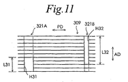
- Fig. 11 is a partial illustration of a stator core 309 used in a permanent magnet rotary motor in accordance with a varied or modified embodiment of the present invention, as viewed from an inner side (rotor side) thereof.
- the permanent magnet rotary motor in accordance with the third embodiment has the same structure as that of the permanent magnet rotary motor in accordance with the first embodiment except for the structure of the connecting portion of the stator core.
- the first type connecting portion 321A is formed with a through-hole H31, which extends from one end toward the other end of the first type connecting portion 321A in the axial direction of the rotary shaft 2(arrow AD).
- the second type connecting portion 321B is formed with a through-hole H32, which extends from one end toward the other end of the second type connecting portion 321B in the axial direction.
- the length L31, in the axial direction, of the through-hole H31 formed in the first type connecting portion 321A is shorter than the length L32, in the axial direction, of the through-hole H32 formed in the second type connecting portion 321B.
- the ratio between the length L31 of the through-hole H31 and the length L32 of the through-hole H32 is 1:2.
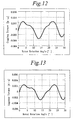
- Figs. 12 to 14 respectively show the relationships between the rotation angle and the cogging torque of the rotor in the respective permanent magnet rotary motors according to the first to third embodiments.
- Fig. 15 shows a relationship between the rotation angle and the cogging torque of the rotor of a permanent magnet rotary motor of a varied or modified embodiment of the present invention shown in Fig. 11.
- Fig. 12 to 14 respectively show the relationships between the rotation angle and the cogging torque of the rotor in the respective permanent magnet rotary motors according to the first to third embodiments.
- Fig. 15 shows a relationship between the rotation angle and the cogging torque of the rotor of a permanent magnet rotary motor of a varied or modified embodiment of the present invention shown in Fig. 11.
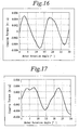
- FIG. 16 shows a relationship between the rotation angle and the cogging torque of the rotor of a permanent magnet rotary motor of a comparative example 1, in which the magnetic pole constituent member is formed by overlaying only the first-kind magnetic pole constituent steel-plate layers 27 shown in Fig. 4 (in this case, the connecting portions are all opened).
- Fig. 17 shows a relationship between the rotation angle and the cogging torque of the rotor of a permanent magnet rotary motor of a comparative example 2, in which the magnetic pole constituent member is formed by overlaying only the second-kind magnetic pole constituent steel-plate layers 29 shown in Fig. 5 (in this case, the connecting portions are alternately opened).
- Fig. 17 shows a relationship between the rotation angle and the cogging torque of the rotor of a permanent magnet rotary motor of a comparative example 1, in which the magnetic pole constituent member is formed by overlaying only the first-kind magnetic pole constituent steel-plate layers 27 shown in Fig. 4 (in this case, the connecting portions are all opened).
- Fig. 17 shows
- FIG. 18 shows a relationship between the rotation angle and the cogging torque of the rotor of a permanent magnet rotary motor of a comparative example 3, in which the magnetic pole constituent member was formed by overlaying only the second-kind magnetic pole constituent steel-plate layers 29 shown in Fig. 6 (in this case, the connecting portions are all closed).
- Figs. 12 to 18 demonstrate that, the cogging torque can be reduced in the permanent magnet rotary motors according to the first to third embodiments, compared to the permanent magnet rotary motors of the comparative examples 1 to 3, in which the magnetic pole constituent member is composed by overlaying only one of the first-kind, second-kind, and third-kind magnetic pole constituent steel-plate layers.
Landscapes
- Engineering & Computer Science (AREA)
- Power Engineering (AREA)
- Iron Core Of Rotating Electric Machines (AREA)
- Permanent Magnet Type Synchronous Machine (AREA)
- Permanent Field Magnets Of Synchronous Machinery (AREA)
- Dc Machiner (AREA)
Applications Claiming Priority (1)
| Application Number | Priority Date | Filing Date | Title |
|---|---|---|---|
| JP2005272564A JP4476202B2 (ja) | 2005-09-20 | 2005-09-20 | 永久磁石型回転モータ |
Publications (2)
| Publication Number | Publication Date |
|---|---|
| EP1770847A2 true EP1770847A2 (fr) | 2007-04-04 |
| EP1770847A3 EP1770847A3 (fr) | 2013-10-23 |
Family
ID=37715984
Family Applications (1)
| Application Number | Title | Priority Date | Filing Date |
|---|---|---|---|
| EP06254872.2A Withdrawn EP1770847A3 (fr) | 2005-09-20 | 2006-09-20 | Moteur rotatif à aimants permants |
Country Status (5)
| Country | Link |
|---|---|
| US (1) | US7528519B2 (fr) |
| EP (1) | EP1770847A3 (fr) |
| JP (1) | JP4476202B2 (fr) |
| KR (1) | KR101116670B1 (fr) |
| CN (1) | CN1937357B (fr) |
Cited By (2)
| Publication number | Priority date | Publication date | Assignee | Title |
|---|---|---|---|---|
| DE102008042100A1 (de) * | 2008-09-15 | 2010-03-18 | Brose Fahrzeugteile GmbH & Co. Kommanditgesellschaft, Würzburg | Permanentmagnet-Synchronmotor und elektrische Servolenkung |
| FR3087962A1 (fr) * | 2018-10-29 | 2020-05-01 | Circor Industria | Moteur electrique a courant continu sans balai avec un couple de crantage reduit et son procede de fabrication |
Families Citing this family (28)
| Publication number | Priority date | Publication date | Assignee | Title |
|---|---|---|---|---|
| EP1959542B1 (fr) * | 2007-02-13 | 2011-03-23 | Sanyo Denki Co., Ltd. | Stator pour moteur |
| DE102007032872A1 (de) * | 2007-07-12 | 2009-01-15 | Ipgate Ag | Stator für Elektromotor |
| JP2009071910A (ja) * | 2007-09-11 | 2009-04-02 | Hitachi Ltd | 回転電機およびそれを搭載した自動車 |
| JP2009100531A (ja) * | 2007-10-16 | 2009-05-07 | Mabuchi Motor Co Ltd | インナーロータブラシレスモータ及びその製造方法 |
| DE202008017448U1 (de) * | 2008-08-15 | 2009-10-01 | Ina Drives & Mechatronics Gmbh & Co. Ohg | Aktiveinheit einer elektrischen Maschine |
| DE102009001588A1 (de) * | 2009-03-17 | 2010-09-23 | Hilti Aktiengesellschaft | Stator für eine elektrodynamische Maschine |
| DE102009056647A1 (de) * | 2009-12-02 | 2011-06-09 | Brose Fahrzeugteile GmbH & Co. Kommanditgesellschaft, Würzburg | Stator für einen Elektromotor sowie Verfahren zu dessen Herstellung |
| US20110175482A1 (en) * | 2010-01-20 | 2011-07-21 | Savagian Peter J | Optimized stator tooth tip for a motor with axially inserted stator windings |
| DE102010036926A1 (de) * | 2010-08-10 | 2012-02-16 | Dorin Iles | Stator für eine elektrische Maschine und Verfahren zu dessen Herstellung |
| CN103683561A (zh) * | 2012-09-07 | 2014-03-26 | 上海三菱电梯有限公司 | 旋转电机的定子 |
| US20140339947A1 (en) * | 2013-05-16 | 2014-11-20 | Lasko Holdings, Inc. | Multi-Piece Stator For An Electric Motor |
| JP5932147B2 (ja) | 2013-05-31 | 2016-06-08 | 三菱電機株式会社 | 多重多相巻線交流回転電機および電動パワーステアリング装置 |
| CN103312058A (zh) * | 2013-06-28 | 2013-09-18 | 浙江宇静电机有限公司 | 一种分体式电机定子铁芯 |
| CN104348271B (zh) * | 2013-08-09 | 2019-07-23 | 德昌电机(深圳)有限公司 | 单相无刷电机 |
| CN104348268B (zh) * | 2013-08-09 | 2019-07-23 | 德昌电机(深圳)有限公司 | 单相无刷电机 |
| KR101554390B1 (ko) | 2013-10-01 | 2015-09-18 | 재단법인 한국기계전기전자시험연구원 | 회전전기기계용 고정자 및 이를 구비하는 회전전기기계 |
| CN104638784B (zh) * | 2013-11-08 | 2017-06-20 | 珠海格力节能环保制冷技术研究中心有限公司 | 定子结构及电机 |
| JP6280761B2 (ja) | 2014-02-10 | 2018-02-14 | 山洋電気株式会社 | ステータコアおよび永久磁石型モータ |
| JP6188639B2 (ja) * | 2014-06-13 | 2017-08-30 | 三菱電機株式会社 | 電動機 |
| WO2016072299A1 (fr) * | 2014-11-05 | 2016-05-12 | 三菱電機株式会社 | Noyau d'induit stratifié et induit |
| CN105449880A (zh) * | 2015-10-20 | 2016-03-30 | 杭州桢正机器人科技有限公司 | 大直径电机定子结构及其安装方法 |
| DE102016201967A1 (de) * | 2016-02-10 | 2017-08-10 | Robert Bosch Gmbh | Stator für eine elektrische Maschine, insbesondere für einen Innenäulfer-Elektromotor |
| JP6900846B2 (ja) * | 2017-09-05 | 2021-07-07 | 株式会社デンソー | ステータコア |
| FR3082375B1 (fr) | 2018-06-07 | 2021-12-24 | Leroy Somer Moteurs | Stator de machine electrique tournante |
| FR3082374B1 (fr) * | 2018-06-07 | 2020-05-29 | Moteurs Leroy-Somer | Stator de machine electrique tournante |
| JP6676133B1 (ja) * | 2018-11-26 | 2020-04-08 | 山洋電気株式会社 | 電機子モールド構造 |
| JP7082301B2 (ja) * | 2020-09-30 | 2022-06-08 | ダイキン工業株式会社 | モータ |
| GB2615358B (en) * | 2022-02-07 | 2024-06-26 | Hispeed Ltd | Stator with asymmetric material bridges for an electric machine |
Citations (3)
| Publication number | Priority date | Publication date | Assignee | Title |
|---|---|---|---|---|
| JP2000032690A (ja) | 1998-07-08 | 2000-01-28 | Sanyo Denki Co Ltd | 回転電機用固定子鉄心及び回転電機用固定子の製造方法並びに磁石回転子型電動機 |
| JP2002010539A (ja) | 2000-06-19 | 2002-01-11 | Tamagawa Seiki Co Ltd | 電機子 |
| JP2002199630A (ja) | 2000-12-25 | 2002-07-12 | Asmo Co Ltd | ブラシレスモータ |
Family Cites Families (12)
| Publication number | Priority date | Publication date | Assignee | Title |
|---|---|---|---|---|
| US4316074A (en) * | 1978-12-20 | 1982-02-16 | Quantronix Corporation | Method and apparatus for laser irradiating semiconductor material |
| JP2678015B2 (ja) * | 1988-05-27 | 1997-11-17 | 松下精工株式会社 | 電動機の固定子鉄心 |
| JPH027839A (ja) | 1988-06-27 | 1990-01-11 | Mitsubishi Electric Corp | 電動機の固定子鉄心 |
| JP3494893B2 (ja) | 1998-06-24 | 2004-02-09 | 松下電器産業株式会社 | 表示制御装置 |
| DE19842948A1 (de) * | 1998-09-18 | 2000-03-30 | Siemens Ag | Elektromotor |
| US6225725B1 (en) * | 1999-02-08 | 2001-05-01 | Itoh Electric Co. Ltd. | Manufacturing process of a divided type stator |
| KR100671212B1 (ko) * | 1999-12-31 | 2007-01-18 | 엘지.필립스 엘시디 주식회사 | 폴리실리콘 형성방법 |
| US6822364B2 (en) * | 2002-07-30 | 2004-11-23 | Asmo Co., Ltd. | Brushless motor |
| JP2004304997A (ja) | 2003-03-18 | 2004-10-28 | Asmo Co Ltd | ステータ及びブラシレスモータ |
| JP2005080365A (ja) | 2003-08-29 | 2005-03-24 | Kokusan Denki Co Ltd | 回転電機用ステータ |
| JP2005080474A (ja) | 2003-09-03 | 2005-03-24 | Asmo Co Ltd | ブラシレスモータ |
| JP4691376B2 (ja) * | 2005-03-25 | 2011-06-01 | 山洋電気株式会社 | 永久磁石型回転モータ |
-
2005
- 2005-09-20 JP JP2005272564A patent/JP4476202B2/ja not_active Expired - Fee Related
-
2006
- 2006-09-19 US US11/532,932 patent/US7528519B2/en active Active
- 2006-09-19 CN CN2006101540125A patent/CN1937357B/zh not_active Expired - Fee Related
- 2006-09-20 KR KR1020060091167A patent/KR101116670B1/ko not_active Expired - Fee Related
- 2006-09-20 EP EP06254872.2A patent/EP1770847A3/fr not_active Withdrawn
Patent Citations (3)
| Publication number | Priority date | Publication date | Assignee | Title |
|---|---|---|---|---|
| JP2000032690A (ja) | 1998-07-08 | 2000-01-28 | Sanyo Denki Co Ltd | 回転電機用固定子鉄心及び回転電機用固定子の製造方法並びに磁石回転子型電動機 |
| JP2002010539A (ja) | 2000-06-19 | 2002-01-11 | Tamagawa Seiki Co Ltd | 電機子 |
| JP2002199630A (ja) | 2000-12-25 | 2002-07-12 | Asmo Co Ltd | ブラシレスモータ |
Cited By (7)
| Publication number | Priority date | Publication date | Assignee | Title |
|---|---|---|---|---|
| DE102008042100A1 (de) * | 2008-09-15 | 2010-03-18 | Brose Fahrzeugteile GmbH & Co. Kommanditgesellschaft, Würzburg | Permanentmagnet-Synchronmotor und elektrische Servolenkung |
| WO2010028639A1 (fr) * | 2008-09-15 | 2010-03-18 | Brose Fahrzeugteile Gmbh & Co. | Moteur synchrone à aimant permanent et servodirection électrique |
| US8614532B2 (en) | 2008-09-15 | 2013-12-24 | Brose Fahrzeugteile Gmbh & Co. Kommanditgesellschaft, Wurzburg | Permanent-magnet synchronous motor and electric power-assisted steering system |
| EP3038233A1 (fr) | 2008-09-15 | 2016-06-29 | Brose Fahrzeugteile GmbH & Co. Kommanditgesellschaft, Würzburg | Moteur synchrone a aimant permanent et direction assistee electrique |
| FR3087962A1 (fr) * | 2018-10-29 | 2020-05-01 | Circor Industria | Moteur electrique a courant continu sans balai avec un couple de crantage reduit et son procede de fabrication |
| EP3648314A1 (fr) * | 2018-10-29 | 2020-05-06 | Circor Industria | Moteur electrique a courant continu sans balai avec un couple de crantage reduit et son procede de realisation |
| US11532975B2 (en) | 2018-10-29 | 2022-12-20 | Circor Industria | Brushless direct current electric motor with reduced cogging torque and production method thereof |
Also Published As
| Publication number | Publication date |
|---|---|
| JP4476202B2 (ja) | 2010-06-09 |
| CN1937357A (zh) | 2007-03-28 |
| CN1937357B (zh) | 2010-09-22 |
| EP1770847A3 (fr) | 2013-10-23 |
| US7528519B2 (en) | 2009-05-05 |
| KR20070032928A (ko) | 2007-03-23 |
| JP2007089271A (ja) | 2007-04-05 |
| US20070063610A1 (en) | 2007-03-22 |
| KR101116670B1 (ko) | 2012-03-07 |
Similar Documents
| Publication | Publication Date | Title |
|---|---|---|
| EP1770847A2 (fr) | Moteur rotatif à aimants permants | |
| US8035273B2 (en) | Rotor assembly having two core portions each with a reduced back portion | |
| JP4691376B2 (ja) | 永久磁石型回転モータ | |
| KR20180117674A (ko) | 전동기 및 공기 조화기 | |
| JP5117833B2 (ja) | 埋込磁石型モータ | |
| JP2010098929A (ja) | ダブルギャップモータ | |
| KR20000077167A (ko) | 회전 전기기계 | |
| JP2010226784A (ja) | モーター用磁石組立体及びこれを用いたローター並びにモーター | |
| JP2005354798A (ja) | 電動機 | |
| CN104836351A (zh) | 定子铁心和永磁式电机 | |
| JP2008193809A (ja) | 埋込磁石型モータ | |
| KR100903265B1 (ko) | 전기자, 모터 및 압축기 및 이들의 제조 방법 | |
| WO2021106682A1 (fr) | Rotor destiné à une machine dynamo-électrique | |
| US10014736B2 (en) | Permanent magnet-embedded motor and rotor thereof | |
| US11979061B2 (en) | Motor | |
| JP2006050820A (ja) | 回転電機 | |
| JP5290726B2 (ja) | モータ | |
| WO2014069288A1 (fr) | Moteur à rotor interne | |
| US12573900B2 (en) | Rotor and rotating electric machine | |
| US20230421036A1 (en) | Linear motor | |
| US20090021095A1 (en) | Rotary electric machine | |
| JP3289687B2 (ja) | ステッピングモータ | |
| JP4551684B2 (ja) | シリンダ型リニアモータ | |
| EP1424765B1 (fr) | Moteur pas à pas plat avec deux bobines situées dans le même plan | |
| HK1102873A (en) | Permanent magnet rotating motor |
Legal Events
| Date | Code | Title | Description |
|---|---|---|---|
| PUAI | Public reference made under article 153(3) epc to a published international application that has entered the european phase |
Free format text: ORIGINAL CODE: 0009012 |
|
| AK | Designated contracting states |
Kind code of ref document: A2 Designated state(s): AT BE BG CH CY CZ DE DK EE ES FI FR GB GR HU IE IS IT LI LT LU LV MC NL PL PT RO SE SI SK TR |
|
| AX | Request for extension of the european patent |
Extension state: AL BA HR MK YU |
|
| PUAL | Search report despatched |
Free format text: ORIGINAL CODE: 0009013 |
|
| AK | Designated contracting states |
Kind code of ref document: A3 Designated state(s): AT BE BG CH CY CZ DE DK EE ES FI FR GB GR HU IE IS IT LI LT LU LV MC NL PL PT RO SE SI SK TR |
|
| AX | Request for extension of the european patent |
Extension state: AL BA HR MK RS |
|
| RIC1 | Information provided on ipc code assigned before grant |
Ipc: H02K 29/03 20060101ALI20130913BHEP Ipc: H02K 1/14 20060101AFI20130913BHEP Ipc: H02K 21/02 20060101ALN20130913BHEP |
|
| 17P | Request for examination filed |
Effective date: 20140331 |
|
| RBV | Designated contracting states (corrected) |
Designated state(s): AT BE BG CH CY CZ DE DK EE ES FI FR GB GR HU IE IS IT LI LT LU LV MC NL PL PT RO SE SI SK TR |
|
| AKX | Designation fees paid |
Designated state(s): DE GB |
|
| STAA | Information on the status of an ep patent application or granted ep patent |
Free format text: STATUS: EXAMINATION IS IN PROGRESS |
|
| 17Q | First examination report despatched |
Effective date: 20161116 |
|
| STAA | Information on the status of an ep patent application or granted ep patent |
Free format text: STATUS: THE APPLICATION IS DEEMED TO BE WITHDRAWN |
|
| 18D | Application deemed to be withdrawn |
Effective date: 20200603 |