EP1771987B1 - Procede et systeme pour la generation de commutation de signal de synchronisation pour la separation de signal de transmission et de reception dans un repeteur optique de reseau de telecommunication au moyen de duplex a repartition dans le temps et de modulation par multiplexage frequentiel - Google Patents
Procede et systeme pour la generation de commutation de signal de synchronisation pour la separation de signal de transmission et de reception dans un repeteur optique de reseau de telecommunication au moyen de duplex a repartition dans le temps et de modulation par multiplexage frequentiel Download PDFInfo
- Publication number
- EP1771987B1 EP1771987B1 EP05773982.3A EP05773982A EP1771987B1 EP 1771987 B1 EP1771987 B1 EP 1771987B1 EP 05773982 A EP05773982 A EP 05773982A EP 1771987 B1 EP1771987 B1 EP 1771987B1
- Authority
- EP
- European Patent Office
- Prior art keywords
- signal
- switching timing
- radio frequency
- optical repeater
- transmitting
- Prior art date
- Legal status (The legal status is an assumption and is not a legal conclusion. Google has not performed a legal analysis and makes no representation as to the accuracy of the status listed.)
- Expired - Lifetime
Links
Images


Classifications
-
- H—ELECTRICITY
- H04—ELECTRIC COMMUNICATION TECHNIQUE
- H04L—TRANSMISSION OF DIGITAL INFORMATION, e.g. TELEGRAPHIC COMMUNICATION
- H04L27/00—Modulated-carrier systems
- H04L27/26—Systems using multi-frequency codes
-
- H—ELECTRICITY
- H04—ELECTRIC COMMUNICATION TECHNIQUE
- H04J—MULTIPLEX COMMUNICATION
- H04J14/00—Optical multiplex systems
- H04J14/02—Wavelength-division multiplex systems
-
- H—ELECTRICITY
- H04—ELECTRIC COMMUNICATION TECHNIQUE
- H04J—MULTIPLEX COMMUNICATION
- H04J3/00—Time-division multiplex systems
- H04J3/02—Details
- H04J3/06—Synchronising arrangements
- H04J3/0602—Systems characterised by the synchronising information used
-
- H—ELECTRICITY
- H04—ELECTRIC COMMUNICATION TECHNIQUE
- H04J—MULTIPLEX COMMUNICATION
- H04J3/00—Time-division multiplex systems
- H04J3/02—Details
- H04J3/06—Synchronising arrangements
- H04J3/0635—Clock or time synchronisation in a network
- H04J3/0685—Clock or time synchronisation in a node; Intranode synchronisation
-
- H—ELECTRICITY
- H04—ELECTRIC COMMUNICATION TECHNIQUE
- H04L—TRANSMISSION OF DIGITAL INFORMATION, e.g. TELEGRAPHIC COMMUNICATION
- H04L27/00—Modulated-carrier systems
- H04L27/26—Systems using multi-frequency codes
- H04L27/2601—Multicarrier modulation systems
Definitions
- the present invention relates to a method and system for generating a switching timing signal for separating a transmitting and receiving signal in an optical repeater of a mobile telecommunication network by using a Time Division Duplex(hereinafter, referred to as "TDD”) scheme and an Orthogonal Frequency Division Multiplexing(hereinafter, referred to as "OFDM”) modulation scheme.
- TDD Time Division Duplex
- OFDM Orthogonal Frequency Division Multiplexing
- the present invention relates to a method and system for generating switching a timing signal for separating a transmitting and receiving signal in an optical repeater of a mobile telecommunication network by using a TDD scheme and an OFDM modulation scheme, which transmits a part of a RF signal extracted from a coupler of a remote to a switching timing signal generating circuit when a RF signal transmitted from an Access Point(hereinafter, referred to as "AP") is transmitted to a remote via a main donor of an optical repeater, locates a frame start position of a RF signal by correlating a reference signal generated in a switching timing signal generating circuit with a RF signal extracted from a coupler, and is capable of transmitting a RF signal by distinguishing between a downlink signal and a uplink signal by using a switching timing signal in a switch when calculating a starting point of a downlink signal and a uplink signal which is included in an RF signal on the basis of a frame starting location, and transmitting to a remote
- a variety of wireless communication services using a wireless network are provided as computer, electronic and communication technology develops by leaps and bounds.
- a most basic wireless communication service which is a wireless voice communication service providing voice communication for subscribers of mobile communication terminal by wireless scheme, has a characteristic to provide service regardless of time and place. Further, besides supplementing a voice communication service by providing a message service, a wireless internet service is brought up recently which provides an internet communication service for subscribers of mobile communication terminal through a wireless communication network.
- CDMA Code Division Multiple Access
- IMT-2000 International Mobile Telecommunication 2000
- the IMT-2000 is the service which is a CDMA 2000 1x, 3x, EV-DO, WCDMA (Wideband CDMA) and etc., and can provide a wireless internet at transmission rate, more than 144 Kbps much faster than 14.4 Kbps or 56 Kbps, data transmission rate supported in IS-95A and IS-95B network, by using IS-95C network developed from an existing IS-95A and IS-95B network.
- various multimedia services for example AOD, VOD and etc.
- WLAN Wireless Local Area Network
- the TDD scheme is a two-way transmission scheme which allocates uplink and downlink in turns timely at the same frequency band.
- the TDD scheme has higher efficiency than a Frequency Division Duplex(hereinafter, referred to as FDD) scheme allocating two different frequency to uplink and downlink, and has a characteristic to be suitable for transmitting asymmetric or bursting applications.
- FDD Frequency Division Duplex
- an OFDM scheme is a next generation communication scheme adopted as a standard of a wireless LAN(802.11g,a), a W-MAN (802.16), a digital broadcasting , a VDSL and etc., and is a digital modulation scheme for improving transmission speed per band width and preventing multipath interference.
- the biggest characteristic of the OFDM scheme is to have a quadrature between sub-carriers. That is, it is possible to have an excellent characteristic in multipath fading and to improve transmission content largely by adjusting data transmission rate corresponding to each sub-carrier in the ration of signal to noise in a particular sub-carrier.
- the OFDM scheme has a strong characteristic in narrow-band interference because it has influence only on some sub-carriers.
- the OFDM scheme has a characteristic to be sensitive to frequency offset of a carrier and phase noise, which becomes a main cause to affect the security of quadrature, that is, to deteriorate the capacity of a system, to have relatively a high ratio of average power to the maximum power comparative to one of a single carrier modulation, and to decrease power efficiency of an RF power amplifier. It is possible to overcome the interference between symbols due to multipath channel while it is impossible to reconstruct the signal transmitted to the sub-channel when the attenuation of a particular sub-channel is serious. In order to prevent this, it is possible to solve the problem using error correction code which is called a Coded OFDM(hereinafter, referred to as "COFDM").
- COFDM Coded OFDM
- HPi High-speed Portable internet
- TTA Telecommunications Technology Association
- ETRI Electronics and Telecommunications Research Institute
- the HPi system uses the frequency band of 2.3 GHz and, as described above, uses the TDD as a duplex scheme and the OFDM as a modulation scheme. Furthermore, the HPi system provides the mobility of 60 Km/h and is a wireless data system which has uplink and downlink asymmetric transmission characteristic considering a downlink transmission speed is 24.8 Mbps but a uplink transmission speed is 5.2 Mbps.
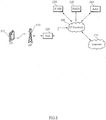
- FIG. 1 is a diagram schematically showing an HPi system.
- the HPi system may include an Access Terminal 100(hereinafter, referred to as "AT"), an Access Point 110(hereinafter, referred to as “AP”), a Packet Access Router 120(hereinafter, referred to as “PAR”), a Packet Data Serving Node 130(hereinafter, referred to as "PDSN”), a Packet Data Gateway Node 140(hereinafter, referred to as "PDGN”), an Authentication Authorization Accounting 150(hereinafter, referred to as "AAA”), an IP network 160 and an internet 170.
- AT Access Terminal 100
- AP Access Point 110
- PAR Packet Access Router 120
- PDSN Packet Data Serving Node 130
- PDGN Packet Data Gateway Node 140
- AAA Authentication Authorization Accounting
- IP network 160 an internet 170.
- the AT 100 refers to a mobile communication terminal which uses a very high speed wireless internet service by connecting with the HPi system and has low power Radio Frequency(hereinafter, referred to as "RF")/Intermediate Frequency(hereinafter, referred to as "IF") module and controller function, a Media Access Control(hereinafter, referred to as "MAC”) frame variable control function depending on service characteristics and radio wave circumstance, a handover function, authentication and encryption functions and etc.
- RF Radio Frequency
- IF Intermediate Frequency
- MAC Media Access Control
- the AP 110 transmits the data received from PAR 120 as a base station of the HPi system, and has a low-power RF/IF module and controller function, OFDMA/TDD packet scheduling and channel multiplex function, an MAC frame variable control function depending on service characteristics and radio wave circumstances, a 50 Mbps high speed traffic real-time control function, a handover function, and etc.
- the AT 100 and the AP 110 have a 50 Mbps packet transmission modulating demodulating function for data transmission, a high packet channel coding function, a real-time modem control function, and etc.
- the PAR 120 is a packet access router which accommodates a number of the AP 110, has a handover control function of AP 100, a handover control function of the PAR 120, a packet routing function, an internet connection function and etc., and further connects with IP network.
- the PDSN 130 relay transmitting and receiving of packet data between an external packet data service server such as the internet 170, etc. and a base station through the IP network 160 and administers the location information data of a mobile communication terminal including the AT 100.
- an external packet data service server such as the internet 170, etc.
- a base station through the IP network 160 and administers the location information data of a mobile communication terminal including the AT 100.
- the PDGN 140 performs a routing which traces and then connects with an external packet data service server of the internet 170, etc. Further, the AAA 150 links the PDSN 130, carries out accounting for a packet data used by the AT 100 and authenticates the connection with the AP 100.
- the IP network 160 connects with the PDSN 130, PDGN 140 and the AAA 150, and then transmits a packet data received from an external packet data service server such as the internet 170, etc. to the AP 100.
- an external packet data service server such as the internet 170, etc.
- a mobile communication service region has been generally divided into a plurality of cells using a frequency reuse concept in order to extend the coverage of a mobile communication network and a Base Station(hereinafter, referred to as "BS") have been installed around the center of each of the cells in order to handle the mobile communication service.
- BS Base Station
- the ratio of a cell is set depending on the strength of a signal or the amount of data traffic. That is, the ratio of a cell is set small in an urban center in which there is much amount of traffic and the ratio of a cell is set large in a suburb in which there is comparatively less amount of data traffic so that the amount of traffic should not exceed the treatment content of the wireless BS handling a corresponding mobile communication service.
- the optical repeater system can solve the problem of the shade of radio wave by allowing a communication channel allocated to a base station to transmit to the shade region of radio waves through an optical transmission scheme using the optical transmission scheme.
- the optical repeater in order to repeat a wireless signal between a base station and a terminal, the optical repeater might be capable of distinguishing an uplink signal from a downlink signal.
- the optical repeater of a mobile communication system must distinguish an uplink signal from a downlink signal by using a duplex when using the FDD scheme.
- it is impossible to distinguish an uplink signal from a downlink signal by using a duplex because it uses the same frequency in order to distinguish an uplink signal from a downlink signal when using the TDD scheme like the HPi system, etc.
- the optical repeater using the TDD scheme is able to distinguish an uplink signal from a downlink signal by using a switch and provide a path for each signal selectively.
- the optical repeater can receive the controlling signal described above.
- the plan is demanded which can distinguish between a downlink signal and an uplink signal in the optical repeater itself and generate a switching timing signal to provide a path of each signal selectively in order to use the optical repeater even in the mobile communication system of the TDD scheme.
- the present invention has been made in view of the above-mentioned problems, and it is as object of the present invention to provide a method and system for generating switching a timing signal for separating a transmitting and receiving signal in an optical repeater of a mobile telecommunication network by using a Time Division Duplex(hereinafter, referred to as "TDD") scheme and an Orthogonal Frequency Division Multiplexing(hereinafter, referred to as "OFDM”) modulation scheme, which transmits a part of a RF signal extracted from a coupler included in a remote of an optical repeater to a switching timing signal generating circuit, locates a frame start position of a RF signal by correlating a reference signal generated in a switching timing signal generating circuit with a RF signal extracted from a coupler, and is capable of transmitting a RF signal by distinguishing between a downlink signal and a uplink signal by using a switching timing signal in a switch when calculating a starting point of a downlink signal and a uplink
- a method for generating a switching timing signal to separate a transmission signal in an optical repeater of a mobile communication system including an AP, an AT and the optical repeater by using a TDD scheme and an OFDM modulation scheme comprising the steps of (a) transmitting an RF signal received from the AP to a remote of the optical repeater via a main donor of the optical repeater; (b) extracting a part of the RF signal in a coupler of the remote, and transmitting the part of the RF signal to a switching timing signal generating circuit of the remote; (c) correlating the RF signal extracted from the coupler with the reference signal generated in the switching timing signal generating circuit; (d) detecting a frame start position of the RF signal by analyzing a correlation result value; (e) calculating starting points of a downlink signal and an uplink signal included in the RF signal on the basis of the frame start position; (f) generating the switching timing signal by using starting point information of the downlink signal and the
- an switching timing signal generating system for separating a RF signal received from an AP and an AT in a optical repeater of a mobile communication network employing a TDD scheme and an OFDM modulation scheme into a downlink signal and an uplink signal
- the switching timing signal generating system comprising a main donor of the optical repeater for converting the RF signal received from the AP to an optical signal, transmitting the optical signal to a remote, converting the optical received from the remoter to a RF signal, and transmitting the RF signal to the AP; a remote of the optical repeater for converting an optical signal received from the main donor to a RF signal, transmitting the RF signal to AT, converting the RF signal received from the AT to an optical signal, and transmitting the optical signal to the main donor; and a switching timing signal generating circuit for extracting a part of the RF signal transmitted to the remote from the main donor, correlating a reference signal generated in itself with an extracted RF signal, detecting a frame start position
- a switching timing signal generating circuit for generating a switching timing signal separating a RF signal received from an AP and an AT in an optical repeater of a mobile communication network employing a TDD scheme and an OFDM modulation scheme into a downlink signal and an uplink signal
- the switching timing generating circuit comprising a divider for receiving an extracted RF signal extracted from a coupler included in a remote of the optical repeater as a part of the RF signal transmitted from a main donor of the optical repeater to the remote, and providing the extracted RF signal for a level detector and a Variable Gain Amplifier(hereinafter, referred to as "VGA"); a level director for measuring a level of the extracted RF signal received from the divider; a VGA for receiving a level value measured at the level detector, and outputting the level of the extracted RF signal; a log-scale amplifier for allowing a variation of the extracted RF signal received from the VGA to convert from a linear scale to a deci
- FIG. 2 is a diagram schematically showing the construction of an optical repeater according to a preferred embodiment of the present invention.
- the optical repeater of the present invention makes both link communication possible by time-dividing the same frequency and distinguishing a downlink signal from an uplink signal due to using a TDD scheme, so that the Optical repeater is allowed to transmit a RF signal by using the same frequency between an AT 100 and an AP 110.
- the optical repeater may include a main donor 200 and a remote 250.
- the main donor of the optical repeater 200 is connected with the AP 110 via a RF cable, receives a RF signal from the AP 110, converts the RF signal to an optical signal by E/O conversion, transmits the optical signal to the remote 250 via optical communication cable, converts the optical signal received from the remote 250 to a RF signal by O/E conversion, and transmits the RF signal to the AP 110 via a RF cable.
- the remote of the optical repeater 250 receives an optical signal from the main donor 200, converts the optical signal to a RF signal by O/E conversion, transmits the RF signal to the AT 100 via an antenna, converts the RF signal received from the AT 100 to an optical signal by E/O conversion, and transmits the optical signal to the main donor 200 via an optical cable.
- the main donor 200 may include a Low Noise Amplifier 205(hereinafter, referred to as "LNA”), an E/O conversion module 210, a Wavelength Division Multiplexer 215 (hereinafter, referred to as "WDM”), an O/E conversion module 220, a High Power Amplifiers 225(hereinafter, referred to as "HPA”) and etc. as internal members.
- the remote 250 may include a WDM, an O/E conversion module 260, a coupler 265, an HPA 270, a switch 275, a LNA 280, an E/O conversion module 285, a switching timing signal generating circuit 290, and etc. as internal members.
- the main donor of the optical repeater 200 can magnify coverage of an optical repeater by being connected with a plurality of remotes 250 through an optical communication cable.
- the main donor 200 may include a signal divider(not illustrated) having multi-channel and a signal coupler. Further, the main donor 200 divides a RF signal received' from the AP 110 by a signal divider, and synthesizes a RF signal received from an HPA 225 and another remote 250's output by a signal coupler.
- the WDM 215 and 255 is an apparatus for being able to separate an optical fiber channel into a plurality of channels and use them as a plural communication channel.
- the WDM 215 and 255 can operate as a wave dividing multiplexer for transmitting several optical waves on one optical fiber.
- the WDM 215 and 255 can operate as a wave diving demultiplexer for dividing several optical wave signals in one optical fiber.
- the E/O conversion modules 210 and 285 can materialize by using a Laser Diode
- O/E conversion modules 220 and 260 can materialize by using a Photo Diode.
- the switching timing signal generating circuit 290 generates a switching timing signal for distinguishing a downlink signal and an uplink signal and controlling a switch when extracted a part of RF signals in a coupler 265, and transmits to the switch 275.
- the construction of the switching timing signal generating circuit 290 is illustrated below in Fig. 3 .
- a RF signal which has been received through a RF cable, is transmitted to a BPF 210 through a LNA 205 of a main donor 200.
- the LNA 205 reduces the noise component of the RF signal, amplifies the signal component, and transmits to the E/O conversion module 210, which converts a RF signal to an optical signal by E/O conversion and transmits the optical signal to a WDM 215.
- the WDM 215 transmits a plurality of optical signals received from the E/O conversion module 210 through an optical communication cable to a remote 250.
- a WDM 255 of a remote 250 divides a plurality of optical signal received from the main donor 200 and transmits to the O/E conversion module 260, which converts optical signals to RF signals by O/E conversion and transmits the RF signals to an HPA 270.
- the HPA 270 amplifies up to an effective power to transmit the RF signals to a switch 275.
- the switch 275 radiates the RF signals to the AT 100 through an antenna.
- the LNA 250 reduces the noise component of the RF signal, amplifies the signal component, and transmits the RF signal to the E/O conversion module 285. Further, the E/O conversion module 285 converts the RF signal to an optical signal by E/O conversion and transmits the optical signal to a WDM 255.
- the WDM 255 transmits the optical signal received from the E/O conversion module 285 through an optical communication cable to a main donor 200.
- a WDM 215 of the main donor 200 divides a plurality of optical signal received from the remote 250 and transmits to the O/E conversion module 220, which converts optical signals to RF signals by O/E conversion and transmits the RF signals to an HPA 225.
- the HPA 225 amplifies up to an effective power to transmit the RF signals to the AP 110 and transmits amplified RF signals to the AP 110 through a RF cable.
- a coupler 265 extracts a part of the RF signals transmitted from the O/E conversion module 220 to the HPA 270, and transmits a part of the RF signals to a switching timing signal generating circuit 290.
- the switching timing signal generating circuit 290 analyzes an extracted RF signal, generates a switching timing signal for transmitting the RF signal, and transmits to the switch 275.
- the switch 275 radiates it to the AT 100 through an antenna.
- the switch 275 blocks a path connected with the HPA 270, and sets up a path to transmit the uplink signal to the LNA 280.
- FIG. 3 is a diagram showing the construction of a switching timing signal generating circuit according to a preferred embodiment of the present invention.
- the switching timing signal generating circuit 290 may include a divider 300, a level director 310, a Variable Gain Amplifier 320 (hereinafter, referred to "VGA"), a log-scale amplifier 330, a pulse generator 340, a comparator 350, a reference pulse generator 360, a phase tuning circuit 370, a timing controller 380, and etc. as internal members.
- VGA Variable Gain Amplifier
- the coupler 265 extracts a part of RF signals, and transmits it to the divider 300. Further, the divider 300 separates the RF signals into the level detector 310 and a VGA 320. Furthermore, the level detector 310 measures a level of the signal and transmits it to the VGA 320. Then, the VGA 320 is received a level value measured in the level detector 310, and always maintains the output signal of the VGA 320 at a steady level.
- the log-scale amplifier 330 lets a variation volume of a signal received from the VGA 320 change from a linear scale into a decibel(dB) scale, and then transmits it to a pulse generator 340.
- the pulse generator 340 generates a pulse waveform signal, and transmits it to the comparator 350 by using the signal received.
- the reference pulse generator 360 generates a reference pulse waveform signal to determine a frame start position of the RF signal after correlating the pulse waveform signal generated in the pulse generator, and transmits the reference pulse waveform signal to the comparator 350.
- the comparator 350 compares a correlation degree of a signal received from the pulse generator with one of a signal received from the reference pulse generator. That is, the comparator 350 correlates the two signals, and transmits the result value to the timing controller 380.
- the timing controller 380 determines a frame start position of the extracted signal by analyzing the received result value, and calculates a starting point of a downlink signal and an uplink signal on the basis of the detected frame start position.
- the timing controller 380 calculates a starting point of a downlink signal and an uplink signal included in a RF signal by using the information of a frame structure when detecting a frame position of a RF signal.
- the timing controller 380 generates a switching timing signal by using the starting point information of a downlink signal and an uplink signal calculated, and transmits it to the switch 275.
- the phase tuning circuit 370 receives the phase information of a pulse waveform generated in the pulse generator 340, and tunes the phase of the reference pulse waveform.
- a switching timing signal separates a RF signal transmitted to the switch 275 into a downlink signal and an uplink signal. Further, when receiving a downlink signal by controlling the received switching timing signal, the switch 275 radiates it to the AT 100 through an antenna. Furthermore, when receiving a uplink signal, the switch 275 blocks a path connected with the HPA 270, and sets up a path to transmit the uplink signal to the LNA 280. Therefore, the switch 275 adjusts a short circuit according to it, and provide each path of a downlink or a uplink signal selectively.
- FIG. 4 is a diagram showing the frame structure of a transmitting and receiving signal by using a TDD scheme and an OFDM modulation scheme.
- a single frame at an HPi system has a length of 5 mesc and is comprised of a down link frame, an up link frame, a Tx/Rx Transition Gap(hereinafter, referred to as "TTG”), a Rx/Tx Transition Gap((hereinafter, referred to as "RTG”), etc.
- TTG Tx/Rx Transition Gap
- RTG Rx/Tx Transition Gap
- the down link is a frame for a downlink signal transmitted to the AT 100 through the optical repeater from the AP 110
- the up link is a frame for an uplink signal transmitted to the AP 110 through the optical repeater from the AT 100.
- the TTG and the RTG is a Guard Time for separating a transmitting time of uplink and downlink, and during this interval, it is not allowed to transmit effective signals including data at the AP 110 and the AT 100.
- the TTG is defined as an interval between the down link and the up link transmitted following it, and during this interval, the AP 110 is changed into a mode for receiving an uplink signal, while the AT 100 is changed into a mode for transmitting an uplink signal.
- the RTG is called an interval between the up link and the down link transmitted following it, and during this interval, the AP 110 is changed into a mode for transmitting a downlink signal, while the AT 100 is changed into a mode for transmitting a downlink signal.
- the down link and the up link which constructs a frame at an HPi system are composed of a plurality of OFDM symbols. Further, the OFDM symbols are comprised of a data symbol, a pilot symbol, and a preamble.
- the data symbol is called a time interval for transmission data, and has a whole time interval which put a time interval (CP time interval) as much as the last Tg from among an effective symbol time interval(Tb) in front of an effective symbol time interval as for the time interval of the data symbol.
- CP time interval time interval
- the reason to set the time interval of data symbol the sum of a CP time interval and an effective symbol time interval is for collecting a signal of multipath by using the OFDM scheme and maintaining quadrature among sub-carriers.
- the preamble has the Ts as for a time interval like the data symbol which is a signal used to synchronize a transmitting timing by signifying a point of time to start transmission of data.
- the ratio of the data symbol comprising a down link and an up link of a frame is capable of supporting the two structures including 16:6 and 13:9, which has been shown in FIG. 4 .
- FIG. 4 shows a frame structure when the ratio of the data symbol of a down link and an up link is 16:6, and (b) shows a frame structure when the ratio of the data symbol of a down link and an up link is 13:9.
- the first OFDM symbol of the down link is a preamble and a pilot symbol is inserted in every three data symbols, and the up link is comprised of the data symbols. Further, the up link is comprised of only data symbols.
- a time interval between the down link and the up link is comprised of TTG and RTG for separating an up/downlink transmitting time.
- the TTG and RTG have integer times of cycle corresponding to a Sampling Frequency(Fs).
- Table 1 shows an individual symbol location of the down link and up link described in FIG. 4 .
- the number of table 1 corresponds to a symbol number designated in each symbols among frames illustrated in FIG. 4 . Further, the resource allocation of time dimension for transmitting data is composed of by the unit of symbols in parenthesis.
- Table 2 shows physical coefficients to the frame structure illustrated in FIG. 4 .
- the frame is illustrated in FIG.4 has the physical coefficients like table 2, each frame has the length of 5 msec described above, when adding up symbols of the up link and the down link, and time intervals of the TTG and the RTG.
- the up link and the down link in the frame are capable of having the asymmetrical structure as described above.
- the down link while it is used a preamble which notifies a point of time to start transmitting data and a pilot symbol which determines a channel, it is possible to use the only preamble without using the pilot symbol.
- the signal may or may not exist according to the condition of communication channel in the data symbol of the up link and the down link
- the switching timing signal generating circuit 290 generates a switching timing signal by determining start position of a down link and an up link after receiving a signal to have the frame structure as described above.
- FIG. 5 is an example screen showing a waveform of a signal when a 10 % probability of data existing in a data symbol of FIG. 4 .
- FIG. 6 is an example screen showing a waveform of reference signal using for correlation in an optical repeater.
- FIG. 7 is an example screen showing a waveform of a signal output in result of correlating the signal illustrated in FIG. 5 and FIG. 6 .
- the coupler 265 of a remote 250 extracts a part of signals and transmits it to a switching timing signal generating circuit 290 when the signal illustrated in FIG. 5 has been transmitted to the remote 250 through a main donor 200 of an optical repeater from the AP 110.
- a switching timing signal generating circuit 290 generates a standard signal illustrated in FIG. 6 .
- the signal waveform illustrated in FIG. 7 is to come by when correlating the standard signal with the received signal illustrated in FIG.5 .
- the reference signal illustrated in FIG. 6 has '1', the signal value from 0 second to 0.015 second to perform correlation in the signal interval in which the received signal exists because the received signal illustrated in FIG. 5 has a signal section from 0 second to 0.015 second
- a starting point of a down link and up link by calculating a time interval set in each symbol of a frame when knowing a start position of a frame because a frame structure including a up link and down link has been defined in advance. That is, a start position of a frame becomes a starting point of a down link because a frame has started from a down link section. Further, a location to add a TTG to a time interval of a down link becomes a starting point of an up link. Therefore, 0.005 second, 0.01 second and 0.015 second having a maximum value in the waveform of FIG. 7 becomes a starting point of each frame respectively. Further, a starting point of an up link and a down link calculated on the basis of this becomes starting points of an uplink signal and a downlink signal.
- the switching timing signal generating circuit 290 controls a switch by generating switching timing signals on the basis of starting points of a downlink signal and an uplink signal. As a result, it is possible to distinguish between a downlink signal and an uplink signal, and provide a transmission path for each signal in the optical repeater.
- FIG. 8 is a flow diagram illustrating a switching timing signal generating process separating transmitting and receiving signals in an optical repeater of a mobile communication network using a TDD scheme and an OFDM modulation scheme according to a preferred embodiment of the present invention.
- a main donor 250 of an optical repeater receives a RF signal transmitted from the AP 110, converts the RF signal to an optical signal, and transmits it to a remote 250 through an optical communication cable(S800).
- the remote 250 converts the received optical signal to a RF signal, and transmits it to the AT 100.
- the coupler 265 located in between the O/E conversion module of the remote 250 and the HPA 270 extracts a part of a RF signal, and transmits it to the switching timing signal generating circuit 290(S802).
- the switching timing signal generating circuit 290 correlates the signal transmitted from the coupler 265 with the reference signal generated in the reference pulse generated of the switching timing signal generating circuit 290(S804). As a result of the correlation, since the location showing the maximum value at the waveform becomes a start location of a frame, it is allowed to determine a start position or a frame by analyzing the waveform by using the result of the correlation(S806).
- the switching timing signal generating circuit 290 calculates a starting point of a downlink signal and uplink signal included in the RF signal on the basis of a frame starting point(S808). When the starting points of the downlink signal and uplink signal are calculated, by using this, the switching timing signal generating circuit 290 generates a switching timing signal for distinguishing the downlink signal from the uplink signal, and transmits it to the switch 275(S810).
- the switch 275 distinguishes the downlink signal from the uplink signal by using the switching timing signal, controls the opening and closing of the switch 275, and then provides path for each signal selectively(S812). Therefore, the optical repeater prevents the switching timing signal from interfering with the downlink signal and uplink signal. Further, the optical repeater repeats the transmission signal between the AP 110 and the AT 100 by transmitting it to the AT 100 in the case of the downlink signal, and transmitting it to the AP 110 in the case of the uplink signal.
- the optical repeater of a mobile communication network using the TDD scheme and the OFDM scheme itself distinguishes between a downlink signal and an uplink signal, generates a switching timing signal to provide a path for each signal selectively, and controls a switch.
Landscapes
- Engineering & Computer Science (AREA)
- Computer Networks & Wireless Communication (AREA)
- Signal Processing (AREA)
- Mobile Radio Communication Systems (AREA)
- Synchronisation In Digital Transmission Systems (AREA)
- Optical Communication System (AREA)
Claims (29)
- Procédé de génération d'un signal de cadencement de commutation utilisé pour séparer des signaux de transmission en signaux de liaison descendante et signaux de liaison montante dans un répéteur optique d'un système de communications mobiles en utilisant un mécanisme de duplexage par répartition dans le temps et un mécanisme de modulation par multiplexage par répartition orthogonale de la fréquence, le système comportant un point d'accès (110), un terminal d'accès (100) et ledit répéteur optique, ledit répéteur optique comprenant un donneur principal (200) et une récepteur distant (250) connectés l'un à l'autre par l'intermédiaire d'un multiplexeur à répartition en longueur d'onde (215, 255), le procédé comprenant les étapes consistant à :(a) transmettre un signal de radiofréquence reçu depuis le point d'accès par l'intermédiaire du donneur principal du répéteur optique au récepteur distant du répéteur optique ;(b) extraire une partie du signal de radiofréquence dans un coupleur (265) du récepteur distant, et transmettre le signal de radiofréquence extrait à un circuit de génération de signal de cadencement de commutation (290) du récepteur distant ;(c) dériver un signal de forme d'onde d'impulsion du signal de radiofréquence extrait ;(d) générer une forme d'onde d'impulsion de référence en fonction d'un préambule du signal de radiofréquence ;(e) corréler le signal de forme d'onde d'impulsion avec la forme d'onde d'impulsion de référence pour générer un signal corrélé, et transmettre le signal corrélé à un contrôleur de cadencement ;(f) détecter une position de début de trame du signal de radiofréquence à partir du signal corrélé ;(g) utiliser la position de début de trame pour calculer des points de départ d'un signal de liaison descendante et d'un signal de liaison montante ;(h) générer un signal de cadencement de commutation en utilisant les points de départ du signal de liaison descendante et du signal de liaison montante, et transmettre le signal de cadencement de commutation à un commutateur (275) du répéteur optique ; et(i) transmettre séparément le signal de liaison descendante et le signal de liaison montante en commandant la commutation au moyen du signal de cadencement de commutation.
- Procédé selon la revendication 1, dans lequel, à l'étape (f), la position correspondant à la valeur de résultat de corrélation maximum est déterminée comme position de début de trame du signal de radiofréquence.
- Procédé selon la revendication 1, dans lequel, à l'étape (i), à la réception d'un signal de liaison descendante en commandant le signal de cadencement de commutation reçu, le commutateur (275) rayonne le signal de liaison descendante vers le terminal d'accès (100), et à la réception d'un signal de liaison montante, le commutateur (275) bloque un chemin connecté à un amplificateur haute puissance (270) du récepteur distant, et établit un chemin pour transmettre le signal de liaison montante à un amplificateur à faible bruit (280) du récepteur distant.
- Procédé selon la revendication 1, dans lequel une trame du signal de radiofréquence comporte une trame de liaison descendante, une trame de liaison montante, un intervalle de transition Tx/Rx et un intervalle de transition Rx/Tx.
- Procédé selon la revendication 4, dans lequel la trame a la longueur de 5 ms suite à l'addition de tous les intervalles de temps de la liaison descendante, de la liaison montante, de l'intervalle de transition Tx/Rx et de l'intervalle de transition Rx/Tx.
- Procédé selon la revendication 5, dans lequel la liaison descendante est une trame d'un signal de liaison descendante transmis depuis le point d'accès par le biais du répéteur optique au terminal d'accès, et la liaison montante est une trame d'un signal de liaison montante transmis depuis le terminal d'accès par le biais du répéteur optique au point d'accès.
- Procédé selon la revendication 6, dans lequel l'intervalle de transition Tx/Rx est un temps de garde pour séparer un temps de transmission de la liaison descendante d'un temps de transmission de la liaison montante, un intervalle entre la liaison descendante et la liaison montante transmises consécutivement, et durant le TGG, le point d'accès est changé en un mode de réception de la liaison montante tandis que le terminal d'accès est changé en un mode de transmission de la liaison descendante.
- Procédé selon la revendication 6, dans lequel l'intervalle de transition Rx/Tx est un temps de garde pour séparer un temps de transmission de la liaison montante d'un temps de transmission de la liaison descendante, un intervalle entre la liaison montante et la liaison descendante transmises consécutivement, et durant le TGG, le point d'accès est changé en un mode de réception de la liaison descendante tandis que le terminal d'accès est changé en un mode de transmission de la liaison montante.
- Procédé selon la revendication 7 ou la revendication 8, dans lequel durant l'intervalle de transition Tx/Rx ou l'intervalle de transition Rx/Tx, aucun du point d'accès et du terminal d'accès ne transmet de signal effectif comportant des données.
- Procédé selon la revendication 6, dans lequel à l'étape (e), la position de début de trame est détectée comme point de départ de la liaison descendante et un emplacement d'un intervalle de transition Tx/Rx plus un intervalle de temps d'une liaison descendante est détecté comme point de départ de la liaison montante, puis le point de départ de la liaison descendante est établi comme point de départ du signal de liaison descendante et le point de départ de la liaison montante est établi comme point de départ du signal de liaison montante.
- Procédé selon la revendication 4, dans lequel la liaison descendante et la liaison montante sont composées d'une pluralité de symboles de multiplexage par répartition orthogonale de la fréquence, les symboles de multiplexage par répartition orthogonale la fréquence comportant un symbole de données, un symbole pilote et un préambule.
- Procédé selon la revendication 11, dans lequel un rapport du symbole de données comprenant la liaison descendante et la liaison montante de la trame a une structure asymétrique de 16:6 ou 13:9.
- Procédé selon la revendication 11, dans lequel le premier symbole de multiplexage par répartition orthogonale de la fréquence de la liaison descendante est le préambule et un symbole pilote est inséré dans tous les trois symboles de données, et la liaison montante est composée des symboles de données.
- Procédé selon la revendication 11, dans lequel le premier symbole de multiplexage par répartition orthogonale de la fréquence de la liaison descendante est le préambule et le multiplexage par répartition orthogonale de la fréquence restant est composé des symboles de données, et la liaison montante est composée des symboles de données.
- Procédé selon la revendication 11, dans lequel l'intervalle de temps du symbole de données correspond un intervalle de temps Ts = Tg + Tb, lequel est le dernier Tg à partir d'un intervalle de temps de symbole effectif (Tb) plus un intervalle de temps de symbole effectif.
- Procédé selon la revendication 15, dans lequel le préambule comprend Ts comme intervalle de temps, et est utilisé pour synchroniser un cadencement de transmission en notifiant un instant de temps auquel commencer la transmission de données.
- Procédé selon la revendication 15, dans lequel le symbole pilote comprend Tp = Tb/2 + Tg comme intervalle de temps, et est utilisé pour déterminer qu'un canal de communication est une liaison descendante ou une liaison montante par son insertion au milieu du symbole de données.
- Système de génération d'un signal de cadencement de commutation utilisé pour séparer un signal de radiofréquence en un signal de liaison descendante et un signal de liaison montante dans un répéteur optique d'un réseau de communications mobiles comportant un point d'accès (110) et un terminal d'accès (100) employant un mécanisme de duplexage par répartition dans le temps et un mécanisme de modulation par multiplexage par répartition orthogonale de la fréquence, le système de génération de signal de cadencement de commutation comprenant un donneur principal (200) situé dans le répéteur optique pour convertir le signal RF reçu depuis le point d'accès en un signal optique, transmettre le signal optique à un récepteur distant (250) situé dans le répéteur optique, convertir le signal optique reçu depuis le récepteur distant en un signal de radiofréquence, et transmettre le signal de radiofréquence au point d'accès ;
un récepteur distant (250) situé dans le répéteur optique pour convertir un signal optique reçu du donneur principal en un signal de radiofréquence, transmettre le signal RF au terminal d'accès, convertir le signal RF reçu depuis le terminal d'accès en un signal optique, et transmettre le signal optique au donneur principal, extraire une partie du signal de radiofréquence dans un coupleur du récepteur distant, et transmettre le signal de radiofréquence extrait à un circuit de génération de signal de cadencement de commutation du récepteur distant ;
un circuit de génération de signal de cadencement de commutation (290) pour dériver un signal de forme d'onde d'impulsion du signal de radiofréquence extrait,
générer une forme d'onde d'impulsion de référence en fonction d'un préambule du signal de radiofréquence,
corréler le signal de forme d'onde d'impulsion avec la forme d'onde d'impulsion de référence pour générer un signal corrélé, et transmettre le signal corrélé à un contrôleur de cadencement, détecter une position de début de trame du signal de radiofréquence à partir du signal corrélé, utiliser la position de début de trame pour calculer des points de départ d'un signal de liaison descendante et d'un signal de liaison montante,
générer un signal de cadencement de commutation en utilisant des informations de point de départ du signal de liaison descendante et du signal de liaison montante, et transmettre le signal de cadencement de commutation à un commutateur. - Système de génération de signal de cadencement de commutation selon la revendication 18, dans lequel le point d'accès est adapté pour transmettre le signal de radiofréquence au terminal d'accès par le biais du répéteur optique et est adapté pour recevoir le signal de radiofréquence transmis par le terminal d'accès par le biais du répéteur optique pendant que le terminal d'accès est adapté pour recevoir le signal de radiofréquence transmis par le point d'accès par le biais du répéteur optique et est adapté pour transmettre le signal RF au point d'accès par le biais du répéteur optique.
- Système de génération de signal de cadencement de commutation selon la revendication 18, dans lequel le donneur principal du répéteur optique est adapté pour transmettre le signal de radiofréquence au point d'accès par le biais d'un câble radiofréquence.
- Système de génération de signal de cadencement de commutation selon la revendication 18 ou la revendication 19, dans lequel le donneur principal du répéteur optique comporte un amplificateur à faible bruit, un module de conversion E/O, un multiplexeur par répartition en longueur d'onde WDM (215), un module de conversion O/E, un amplificateur haute puissance.
- Système de génération de signal de cadencement de commutation selon la revendication 21, dans lequel le donneur principal est connecté au récepteur distant d'une pluralité de répéteurs optiques par le biais d'un câble de communication optique.
- Système de génération de signal de cadencement de commutation selon la revendication 22, dans lequel le donneur principal comporte un diviseur de signal ayant de multiples canaux et un coupleur de signal.
- Système de génération de signal de cadencement de commutation selon la revendication 18 ou la revendication 19, dans lequel le récepteur distant du répéteur optique comporte un multiplexeur par répartition en longueur d'onde WDM, un module de conversion O/E, un amplificateur de puissance, un commutateur, un amplificateur à faible bruit et un module de conversion E/O.
- Système de génération de signal de cadencement de commutation selon la revendication 24, comprenant en outre un coupleur situé entre le module de conversion O/E et l'amplificateur de puissance, pour extraire une partie du signal radiofréquence transmis depuis le module de conversion O/E à l'amplificateur haute puissance, et transmettre le signal de radiofréquence au circuit de génération de signal de cadencement de commutation.
- Système de génération de signal de cadencement de commutation selon la revendication 25, dans lequel le circuit de génération de signal de cadencement de commutation situé à l'intérieur du récepteur distant du répéteur optique est adapté pour recevoir le signal de radiofréquence extrait du coupleur, générer le signal de cadencement de communication, et transmettre le signal de cadencement au commutateur.
- Système de génération de signal de cadencement de commutation selon la revendication 18, dans lequel le circuit de génération de signal de cadencement de commutation (290) comprend en outre :un diviseur (300) destiné à recevoir un signal de radiofréquence RF extrait d'un coupleur (265) inclus dans le récepteur distant (250) du répéteur optique en tant que partie du signal de radiofréquence transmis par le donneur principal (200) du répéteur optique au récepteur distant, et fournir le signal RF extrait à un détecteur de niveau et un amplificateur à gain variable VGA (320) ;un détecteur de niveau (310) destiné à mesurer un niveau du signal de radiofréquence extrait reçu du diviseur ;un amplificateur à gain variable VGA (320) destiné à recevoir une valeur de niveau mesurée par le détecteur de niveau, et produire en sortie le niveau du signal RF extrait ; un amplificateur d'échelle logarithmique (330) pour permettre une variation du signal de radiofréquence extrait reçu depuis le VGA pour convertir une échelle linéaire en une échelle de décibels (dB), et transmettre un signal de radiofréquence extrait converti à un générateur d'impulsion (340) ;un générateur d'impulsion (340) destiné à générer un signal de forme d'onde d'impulsion en utilisant le signal de radiofréquence extrait reçu de l'amplificateur d'échelle logarithmique, et transmettre le signal de forme d'onde d'impulsion à un comparateur (350) ;un générateur d'impulsion de référence (360) destiné à générer un signal de forme d'onde d'impulsion de référence destiné à être utilisé dans la détermination d'une position de début de trame du signal de radiofréquence extrait après la corrélation du signal de forme d'onde d'impulsion généré dans le générateur d'impulsion et transmettre le signal de forme d'onde d'impulsion de référence au comparateur ;le comparateur (350) destiné à corréler le signal de forme d'onde d'impulsion reçu du générateur d'impulsion avec le signal de forme d'onde d'impulsion de référence reçu depuis le générateur d'impulsion de référence ;un contrôleur de cadencement (380) destiné à déterminer une position de début de trame du signal de radiofréquence extrait en analysant une valeur de résultat de corrélation, calculant un point de départ du signal de liaison descendante et du signal de liaison montante inclus dans le signal de radiofréquence en fonction de la position de début de trame, et générant un signal de cadencement de commutation en utilisant les informations de point de début du signal de liaison descendante et du signal de liaison montante, et transmettant le signal de cadencement de commutation au commutateur (275) du répéteur optique ; etun circuit d'accord de phase (370) pour recevoir une information de phase du signal de forme d'onde d'impulsion généré dans le générateur d'impulsion, et accorder la phase du signal de forme d'onde d'impulsion de référence.
- Système de génération de signal de cadencement de commutation selon la revendication 27, dans lequel le contrôleur de cadencement est adapté pour détecter une position de début de trame du signal de radiofréquence extrait comme position où la valeur du résultat de corrélation est maximum en analysant la valeur du résultat de corrélation.
- Système de génération de signal de cadencement de commutation selon la revendication 27, dans lequel le signal de cadencement de commutation est adapté pour séparer le signal de radiofréquence transmis au commutateur en un signal de liaison descendante et un signal de liaison montante, et est adapté pour commander le commutateur afin de rayonner le signal de liaison descendante vers le terminal d'accès (100) par le biais d'une antenne lors de la réception du signal de liaison descendante, et est adapté pour commander le commutateur afin de transmettre le signal de liaison montante à l'amplificateur à faible bruit du récepteur distant à la réception du signal de liaison montante par le biais de l'antenne.
Applications Claiming Priority (2)
| Application Number | Priority Date | Filing Date | Title |
|---|---|---|---|
| KR1020040059582A KR100590486B1 (ko) | 2004-07-29 | 2004-07-29 | Tdd 방식과 ofdm 변조 방식을 이용하는 이동통신망의 광중계기에서 전송 신호를 분리하는 스위칭타이밍 신호 생성 방법 및 시스템 |
| PCT/KR2005/002484 WO2006011778A1 (fr) | 2004-07-29 | 2005-07-29 | Procede et systeme pour la generation de commutation de signal de synchronisation pour la separation de signal de transmission et de reception dans un repeteur optique de reseau de telecommunication au moyen de duplex a repartition dans le temps et de modulation par multiplexage frequentiel |
Publications (3)
| Publication Number | Publication Date |
|---|---|
| EP1771987A1 EP1771987A1 (fr) | 2007-04-11 |
| EP1771987A4 EP1771987A4 (fr) | 2012-12-05 |
| EP1771987B1 true EP1771987B1 (fr) | 2017-01-18 |
Family
ID=35786476
Family Applications (1)
| Application Number | Title | Priority Date | Filing Date |
|---|---|---|---|
| EP05773982.3A Expired - Lifetime EP1771987B1 (fr) | 2004-07-29 | 2005-07-29 | Procede et systeme pour la generation de commutation de signal de synchronisation pour la separation de signal de transmission et de reception dans un repeteur optique de reseau de telecommunication au moyen de duplex a repartition dans le temps et de modulation par multiplexage frequentiel |
Country Status (6)
| Country | Link |
|---|---|
| US (1) | US7899084B2 (fr) |
| EP (1) | EP1771987B1 (fr) |
| JP (1) | JP4435231B2 (fr) |
| KR (1) | KR100590486B1 (fr) |
| CN (1) | CN101019398B (fr) |
| WO (1) | WO2006011778A1 (fr) |
Families Citing this family (163)
| Publication number | Priority date | Publication date | Assignee | Title |
|---|---|---|---|---|
| US6904079B2 (en) * | 2000-02-08 | 2005-06-07 | Ipr Licensing, Inc. | Access channel structure for wireless communication system |
| DE60322541D1 (de) | 2002-06-21 | 2008-09-11 | Qualcomm Inc | Zwischenverstärker für drahtlose lokale netzwerke |
| US8885688B2 (en) | 2002-10-01 | 2014-11-11 | Qualcomm Incorporated | Control message management in physical layer repeater |
| KR100664583B1 (ko) * | 2004-08-16 | 2007-01-04 | 주식회사 쏠리테크 | 휴대인터넷 서비스에서 기지국과 중계기의 네트워크 시스템 |
| JP5107997B2 (ja) * | 2006-03-31 | 2012-12-26 | クゥアルコム・インコーポレイテッド | WiMAXシステム内の動作のための機能強化した物理層中継器 |
| KR100762637B1 (ko) * | 2006-05-03 | 2007-10-01 | 삼성전자주식회사 | Tdd 방식의 무선 시스템 신호 전송을 위한 단일 파장양방향 rof 링크 장치 |
| US7495560B2 (en) | 2006-05-08 | 2009-02-24 | Corning Cable Systems Llc | Wireless picocellular RFID systems and methods |
| US8472767B2 (en) | 2006-05-19 | 2013-06-25 | Corning Cable Systems Llc | Fiber optic cable and fiber optic cable assembly for wireless access |
| US20070292136A1 (en) | 2006-06-16 | 2007-12-20 | Michael Sauer | Transponder for a radio-over-fiber optical fiber cable |
| WO2008034354A1 (fr) * | 2006-08-07 | 2008-03-27 | Huawei Technologies Co., Ltd. | Système, appareil et procédé pour transmettre une signalisation d'abonné numérique |
| US7627250B2 (en) | 2006-08-16 | 2009-12-01 | Corning Cable Systems Llc | Radio-over-fiber transponder with a dual-band patch antenna system |
| KR100799679B1 (ko) * | 2006-08-30 | 2008-01-30 | 주식회사 휴텍이일 | 시분할 및 주파수분할 방식의 마이크로웨이브중계기시스템 |
| KR100819257B1 (ko) * | 2006-08-31 | 2008-04-02 | 삼성전자주식회사 | 전송시간을 제어하기 위한 radio over fiber시스템 및 방법 |
| US7787823B2 (en) | 2006-09-15 | 2010-08-31 | Corning Cable Systems Llc | Radio-over-fiber (RoF) optical fiber cable system with transponder diversity and RoF wireless picocellular system using same |
| JP5199261B2 (ja) | 2006-09-21 | 2013-05-15 | クゥアルコム・インコーポレイテッド | リピータの間の振動を緩和するための方法および装置 |
| US7848654B2 (en) | 2006-09-28 | 2010-12-07 | Corning Cable Systems Llc | Radio-over-fiber (RoF) wireless picocellular system with combined picocells |
| KR20090074812A (ko) * | 2006-10-26 | 2009-07-07 | 퀄컴 인코포레이티드 | 빔 형성기를 이용한 다중 입력 다중 출력을 위한 중계기 기술 |
| KR100770883B1 (ko) * | 2006-11-14 | 2007-10-26 | 삼성전자주식회사 | TDD 방식의 Radio Over Fiber 시스템 및전송시간 제어 방법 |
| CN101192875B (zh) * | 2006-11-27 | 2011-05-25 | 上海无线通信研究中心 | 用于通用陆地无线接入系统的上行正交参考信号分配方法 |
| KR100842533B1 (ko) * | 2006-12-13 | 2008-07-01 | 삼성전자주식회사 | 시분할 듀플렉싱 방식 무선광섬유 링크 장치 |
| KR100842534B1 (ko) | 2006-12-14 | 2008-07-01 | 삼성전자주식회사 | Tdd 방식의 광중계기에서 전송 신호를 분리하는 스위치제어 신호 생성 방법 및 시스템 |
| US8873585B2 (en) | 2006-12-19 | 2014-10-28 | Corning Optical Communications Wireless Ltd | Distributed antenna system for MIMO technologies |
| KR101306726B1 (ko) * | 2006-12-22 | 2013-09-10 | 엘지전자 주식회사 | 이동통신 시스템에서의 참조 신호용 심볼 배치 방법, 및이에 따른 서브 프레임을 이용한 신호 송수신 방법 |
| KR100856196B1 (ko) | 2007-01-03 | 2008-09-03 | 삼성전자주식회사 | Tdd 방식의 광중계기에서 리모트 제어 방법 및 시스템 |
| US8111998B2 (en) | 2007-02-06 | 2012-02-07 | Corning Cable Systems Llc | Transponder systems and methods for radio-over-fiber (RoF) wireless picocellular systems |
| KR100866217B1 (ko) | 2007-03-28 | 2008-10-30 | 삼성전자주식회사 | 시분할 듀플렉싱 시스템에서 시스템 지연 시간과 프레임길이를 구성하는 방법 및 장치 |
| KR20080093746A (ko) * | 2007-04-18 | 2008-10-22 | 삼성전자주식회사 | 저잡음 증폭기를 상하향 공용으로 구성하는 시분할 이중화방식의 원격 스테이션 및 이를 이용한 유선 중계 방법 |
| US20100054746A1 (en) | 2007-07-24 | 2010-03-04 | Eric Raymond Logan | Multi-port accumulator for radio-over-fiber (RoF) wireless picocellular systems |
| US7860406B2 (en) * | 2007-09-14 | 2010-12-28 | Alcatel-Lucent Usa Inc. | PMD insensitive direct-detection optical OFDM systems using self-polarization diversity |
| US8175459B2 (en) | 2007-10-12 | 2012-05-08 | Corning Cable Systems Llc | Hybrid wireless/wired RoF transponder and hybrid RoF communication system using same |
| WO2009052420A2 (fr) * | 2007-10-17 | 2009-04-23 | Zte U.S.A., Inc. | Structure de trame ofdm/ofdma pour systèmes de communication |
| US8369301B2 (en) | 2007-10-17 | 2013-02-05 | Zte (Usa) Inc. | OFDM/OFDMA frame structure for communication systems |
| KR101450875B1 (ko) | 2007-11-15 | 2014-10-24 | 삼성전자주식회사 | 광 릴레이를 고려한 무선시스템에서 tdd 컨트롤 신호의결정 방법 |
| WO2009081376A2 (fr) | 2007-12-20 | 2009-07-02 | Mobileaccess Networks Ltd. | Extension de services et d'applications d'extérieur à des zones fermées |
| DE102008017881B9 (de) * | 2008-04-09 | 2012-11-08 | Andrew Wireless Systems Gmbh | TDD-Repeater für ein Drahtlos-Netz und Verfahren zum Betrieb eines solchen Repeaters |
| WO2009149461A2 (fr) * | 2008-06-06 | 2009-12-10 | Power Tagging Technologies | Système électrique intelligent et procédé pour sa mise en oeuvre |
| EP2311211B1 (fr) * | 2008-06-20 | 2011-12-28 | Nokia Siemens Networks Oy | Système de multiplexage de sous-porteuse |
| AU2010210766A1 (en) | 2009-02-03 | 2011-09-15 | Corning Cable Systems Llc | Optical fiber-based distributed antenna systems, components, and related methods for monitoring and configuring thereof |
| US9673904B2 (en) | 2009-02-03 | 2017-06-06 | Corning Optical Communications LLC | Optical fiber-based distributed antenna systems, components, and related methods for calibration thereof |
| EP2394379B1 (fr) | 2009-02-03 | 2016-12-28 | Corning Optical Communications LLC | Systèmes et composants d'antennes distribuées à base de fibres optiques, et procédés de calibrage associés |
| US8548330B2 (en) | 2009-07-31 | 2013-10-01 | Corning Cable Systems Llc | Sectorization in distributed antenna systems, and related components and methods |
| KR101752409B1 (ko) * | 2009-08-25 | 2017-06-29 | 엘지전자 주식회사 | 무선 통신 시스템에서 제어 정보 송수신 방법 |
| US8280259B2 (en) | 2009-11-13 | 2012-10-02 | Corning Cable Systems Llc | Radio-over-fiber (RoF) system for protocol-independent wired and/or wireless communication |
| US8886755B1 (en) | 2009-12-09 | 2014-11-11 | Marvell International Ltd. | Method and apparatus for facilitating simultaneous transmission from multiple stations |
| US8275265B2 (en) | 2010-02-15 | 2012-09-25 | Corning Cable Systems Llc | Dynamic cell bonding (DCB) for radio-over-fiber (RoF)-based networks and communication systems and related methods |
| US20110268446A1 (en) | 2010-05-02 | 2011-11-03 | Cune William P | Providing digital data services in optical fiber-based distributed radio frequency (rf) communications systems, and related components and methods |
| US9525488B2 (en) | 2010-05-02 | 2016-12-20 | Corning Optical Communications LLC | Digital data services and/or power distribution in optical fiber-based distributed communications systems providing digital data and radio frequency (RF) communications services, and related components and methods |
| US9444514B2 (en) | 2010-05-28 | 2016-09-13 | Cohere Technologies, Inc. | OTFS methods of data channel characterization and uses thereof |
| US9071286B2 (en) | 2011-05-26 | 2015-06-30 | Cohere Technologies, Inc. | Modulation and equalization in an orthonormal time-frequency shifting communications system |
| US9071285B2 (en) | 2011-05-26 | 2015-06-30 | Cohere Technologies, Inc. | Modulation and equalization in an orthonormal time-frequency shifting communications system |
| US11943089B2 (en) | 2010-05-28 | 2024-03-26 | Cohere Technologies, Inc. | Modulation and equalization in an orthonormal time-shifting communications system |
| US10667148B1 (en) | 2010-05-28 | 2020-05-26 | Cohere Technologies, Inc. | Methods of operating and implementing wireless communications systems |
| US10681568B1 (en) | 2010-05-28 | 2020-06-09 | Cohere Technologies, Inc. | Methods of data channel characterization and uses thereof |
| US9130638B2 (en) | 2011-05-26 | 2015-09-08 | Cohere Technologies, Inc. | Modulation and equalization in an orthonormal time-frequency shifting communications system |
| EP2606707A1 (fr) | 2010-08-16 | 2013-06-26 | Corning Cable Systems LLC | Grappes d'antennes distantes, et systèmes, composants et procédés associés adaptés pour prendre en charge une propagation de signaux de données numériques entre des unités d'antennes distantes |
| CN102386954B (zh) * | 2010-09-03 | 2014-05-07 | 华为技术有限公司 | 数据传输方法、接入点设备及终端 |
| US9252874B2 (en) | 2010-10-13 | 2016-02-02 | Ccs Technology, Inc | Power management for remote antenna units in distributed antenna systems |
| CN203504582U (zh) | 2011-02-21 | 2014-03-26 | 康宁光缆系统有限责任公司 | 一种分布式天线系统及用于在其中分配电力的电源装置 |
| US20120265355A1 (en) | 2011-04-15 | 2012-10-18 | Power Tagging Technologies, Inc. | System and method for single and multizonal optimization of utility services delivery and utilization |
| CN103548290B (zh) | 2011-04-29 | 2016-08-31 | 康宁光缆系统有限责任公司 | 判定分布式天线系统中的通信传播延迟及相关组件、系统与方法 |
| WO2012148940A1 (fr) | 2011-04-29 | 2012-11-01 | Corning Cable Systems Llc | Systèmes, procédés et dispositifs pour augmenter la puissance radiofréquence (rf) dans systèmes d'antennes distribuées |
| US9059842B2 (en) | 2011-06-09 | 2015-06-16 | Astrolink International Llc | System and method for grid based cyber security |
| WO2013020053A1 (fr) | 2011-08-03 | 2013-02-07 | Power Tagging Technologies, Inc. | Système et procédés permettant de synchroniser des dispositifs périphériques sur des canaux sans détection de porteuse |
| CN102281229B (zh) * | 2011-08-24 | 2017-12-05 | 中兴通讯股份有限公司 | 一种通信系统中转换间隔的配置方法及装置 |
| TWI462514B (zh) * | 2011-09-29 | 2014-11-21 | Inst Information Industry | 分時多工正交分頻多工分佈式天線系統、基地台及遠端存取組件 |
| WO2013148986A1 (fr) | 2012-03-30 | 2013-10-03 | Corning Cable Systems Llc | Réduction d'un brouillage lié à la position dans des systèmes d'antennes distribuées fonctionnant selon une configuration à entrées multiples et à sorties multiples (mimo), et composants, systèmes et procédés associés |
| EP2842245A1 (fr) | 2012-04-25 | 2015-03-04 | Corning Optical Communications LLC | Architectures de système d'antenne distribué |
| US10469215B2 (en) | 2012-06-25 | 2019-11-05 | Cohere Technologies, Inc. | Orthogonal time frequency space modulation system for the Internet of Things |
| US9929783B2 (en) * | 2012-06-25 | 2018-03-27 | Cohere Technologies, Inc. | Orthogonal time frequency space modulation system |
| US10090972B2 (en) | 2012-06-25 | 2018-10-02 | Cohere Technologies, Inc. | System and method for two-dimensional equalization in an orthogonal time frequency space communication system |
| US10411843B2 (en) | 2012-06-25 | 2019-09-10 | Cohere Technologies, Inc. | Orthogonal time frequency space communication system compatible with OFDM |
| WO2014024192A1 (fr) | 2012-08-07 | 2014-02-13 | Corning Mobile Access Ltd. | Distribution de services de gestion multiplexés par répartition dans le temps (tdm) dans un système d'antennes distribuées, et composants, systèmes et procédés associés |
| US9455784B2 (en) | 2012-10-31 | 2016-09-27 | Corning Optical Communications Wireless Ltd | Deployable wireless infrastructures and methods of deploying wireless infrastructures |
| US9077508B2 (en) * | 2012-11-15 | 2015-07-07 | Mitsubishi Electric Research Laboratories, Inc. | Adaptively coding and modulating signals transmitted via nonlinear channels |
| CN105308876B (zh) | 2012-11-29 | 2018-06-22 | 康宁光电通信有限责任公司 | 分布式天线系统中的远程单元天线结合 |
| US9647758B2 (en) | 2012-11-30 | 2017-05-09 | Corning Optical Communications Wireless Ltd | Cabling connectivity monitoring and verification |
| US10097240B2 (en) | 2013-02-19 | 2018-10-09 | Astrolink International, Llc | System and method for inferring schematic and topological properties of an electrical distribution grid |
| US9438312B2 (en) | 2013-06-06 | 2016-09-06 | Astrolink International Llc | System and method for inferring schematic relationships between load points and service transformers |
| EP3008828B1 (fr) | 2013-06-12 | 2017-08-09 | Corning Optical Communications Wireless Ltd. | Duplexage par répartition temporelle (tdd) dans des systèmes de communication répartis, comprenant des systèmes d'antenne répartis (das) |
| WO2014199384A1 (fr) | 2013-06-12 | 2014-12-18 | Corning Optical Communications Wireless, Ltd. | Coupleur directif optique a commande en tension |
| MX357831B (es) | 2013-06-13 | 2018-07-26 | Astrolink Int Llc | Perdidas no tecnicas en una rejilla electrica publica. |
| WO2014201410A1 (fr) | 2013-06-13 | 2014-12-18 | Astrolink International Llc C/O Lockheed Martin Corporation | Déduction de la ligne d'alimentation et de la phase d'alimentation d'un émetteur |
| US9247543B2 (en) | 2013-07-23 | 2016-01-26 | Corning Optical Communications Wireless Ltd | Monitoring non-supported wireless spectrum within coverage areas of distributed antenna systems (DASs) |
| US9661781B2 (en) | 2013-07-31 | 2017-05-23 | Corning Optical Communications Wireless Ltd | Remote units for distributed communication systems and related installation methods and apparatuses |
| US9385810B2 (en) | 2013-09-30 | 2016-07-05 | Corning Optical Communications Wireless Ltd | Connection mapping in distributed communication systems |
| CN105874876B (zh) | 2013-10-30 | 2019-05-10 | 安德鲁无线系统有限公司 | 用于利用时分双工的分布式天线系统的切换子系统 |
| US9825678B2 (en) | 2013-11-26 | 2017-11-21 | Marvell World Trade Ltd. | Uplink multi-user multiple input multiple output for wireless local area network |
| WO2015081269A1 (fr) | 2013-11-27 | 2015-06-04 | Marvell Semiconductor, Inc. | Sondage et allocation de blocs de tonalité pour un accès multiple par répartition orthogonale de fréquence (ofdma) dans des réseaux locaux sans fil |
| WO2015081187A1 (fr) | 2013-11-27 | 2015-06-04 | Marvell Semiconductor, Inc. | Formation de faisceau à entrée multiple sortie multiple multi-utilisateur de liaison montante |
| US9178635B2 (en) | 2014-01-03 | 2015-11-03 | Corning Optical Communications Wireless Ltd | Separation of communication signal sub-bands in distributed antenna systems (DASs) to reduce interference |
| US9775123B2 (en) | 2014-03-28 | 2017-09-26 | Corning Optical Communications Wireless Ltd. | Individualized gain control of uplink paths in remote units in a distributed antenna system (DAS) based on individual remote unit contribution to combined uplink power |
| JP6430535B2 (ja) | 2014-05-02 | 2018-11-28 | マーベル ワールド トレード リミテッド | 方法、機器、および第1通信デバイス |
| US9357551B2 (en) | 2014-05-30 | 2016-05-31 | Corning Optical Communications Wireless Ltd | Systems and methods for simultaneous sampling of serial digital data streams from multiple analog-to-digital converters (ADCS), including in distributed antenna systems |
| US9525472B2 (en) | 2014-07-30 | 2016-12-20 | Corning Incorporated | Reducing location-dependent destructive interference in distributed antenna systems (DASS) operating in multiple-input, multiple-output (MIMO) configuration, and related components, systems, and methods |
| JP6352729B2 (ja) * | 2014-08-26 | 2018-07-04 | 株式会社東芝 | レピータシステム、レピータ装置及びタイミング信号生成方法 |
| US9730228B2 (en) | 2014-08-29 | 2017-08-08 | Corning Optical Communications Wireless Ltd | Individualized gain control of remote uplink band paths in a remote unit in a distributed antenna system (DAS), based on combined uplink power level in the remote unit |
| US9602210B2 (en) | 2014-09-24 | 2017-03-21 | Corning Optical Communications Wireless Ltd | Flexible head-end chassis supporting automatic identification and interconnection of radio interface modules and optical interface modules in an optical fiber-based distributed antenna system (DAS) |
| US9420542B2 (en) | 2014-09-25 | 2016-08-16 | Corning Optical Communications Wireless Ltd | System-wide uplink band gain control in a distributed antenna system (DAS), based on per band gain control of remote uplink paths in remote units |
| US10659163B2 (en) | 2014-09-25 | 2020-05-19 | Corning Optical Communications LLC | Supporting analog remote antenna units (RAUs) in digital distributed antenna systems (DASs) using analog RAU digital adaptors |
| AU2015338943B2 (en) | 2014-10-30 | 2019-09-12 | Dominion Energy Technologies, Inc. | System and methods for assigning slots and resolving slot conflicts in an electrical distribution grid |
| CA2964393A1 (fr) | 2014-10-30 | 2016-05-06 | Dominion Energy Technologies, Inc. | Systeme, procede, et appareil de positionnement de reseau electrique |
| WO2016071902A1 (fr) | 2014-11-03 | 2016-05-12 | Corning Optical Communications Wireless Ltd. | Antennes planes monopôles multibandes configurées pour faciliter une isolation radiofréquence (rf) améliorée dans un système d'antennes entrée multiple sortie multiple (mimo) |
| WO2016075696A1 (fr) | 2014-11-13 | 2016-05-19 | Corning Optical Communications Wireless Ltd. | Systèmes d'antennes distribuées (das) analogiques prenant en charge une distribution de signaux de communications numériques interfacés provenant d'une source de signaux numériques et de signaux de communications radiofréquences (rf) analogiques |
| US9729267B2 (en) | 2014-12-11 | 2017-08-08 | Corning Optical Communications Wireless Ltd | Multiplexing two separate optical links with the same wavelength using asymmetric combining and splitting |
| WO2016098111A1 (fr) | 2014-12-18 | 2016-06-23 | Corning Optical Communications Wireless Ltd. | Modules d'interface numérique-analogique (daim) pour une distribution flexible de signaux de communications numériques et/ou analogiques dans des systèmes étendus d'antennes distribuées analogiques (das) |
| EP3235336A1 (fr) | 2014-12-18 | 2017-10-25 | Corning Optical Communications Wireless Ltd. | Modules d'interface numérique (dim) pour une distribution flexible de signaux de communication numériques et/ou analogiques dans des réseaux d'antennes distribuées (das) analogiques étendus |
| US20160249365A1 (en) | 2015-02-19 | 2016-08-25 | Corning Optical Communications Wireless Ltd. | Offsetting unwanted downlink interference signals in an uplink path in a distributed antenna system (das) |
| US9681313B2 (en) | 2015-04-15 | 2017-06-13 | Corning Optical Communications Wireless Ltd | Optimizing remote antenna unit performance using an alternative data channel |
| CN107925434B (zh) | 2015-05-11 | 2021-02-05 | 凝聚技术公司 | 用于数据的辛正交时频移位调制和传输的系统和方法 |
| US10090973B2 (en) | 2015-05-11 | 2018-10-02 | Cohere Technologies, Inc. | Multiple access in an orthogonal time frequency space communication system |
| US10574317B2 (en) | 2015-06-18 | 2020-02-25 | Cohere Technologies, Inc. | System and method for providing wireless communication services using configurable broadband infrastructure shared among multiple network operators |
| US10404514B2 (en) | 2015-06-27 | 2019-09-03 | Cohere Technologies, Inc. | Orthogonal time frequency space communication system compatible with OFDM |
| US10693581B2 (en) | 2015-07-12 | 2020-06-23 | Cohere Technologies, Inc. | Orthogonal time frequency space modulation over a plurality of narrow band subcarriers |
| US9948349B2 (en) | 2015-07-17 | 2018-04-17 | Corning Optical Communications Wireless Ltd | IOT automation and data collection system |
| EP3342068A1 (fr) * | 2015-08-24 | 2018-07-04 | Telefonaktiebolaget LM Ericsson (PUBL) | Commande d'un émetteur optique dans un système radio sur fibre |
| CN108770382B (zh) | 2015-09-07 | 2022-01-14 | 凝聚技术公司 | 使用正交时间频率空间调制的多路存取的方法 |
| US10560214B2 (en) | 2015-09-28 | 2020-02-11 | Corning Optical Communications LLC | Downlink and uplink communication path switching in a time-division duplex (TDD) distributed antenna system (DAS) |
| US9647752B2 (en) | 2015-10-13 | 2017-05-09 | Telefonaktiebolaget Lm Ericsson (Publ) | Antenna switch control method for analog radio over fiber systems |
| US11038733B2 (en) | 2015-11-18 | 2021-06-15 | Cohere Technologies, Inc. | Orthogonal time frequency space modulation techniques |
| WO2017100666A1 (fr) | 2015-12-09 | 2017-06-15 | Cohere Technologies | Emballage pilote utilisant des fonctions orthogonales complexes |
| US10666314B2 (en) | 2016-02-25 | 2020-05-26 | Cohere Technologies, Inc. | Reference signal packing for wireless communications |
| WO2017165697A1 (fr) | 2016-03-23 | 2017-09-28 | Cohere Technologies | Traitement côté récepteur des signaux modulés dans l'espace de fréquence temporelle orthogonale |
| WO2017173160A1 (fr) | 2016-03-31 | 2017-10-05 | Cohere Technologies | Acquisition de canal à l'aide d'un signal pilote à modulation orthogonale dans le temps, la fréquence et l'espace |
| US10236924B2 (en) | 2016-03-31 | 2019-03-19 | Corning Optical Communications Wireless Ltd | Reducing out-of-channel noise in a wireless distribution system (WDS) |
| US9667307B1 (en) | 2016-03-31 | 2017-05-30 | Cohere Technologies | Wireless telecommunications system for high-mobility applications |
| US10063295B2 (en) | 2016-04-01 | 2018-08-28 | Cohere Technologies, Inc. | Tomlinson-Harashima precoding in an OTFS communication system |
| CN113726700B (zh) | 2016-04-01 | 2024-09-24 | 凝聚技术公司 | 通过执行迭代均衡来从接收信号中恢复信息位的无线通信方法和设备 |
| US10938602B2 (en) | 2016-05-20 | 2021-03-02 | Cohere Technologies, Inc. | Iterative channel estimation and equalization with superimposed reference signals |
| EP3497907A4 (fr) | 2016-08-12 | 2020-03-04 | Cohere Technologies, Inc. | Égalisation localisée pour canaux à interférence interporteuse |
| WO2018031952A1 (fr) | 2016-08-12 | 2018-02-15 | Cohere Technologies | Égalisation et décodage itératifs multiniveaux |
| EP3497785B1 (fr) | 2016-08-12 | 2024-03-13 | Cohere Technologies, Inc. | Procédé pour le multiplexage multi-utilisateurs de signaux d'espace temps-fréquence orthogonaux |
| WO2018064587A1 (fr) | 2016-09-29 | 2018-04-05 | Cohere Technologies | Segmentation de bloc de transport permettant de créer des codes multi-niveaux |
| US10965348B2 (en) | 2016-09-30 | 2021-03-30 | Cohere Technologies, Inc. | Uplink user resource allocation for orthogonal time frequency space modulation |
| WO2018106731A1 (fr) | 2016-12-05 | 2018-06-14 | Cohere Technologies | Accès sans fil fixe au moyen d'une modulation orthogonale d'espace temps-fréquence |
| EP3566379B1 (fr) | 2017-01-09 | 2024-12-11 | Cohere Technologies, Inc. | Brouillage de pilote pour estimation de voie |
| US10356632B2 (en) | 2017-01-27 | 2019-07-16 | Cohere Technologies, Inc. | Variable beamwidth multiband antenna |
| US10568143B2 (en) | 2017-03-28 | 2020-02-18 | Cohere Technologies, Inc. | Windowed sequence for random access method and apparatus |
| WO2018191309A1 (fr) | 2017-04-11 | 2018-10-18 | Cohere Technologies | Communication numérique à l'aide de signaux à modulation orthogonale dans le temps, la fréquence et l'espace dispersés |
| WO2018195548A1 (fr) | 2017-04-21 | 2018-10-25 | Cohere Technologies | Techniques de communication utilisant des propriétés quasi-statiques de canaux sans fil |
| JP6602813B2 (ja) * | 2017-04-24 | 2019-11-06 | 株式会社東芝 | 通信中継システム及び方法 |
| WO2018200577A1 (fr) | 2017-04-24 | 2018-11-01 | Cohere Technologies | Communication numérique utilisant un multiplexage par répartition en treillis |
| WO2018200567A1 (fr) | 2017-04-24 | 2018-11-01 | Cohere Technologies | Conceptions et fonctionnement d'antenne multifaisceau |
| CN111052692B (zh) | 2017-07-12 | 2022-10-11 | 凝聚技术公司 | 基于zak变换的数据调制方法 |
| KR102333690B1 (ko) | 2017-07-25 | 2021-12-01 | 삼성전자주식회사 | 시분할 방식을 채용하는 무선 통신 시스템에서 신호를 샘플링하기 위한 장치 및 방법 |
| WO2019032605A1 (fr) | 2017-08-11 | 2019-02-14 | Cohere Technologies | Technique de traçage de rayon pour mesures de canal sans fil |
| WO2019036492A1 (fr) | 2017-08-14 | 2019-02-21 | Cohere Technologies | Attribution de ressources de transmission par division de blocs de ressources physiques |
| WO2019051093A1 (fr) | 2017-09-06 | 2019-03-14 | Cohere Technologies | Réduction de treillis en modulation temporelle, fréquentielle et spatiale orthogonale |
| US11283561B2 (en) | 2017-09-11 | 2022-03-22 | Cohere Technologies, Inc. | Wireless local area networks using orthogonal time frequency space modulation |
| US11190308B2 (en) | 2017-09-15 | 2021-11-30 | Cohere Technologies, Inc. | Achieving synchronization in an orthogonal time frequency space signal receiver |
| WO2019060596A2 (fr) | 2017-09-20 | 2019-03-28 | Cohere Technologies, Inc. | Réseau d'alimentation électromagnétique à faible coût |
| US11152957B2 (en) | 2017-09-29 | 2021-10-19 | Cohere Technologies, Inc. | Forward error correction using non-binary low density parity check codes |
| WO2019089986A1 (fr) | 2017-11-01 | 2019-05-09 | Cohere Technologies, Inc. | Précodage dans des systèmes sans fil à l'aide d'un multiplexage d'espace temps-fréquence orthogonal |
| US11184122B2 (en) | 2017-12-04 | 2021-11-23 | Cohere Technologies, Inc. | Implementation of orthogonal time frequency space modulation for wireless communications |
| JP7005360B2 (ja) | 2018-01-25 | 2022-01-21 | 株式会社東芝 | 通信中継装置、制御方法、および、プログラム |
| WO2019157230A1 (fr) | 2018-02-08 | 2019-08-15 | Cohere Technologies, Inc. | Aspects d'estimation de canal pour une modulation spatiale temps-fréquence orthogonale pour des communications sans fil |
| US11489559B2 (en) | 2018-03-08 | 2022-11-01 | Cohere Technologies, Inc. | Scheduling multi-user MIMO transmissions in fixed wireless access systems |
| WO2019171587A1 (fr) * | 2018-03-09 | 2019-09-12 | 三菱電機株式会社 | Récepteur optique et système de transmission/réception optique |
| US11329848B2 (en) | 2018-06-13 | 2022-05-10 | Cohere Technologies, Inc. | Reciprocal calibration for channel estimation based on second-order statistics |
| US11522600B1 (en) | 2018-08-01 | 2022-12-06 | Cohere Technologies, Inc. | Airborne RF-head system |
| DE102019208987A1 (de) * | 2019-06-19 | 2020-12-24 | Molex Cvs Dabendorf Gmbh | Schaltungsanordnung zur Übertragung von Funksignalen und Verfahren zum Betrieb einer Schaltungsanordnung |
| CN110429984B (zh) * | 2019-09-16 | 2022-12-27 | 广州飞瑞敖电子科技股份有限公司 | 一种用于时分双工模拟光通信系统 |
| US11329722B2 (en) | 2020-03-27 | 2022-05-10 | Relative Dynamics Incorporated | Optical terminals |
| US12335081B2 (en) | 2021-04-29 | 2025-06-17 | Cohere Technologies, Inc. | Ultra wide band signals using orthogonal time frequency space modulation |
Family Cites Families (16)
| Publication number | Priority date | Publication date | Assignee | Title |
|---|---|---|---|---|
| US3629712A (en) * | 1970-08-24 | 1971-12-21 | Itt | Phase comparator |
| US4754450A (en) * | 1986-03-25 | 1988-06-28 | Motorola, Inc. | TDM communication system for efficient spectrum utilization |
| JPH07264650A (ja) * | 1994-03-18 | 1995-10-13 | Fujitsu Ltd | 小型基地局を備えた移動通信システム |
| JP2850949B2 (ja) * | 1995-12-15 | 1999-01-27 | 日本電気株式会社 | デジタルpll装置 |
| US5933421A (en) * | 1997-02-06 | 1999-08-03 | At&T Wireless Services Inc. | Method for frequency division duplex communications |
| JP4409743B2 (ja) * | 2000-02-25 | 2010-02-03 | パナソニック株式会社 | 無線通信装置及び無線通信方式 |
| KR20020044827A (ko) * | 2000-12-06 | 2002-06-19 | 김동우 | Cdma/tdd 이동통신시스템용 신호 센서에 의한 경로 스위칭광중계기 |
| NZ509688A (en) * | 2001-02-01 | 2003-06-30 | Ind Res Ltd | Maximum likelihood sychronisation (estimating time delay) for wireless digital communications system using a pilot symbol |
| US6940827B2 (en) * | 2001-03-09 | 2005-09-06 | Adaptix, Inc. | Communication system using OFDM for one direction and DSSS for another direction |
| JP3801460B2 (ja) * | 2001-04-19 | 2006-07-26 | 松下電器産業株式会社 | 基地局装置及び無線通信方法 |
| US7212747B2 (en) * | 2002-06-10 | 2007-05-01 | Matsushita Electric Industrial Co., Ltd. | Optical transmission device and optical transmission method for transmitting a burst radio signal |
| SG108861A1 (en) * | 2002-07-18 | 2005-02-28 | Oki Techno Ct Singapore Pte | High rate receiver |
| KR20040004261A (ko) * | 2003-12-08 | 2004-01-13 | 주식회사 컨버시스 | 시분할 복신 중계 방법 및 장치 |
| US7457378B1 (en) * | 2004-03-02 | 2008-11-25 | Mediatek, Inc. | Apparatus and method for RF packet detection and symbol timing recovery |
| KR20040052770A (ko) * | 2004-05-03 | 2004-06-23 | 김태회 | 티디디 방식의 중계기용 스위칭 제어장치 및 그에 따른제어방법 |
| KR20060005925A (ko) * | 2004-07-14 | 2006-01-18 | 에스케이 텔레콤주식회사 | Tdd방식과 ofdm 변조 방식을 이용하는 이동통신망의 rf 중계기에서 전송 신호를 분리하는 스위칭타이밍 신호 생성 방법 및 시스템 |
-
2004
- 2004-07-29 KR KR1020040059582A patent/KR100590486B1/ko not_active Expired - Fee Related
-
2005
- 2005-07-29 WO PCT/KR2005/002484 patent/WO2006011778A1/fr not_active Ceased
- 2005-07-29 EP EP05773982.3A patent/EP1771987B1/fr not_active Expired - Lifetime
- 2005-07-29 CN CN2005800305013A patent/CN101019398B/zh not_active Expired - Fee Related
- 2005-07-29 JP JP2007523488A patent/JP4435231B2/ja not_active Expired - Fee Related
- 2005-07-29 US US11/572,780 patent/US7899084B2/en not_active Expired - Fee Related
Non-Patent Citations (1)
| Title |
|---|
| None * |
Also Published As
| Publication number | Publication date |
|---|---|
| WO2006011778A1 (fr) | 2006-02-02 |
| JP2008508781A (ja) | 2008-03-21 |
| US20070237181A1 (en) | 2007-10-11 |
| EP1771987A4 (fr) | 2012-12-05 |
| JP4435231B2 (ja) | 2010-03-17 |
| US7899084B2 (en) | 2011-03-01 |
| CN101019398A (zh) | 2007-08-15 |
| EP1771987A1 (fr) | 2007-04-11 |
| CN101019398B (zh) | 2010-09-22 |
| KR20060010963A (ko) | 2006-02-03 |
| KR100590486B1 (ko) | 2006-06-19 |
Similar Documents
| Publication | Publication Date | Title |
|---|---|---|
| EP1771987B1 (fr) | Procede et systeme pour la generation de commutation de signal de synchronisation pour la separation de signal de transmission et de reception dans un repeteur optique de reseau de telecommunication au moyen de duplex a repartition dans le temps et de modulation par multiplexage frequentiel | |
| EP1779551B1 (fr) | Procede et systeme permettant de generer un signal de moment de commutation pour separer un signal de reception et de transmission dans le repeteur rf d'un reseau de telecommunication mobile au moyen d'une modulation tdd et ofdm | |
| KR100819257B1 (ko) | 전송시간을 제어하기 위한 radio over fiber시스템 및 방법 | |
| KR101300947B1 (ko) | Ofdm을 위한 소프트 핸드오프 | |
| US6941151B2 (en) | Transmitting apparatus, receiving apparatus, and communication system for formatting data | |
| US7995924B2 (en) | Method and system for generating switching control signal separating transmission signal in optical repeater employing TDD scheme | |
| NO327676B1 (no) | Overvaking av en styrekanal fra en mobil stasjon | |
| KR101048960B1 (ko) | Ofdm-tdd방식의 와이브로 시스템에서 기지국과중계기 간의 신호전달 지연시간 보상을 위한 광 중계기 및광 중계기의 신호전달 지연시간 보상 스위칭 타이밍 신호생성 방법 | |
| KR20080070589A (ko) | 통신 시스템에서 신호 수신 방법 및 그 시스템 | |
| CN101711459A (zh) | 多跳增强器 | |
| US6879577B2 (en) | Method and apparatus for determining frame quality in mobile communication system | |
| US20080248800A1 (en) | Managing handoffs between overlaid networks | |
| KR100590681B1 (ko) | 와이브로 시스템에서 tdd 광중계기의 시간 지연 보상을위한 스위칭 시간 결정 방법 및 그를 위한 tdd 광중계기 | |
| US20060013594A1 (en) | Apparatus and method for synchronizing optic repeater in communication system using time division OFDM scheme | |
| US10284324B2 (en) | Methods and apparatus for multiplexing and demultiplexing signals | |
| KR20060036657A (ko) | 와이브로 시스템에서 tdd 방식의 rf 중계기의 시간지연 보상을 위한 스위칭 시간 결정 방법 및 그를 위한rf 중계기 | |
| KR100770883B1 (ko) | TDD 방식의 Radio Over Fiber 시스템 및전송시간 제어 방법 | |
| US20030142636A1 (en) | Methods for controlling transmission of high-speed data traffic in IPDLS | |
| CN101389050B (zh) | 单频网中利用参考符号配置变化的信息发送与接收方法 | |
| KR20060038686A (ko) | Ofdm-tdd 방식의 와이브로 시스템에서 기지국과중계기 간의 신호전달 지연시간 보상을 위한 rf 중계기및 rf 중계기의 신호전달 지연시간 보상 스위칭 타이밍신호 생성 방법 | |
| WO2009123598A1 (fr) | Gestion de transferts entre des réseaux de communication en cascade | |
| Springer et al. | UTRA FDD Mode |
Legal Events
| Date | Code | Title | Description |
|---|---|---|---|
| PUAI | Public reference made under article 153(3) epc to a published international application that has entered the european phase |
Free format text: ORIGINAL CODE: 0009012 |
|
| 17P | Request for examination filed |
Effective date: 20070208 |
|
| AK | Designated contracting states |
Kind code of ref document: A1 Designated state(s): AT BE BG CH CY CZ DE DK EE ES FI FR GB GR HU IE IS IT LI LT LU LV MC NL PL PT RO SE SI SK TR |
|
| RIN1 | Information on inventor provided before grant (corrected) |
Inventor name: CHO, WOUNGSIKMOBILE ACCESS NETWORK R&D TEAM Inventor name: CHUN, YOUNGHOON |
|
| DAX | Request for extension of the european patent (deleted) | ||
| A4 | Supplementary search report drawn up and despatched |
Effective date: 20121102 |
|
| RIC1 | Information provided on ipc code assigned before grant |
Ipc: H04B 7/14 20060101ALI20121026BHEP Ipc: H04L 27/26 20060101AFI20121026BHEP |
|
| GRAP | Despatch of communication of intention to grant a patent |
Free format text: ORIGINAL CODE: EPIDOSNIGR1 |
|
| INTG | Intention to grant announced |
Effective date: 20160811 |
|
| GRAS | Grant fee paid |
Free format text: ORIGINAL CODE: EPIDOSNIGR3 |
|
| STAA | Information on the status of an ep patent application or granted ep patent |
Free format text: STATUS: GRANT OF PATENT IS INTENDED |
|
| GRAA | (expected) grant |
Free format text: ORIGINAL CODE: 0009210 |
|
| STAA | Information on the status of an ep patent application or granted ep patent |
Free format text: STATUS: THE PATENT HAS BEEN GRANTED |
|
| AK | Designated contracting states |
Kind code of ref document: B1 Designated state(s): AT BE BG CH CY CZ DE DK EE ES FI FR GB GR HU IE IS IT LI LT LU LV MC NL PL PT RO SE SI SK TR |
|
| REG | Reference to a national code |
Ref country code: GB Ref legal event code: FG4D |
|
| REG | Reference to a national code |
Ref country code: CH Ref legal event code: EP |
|
| REG | Reference to a national code |
Ref country code: AT Ref legal event code: REF Ref document number: 863466 Country of ref document: AT Kind code of ref document: T Effective date: 20170215 |
|
| REG | Reference to a national code |
Ref country code: IE Ref legal event code: FG4D |
|
| REG | Reference to a national code |
Ref country code: DE Ref legal event code: R096 Ref document number: 602005051193 Country of ref document: DE |
|
| REG | Reference to a national code |
Ref country code: NL Ref legal event code: MP Effective date: 20170118 |
|
| REG | Reference to a national code |
Ref country code: LT Ref legal event code: MG4D |
|
| REG | Reference to a national code |
Ref country code: AT Ref legal event code: MK05 Ref document number: 863466 Country of ref document: AT Kind code of ref document: T Effective date: 20170118 |
|
| PG25 | Lapsed in a contracting state [announced via postgrant information from national office to epo] |
Ref country code: NL Free format text: LAPSE BECAUSE OF FAILURE TO SUBMIT A TRANSLATION OF THE DESCRIPTION OR TO PAY THE FEE WITHIN THE PRESCRIBED TIME-LIMIT Effective date: 20170118 |
|
| PG25 | Lapsed in a contracting state [announced via postgrant information from national office to epo] |
Ref country code: IS Free format text: LAPSE BECAUSE OF FAILURE TO SUBMIT A TRANSLATION OF THE DESCRIPTION OR TO PAY THE FEE WITHIN THE PRESCRIBED TIME-LIMIT Effective date: 20170518 Ref country code: LT Free format text: LAPSE BECAUSE OF FAILURE TO SUBMIT A TRANSLATION OF THE DESCRIPTION OR TO PAY THE FEE WITHIN THE PRESCRIBED TIME-LIMIT Effective date: 20170118 Ref country code: GR Free format text: LAPSE BECAUSE OF FAILURE TO SUBMIT A TRANSLATION OF THE DESCRIPTION OR TO PAY THE FEE WITHIN THE PRESCRIBED TIME-LIMIT Effective date: 20170419 Ref country code: FI Free format text: LAPSE BECAUSE OF FAILURE TO SUBMIT A TRANSLATION OF THE DESCRIPTION OR TO PAY THE FEE WITHIN THE PRESCRIBED TIME-LIMIT Effective date: 20170118 |
|
| PG25 | Lapsed in a contracting state [announced via postgrant information from national office to epo] |
Ref country code: LV Free format text: LAPSE BECAUSE OF FAILURE TO SUBMIT A TRANSLATION OF THE DESCRIPTION OR TO PAY THE FEE WITHIN THE PRESCRIBED TIME-LIMIT Effective date: 20170118 Ref country code: PL Free format text: LAPSE BECAUSE OF FAILURE TO SUBMIT A TRANSLATION OF THE DESCRIPTION OR TO PAY THE FEE WITHIN THE PRESCRIBED TIME-LIMIT Effective date: 20170118 Ref country code: PT Free format text: LAPSE BECAUSE OF FAILURE TO SUBMIT A TRANSLATION OF THE DESCRIPTION OR TO PAY THE FEE WITHIN THE PRESCRIBED TIME-LIMIT Effective date: 20170518 Ref country code: SE Free format text: LAPSE BECAUSE OF FAILURE TO SUBMIT A TRANSLATION OF THE DESCRIPTION OR TO PAY THE FEE WITHIN THE PRESCRIBED TIME-LIMIT Effective date: 20170118 Ref country code: ES Free format text: LAPSE BECAUSE OF FAILURE TO SUBMIT A TRANSLATION OF THE DESCRIPTION OR TO PAY THE FEE WITHIN THE PRESCRIBED TIME-LIMIT Effective date: 20170118 Ref country code: BG Free format text: LAPSE BECAUSE OF FAILURE TO SUBMIT A TRANSLATION OF THE DESCRIPTION OR TO PAY THE FEE WITHIN THE PRESCRIBED TIME-LIMIT Effective date: 20170418 Ref country code: AT Free format text: LAPSE BECAUSE OF FAILURE TO SUBMIT A TRANSLATION OF THE DESCRIPTION OR TO PAY THE FEE WITHIN THE PRESCRIBED TIME-LIMIT Effective date: 20170118 |
|
| REG | Reference to a national code |
Ref country code: DE Ref legal event code: R097 Ref document number: 602005051193 Country of ref document: DE |
|
| PG25 | Lapsed in a contracting state [announced via postgrant information from national office to epo] |
Ref country code: CZ Free format text: LAPSE BECAUSE OF FAILURE TO SUBMIT A TRANSLATION OF THE DESCRIPTION OR TO PAY THE FEE WITHIN THE PRESCRIBED TIME-LIMIT Effective date: 20170118 Ref country code: RO Free format text: LAPSE BECAUSE OF FAILURE TO SUBMIT A TRANSLATION OF THE DESCRIPTION OR TO PAY THE FEE WITHIN THE PRESCRIBED TIME-LIMIT Effective date: 20170118 Ref country code: IT Free format text: LAPSE BECAUSE OF FAILURE TO SUBMIT A TRANSLATION OF THE DESCRIPTION OR TO PAY THE FEE WITHIN THE PRESCRIBED TIME-LIMIT Effective date: 20170118 Ref country code: SK Free format text: LAPSE BECAUSE OF FAILURE TO SUBMIT A TRANSLATION OF THE DESCRIPTION OR TO PAY THE FEE WITHIN THE PRESCRIBED TIME-LIMIT Effective date: 20170118 Ref country code: EE Free format text: LAPSE BECAUSE OF FAILURE TO SUBMIT A TRANSLATION OF THE DESCRIPTION OR TO PAY THE FEE WITHIN THE PRESCRIBED TIME-LIMIT Effective date: 20170118 |
|
| PLBE | No opposition filed within time limit |
Free format text: ORIGINAL CODE: 0009261 |
|
| STAA | Information on the status of an ep patent application or granted ep patent |
Free format text: STATUS: NO OPPOSITION FILED WITHIN TIME LIMIT |
|
| PG25 | Lapsed in a contracting state [announced via postgrant information from national office to epo] |
Ref country code: DK Free format text: LAPSE BECAUSE OF FAILURE TO SUBMIT A TRANSLATION OF THE DESCRIPTION OR TO PAY THE FEE WITHIN THE PRESCRIBED TIME-LIMIT Effective date: 20170118 |
|
| 26N | No opposition filed |
Effective date: 20171019 |
|
| PG25 | Lapsed in a contracting state [announced via postgrant information from national office to epo] |
Ref country code: SI Free format text: LAPSE BECAUSE OF FAILURE TO SUBMIT A TRANSLATION OF THE DESCRIPTION OR TO PAY THE FEE WITHIN THE PRESCRIBED TIME-LIMIT Effective date: 20170118 |
|
| REG | Reference to a national code |
Ref country code: CH Ref legal event code: PL |
|
| REG | Reference to a national code |
Ref country code: FR Ref legal event code: ST Effective date: 20180330 |
|
| PG25 | Lapsed in a contracting state [announced via postgrant information from national office to epo] |
Ref country code: CH Free format text: LAPSE BECAUSE OF NON-PAYMENT OF DUE FEES Effective date: 20170731 Ref country code: LI Free format text: LAPSE BECAUSE OF NON-PAYMENT OF DUE FEES Effective date: 20170731 |
|
| REG | Reference to a national code |
Ref country code: IE Ref legal event code: MM4A |
|
| PG25 | Lapsed in a contracting state [announced via postgrant information from national office to epo] |
Ref country code: FR Free format text: LAPSE BECAUSE OF NON-PAYMENT OF DUE FEES Effective date: 20170731 |
|
| REG | Reference to a national code |
Ref country code: BE Ref legal event code: MM Effective date: 20170731 |
|
| PG25 | Lapsed in a contracting state [announced via postgrant information from national office to epo] |
Ref country code: LU Free format text: LAPSE BECAUSE OF NON-PAYMENT OF DUE FEES Effective date: 20170729 |
|
| PG25 | Lapsed in a contracting state [announced via postgrant information from national office to epo] |
Ref country code: IE Free format text: LAPSE BECAUSE OF NON-PAYMENT OF DUE FEES Effective date: 20170729 |
|
| PG25 | Lapsed in a contracting state [announced via postgrant information from national office to epo] |
Ref country code: BE Free format text: LAPSE BECAUSE OF NON-PAYMENT OF DUE FEES Effective date: 20170731 |
|
| PGFP | Annual fee paid to national office [announced via postgrant information from national office to epo] |
Ref country code: DE Payment date: 20180717 Year of fee payment: 14 |
|
| PGFP | Annual fee paid to national office [announced via postgrant information from national office to epo] |
Ref country code: GB Payment date: 20180725 Year of fee payment: 14 |
|
| PG25 | Lapsed in a contracting state [announced via postgrant information from national office to epo] |
Ref country code: MC Free format text: LAPSE BECAUSE OF FAILURE TO SUBMIT A TRANSLATION OF THE DESCRIPTION OR TO PAY THE FEE WITHIN THE PRESCRIBED TIME-LIMIT Effective date: 20170118 Ref country code: HU Free format text: LAPSE BECAUSE OF FAILURE TO SUBMIT A TRANSLATION OF THE DESCRIPTION OR TO PAY THE FEE WITHIN THE PRESCRIBED TIME-LIMIT; INVALID AB INITIO Effective date: 20050729 |
|
| PG25 | Lapsed in a contracting state [announced via postgrant information from national office to epo] |
Ref country code: CY Free format text: LAPSE BECAUSE OF NON-PAYMENT OF DUE FEES Effective date: 20170118 |
|
| REG | Reference to a national code |
Ref country code: DE Ref legal event code: R119 Ref document number: 602005051193 Country of ref document: DE |
|
| GBPC | Gb: european patent ceased through non-payment of renewal fee |
Effective date: 20190729 |
|
| PG25 | Lapsed in a contracting state [announced via postgrant information from national office to epo] |
Ref country code: TR Free format text: LAPSE BECAUSE OF FAILURE TO SUBMIT A TRANSLATION OF THE DESCRIPTION OR TO PAY THE FEE WITHIN THE PRESCRIBED TIME-LIMIT Effective date: 20170118 |
|
| PG25 | Lapsed in a contracting state [announced via postgrant information from national office to epo] |
Ref country code: GB Free format text: LAPSE BECAUSE OF NON-PAYMENT OF DUE FEES Effective date: 20190729 Ref country code: DE Free format text: LAPSE BECAUSE OF NON-PAYMENT OF DUE FEES Effective date: 20200201 |