EP1772185B1 - Behälter für flüssige Stoff, wobei der Behälter als Rührbehälter ausgestattet ist - Google Patents
Behälter für flüssige Stoff, wobei der Behälter als Rührbehälter ausgestattet ist Download PDFInfo
- Publication number
- EP1772185B1 EP1772185B1 EP06020729A EP06020729A EP1772185B1 EP 1772185 B1 EP1772185 B1 EP 1772185B1 EP 06020729 A EP06020729 A EP 06020729A EP 06020729 A EP06020729 A EP 06020729A EP 1772185 B1 EP1772185 B1 EP 1772185B1
- Authority
- EP
- European Patent Office
- Prior art keywords
- vessel
- agitator
- rotation
- agitation
- fluid material
- Prior art date
- Legal status (The legal status is an assumption and is not a legal conclusion. Google has not performed a legal analysis and makes no representation as to the accuracy of the status listed.)
- Not-in-force
Links
- 239000012530 fluid Substances 0.000 title claims abstract description 68
- 239000000463 material Substances 0.000 title claims abstract description 48
- 238000013019 agitation Methods 0.000 title abstract description 94
- 230000007246 mechanism Effects 0.000 claims description 5
- 238000004891 communication Methods 0.000 claims description 2
- 230000000694 effects Effects 0.000 abstract description 8
- 238000000034 method Methods 0.000 description 22
- 230000008569 process Effects 0.000 description 13
- 238000004140 cleaning Methods 0.000 description 9
- 239000000203 mixture Substances 0.000 description 8
- 239000007788 liquid Substances 0.000 description 4
- 235000013305 food Nutrition 0.000 description 3
- 239000000843 powder Substances 0.000 description 3
- 230000000717 retained effect Effects 0.000 description 3
- 239000002537 cosmetic Substances 0.000 description 2
- 230000006870 function Effects 0.000 description 2
- 238000003780 insertion Methods 0.000 description 2
- 230000037431 insertion Effects 0.000 description 2
- 239000011344 liquid material Substances 0.000 description 2
- 230000009467 reduction Effects 0.000 description 2
- 239000011343 solid material Substances 0.000 description 2
- 239000000126 substance Substances 0.000 description 2
- 238000004381 surface treatment Methods 0.000 description 2
- QNRATNLHPGXHMA-XZHTYLCXSA-N (r)-(6-ethoxyquinolin-4-yl)-[(2s,4s,5r)-5-ethyl-1-azabicyclo[2.2.2]octan-2-yl]methanol;hydrochloride Chemical compound Cl.C([C@H]([C@H](C1)CC)C2)CN1[C@@H]2[C@H](O)C1=CC=NC2=CC=C(OCC)C=C21 QNRATNLHPGXHMA-XZHTYLCXSA-N 0.000 description 1
- YCKRFDGAMUMZLT-UHFFFAOYSA-N Fluorine atom Chemical compound [F] YCKRFDGAMUMZLT-UHFFFAOYSA-N 0.000 description 1
- 235000010469 Glycine max Nutrition 0.000 description 1
- 244000068988 Glycine max Species 0.000 description 1
- 230000008859 change Effects 0.000 description 1
- 239000008278 cosmetic cream Substances 0.000 description 1
- 238000010586 diagram Methods 0.000 description 1
- 229910052731 fluorine Inorganic materials 0.000 description 1
- 239000011737 fluorine Substances 0.000 description 1
- 230000005484 gravity Effects 0.000 description 1
- 239000011346 highly viscous material Substances 0.000 description 1
- 235000008960 ketchup Nutrition 0.000 description 1
- 230000014759 maintenance of location Effects 0.000 description 1
- 238000004519 manufacturing process Methods 0.000 description 1
- 239000013618 particulate matter Substances 0.000 description 1
- 238000007747 plating Methods 0.000 description 1
- 238000010298 pulverizing process Methods 0.000 description 1
- 239000007787 solid Substances 0.000 description 1
Images



Classifications
-
- B—PERFORMING OPERATIONS; TRANSPORTING
- B01—PHYSICAL OR CHEMICAL PROCESSES OR APPARATUS IN GENERAL
- B01F—MIXING, e.g. DISSOLVING, EMULSIFYING OR DISPERSING
- B01F31/00—Mixers with shaking, oscillating, or vibrating mechanisms
- B01F31/10—Mixers with shaking, oscillating, or vibrating mechanisms with a mixing receptacle rotating alternately in opposite directions
-
- B—PERFORMING OPERATIONS; TRANSPORTING
- B01—PHYSICAL OR CHEMICAL PROCESSES OR APPARATUS IN GENERAL
- B01F—MIXING, e.g. DISSOLVING, EMULSIFYING OR DISPERSING
- B01F23/00—Mixing according to the phases to be mixed, e.g. dispersing or emulsifying
- B01F23/40—Mixing liquids with liquids; Emulsifying
- B01F23/47—Mixing liquids with liquids; Emulsifying involving high-viscosity liquids, e.g. asphalt
-
- B—PERFORMING OPERATIONS; TRANSPORTING
- B01—PHYSICAL OR CHEMICAL PROCESSES OR APPARATUS IN GENERAL
- B01F—MIXING, e.g. DISSOLVING, EMULSIFYING OR DISPERSING
- B01F29/00—Mixers with rotating receptacles
- B01F29/15—Use of centrifuges for mixing
-
- B—PERFORMING OPERATIONS; TRANSPORTING
- B01—PHYSICAL OR CHEMICAL PROCESSES OR APPARATUS IN GENERAL
- B01F—MIXING, e.g. DISSOLVING, EMULSIFYING OR DISPERSING
- B01F35/00—Accessories for mixers; Auxiliary operations or auxiliary devices; Parts or details of general application
- B01F35/71—Feed mechanisms
- B01F35/717—Feed mechanisms characterised by the means for feeding the components to the mixer
- B01F35/71725—Feed mechanisms characterised by the means for feeding the components to the mixer using centrifugal forces
-
- B—PERFORMING OPERATIONS; TRANSPORTING
- B01—PHYSICAL OR CHEMICAL PROCESSES OR APPARATUS IN GENERAL
- B01F—MIXING, e.g. DISSOLVING, EMULSIFYING OR DISPERSING
- B01F35/00—Accessories for mixers; Auxiliary operations or auxiliary devices; Parts or details of general application
- B01F35/75—Discharge mechanisms
- B01F35/752—Discharge mechanisms with arrangements for converting the mechanism from mixing to discharging, e.g. by either guiding a mixture back into a receptacle or discharging it
-
- Y—GENERAL TAGGING OF NEW TECHNOLOGICAL DEVELOPMENTS; GENERAL TAGGING OF CROSS-SECTIONAL TECHNOLOGIES SPANNING OVER SEVERAL SECTIONS OF THE IPC; TECHNICAL SUBJECTS COVERED BY FORMER USPC CROSS-REFERENCE ART COLLECTIONS [XRACs] AND DIGESTS
- Y10—TECHNICAL SUBJECTS COVERED BY FORMER USPC
- Y10T—TECHNICAL SUBJECTS COVERED BY FORMER US CLASSIFICATION
- Y10T74/00—Machine element or mechanism
- Y10T74/19—Gearing
- Y10T74/19023—Plural power paths to and/or from gearing
- Y10T74/19074—Single drive plural driven
- Y10T74/19079—Parallel
- Y10T74/19093—Spur and bevel
Definitions
- the present invention relates to a vessel for containing a fluid material and an agitator having the vessel as an agitation vessel, in particular to a mechanism for collecting the material in the vessel.
- agitators are generally used for mixing more than one material or pulverizing particulate matter.
- Some proposed agitators include: ones with a structure in which an agitating screw is provided within a vessel where material such as liquid and powder is poured, and the material in the vessel is agitated by rotating the screw (e.g. Japanese Patent Publication No. 3072467 ); and ones with a structure in which a screw-free agitation vessel itself, with material contained therein, is rotated, and the rotation direction of the agitation vessel is inverted by reversing the rotation direction of the motor at regular time intervals (e.g. Japanese Laid-Open Patent Application Publication No. 2002-1084 ).
- the agitator proposed in the latter reference rotates the agitation vessel while switching the rotation direction in regular intervals, and thereby produces highly efficient agitation of its contained material.
- means for taking the mixed material out of the vessel after the completion of the agitation include, for example, manually taking it out with a spatula or the like from an opening used for putting original materials in, and providing a discharge outlet for collecting the mixture at the lower part of the agitation vessel in advance and collecting the mixture through the discharge outlet by gravitation.
- these collection methods leave some mixture in the vessel and require cleaning to remove the remaining mixture before the following procedure.
- the present invention has been made in order to solve the above problem, and aims at offering (i) a fluid-containing vessel that leaves only a small amount of fluid material therein after the collection, regardless of the viscosity of the material, and allows for reducing the number of processes required for cleaning, and (ii) an agitator having the vessel as an agitator vessel.
- the vessel of the present invention has therein a containing space for containing a fluid material and is operable to receive rotational driving forces produced around an axis.
- a discharge path is disposed outwardly from a section, and the vicinity thereof, within the internal surface surrounding the containing space.
- the section lies in the radial direction of rotation, furthest from the axis.
- the discharge path is formed outwardly from a section, and the vicinity thereof, furthest from the axis of rotation in the radial direction of rotation. Therefore, by adopting the vessel, even if a highly viscous material is contained therein, it is possible to smoothly discharge and collect the fluid material to the outside of the vessels by rotating the entire vessel so as to apply, to the fluid material, centrifugal force that is larger than gravity during the discharge.
- the vessel of the present invention achieves reliable collection regardless of the viscosity of the fluid material by setting the number of rotations of the vessels according, for example, to: the viscosity of material contained in the vessel; the period of time that can be devoted for the collection; and an allowable amount of the material remaining in the vessel after the collection.
- an internal aperture of the discharge path is provided at a section, including the vicinity, furthest from the axis of rotation in the radial direction of rotation, as described above. This structure is adopted because, when rotational motion is applied to the fluid material by rotating the vessel, the fluid material accumulates at the section where the internal aperture is provided.
- the vessel of the present invention is capable of reducing the amount of material remaining therein, regardless of the viscosity of the contained material, and is also effective to reduce the number of processes required for cleaning the inside of the vessel.
- a specific example of the vessel of the present invention is a vessel having a substantially spherical containing (internal) space and a discharge path which is open outwardly from an equator of rotation on the internal surface surrounding the containing space.
- the axis of rotation being set to coincide with the center of the containing space is not an absolute requirement, however, it is preferable in view of loads of the driver that exerts rotational forces on the vessel or in view of the strength of a support which supports the vessel.
- a valve operating mechanism in the discharge path. This enables the discharge path to be open and closed, and whereby the fluid material in the vessel can be selectively retained therein or collected therefrom according to the intension of the user engaged on the operation.
- fluid material includes a fluid, powder, and also a mixture of liquid and solid materials, for example.
- the liquid may be in a gel or sol state.
- the agitator of the present invention comprises: a vessel having therein a containing space for containing a fluid material; and a drive source operable to exert, on the vessel, rotational driving forces produced around an axis in the manner that enables the fluid material to be agitated.
- the vessel has a discharge path disposed outwardly from a section, and the vicinity thereof, within the internal surface surrounding the containing space. The section lies in the radial direction of rotation, furthest from the axis. That is, the agitator of the present invention has, as an agitation vessel, the vessel having the above-mentioned advantageous effects.
- the agitator of the present invention adopting the above characteristics is capable of, when the contained material is collected from the (agitation) vessel after the agitation is complete, reducing the amount of material remaining in the vessel, regardless of the viscosity of the contained material, and is also effective to reduce the number of processes required for cleaning the inside of the vessel. The reason for this is as described above. Furthermore, the agitator of the present invention can adopt various specific examples for the vessel of the present invention mentioned above.
- the agitator of the present invention is able to adopt a structure in which a guide cover for collecting the fluid material discharged from the discharge path is positioned at or in the vicinity of the outer circumference of the vessel so as to correspond to the outer end of the discharge path.
- a guide cover for collecting the fluid material discharged from the discharge path is positioned at or in the vicinity of the outer circumference of the vessel so as to correspond to the outer end of the discharge path.
- the agitator of the present invention may further comprise a collection container operable to rotate in synchronization with the vessel and collect the fluid material discharged from the discharge path.
- the guide cover is rotatable in synchronization with both the vessel and the collection container. According to the structure, the guide cover can be made to have the minimum necessary size, which then alleviates the cleaning of the guide cover and the like after the collection is complete.
- the agitator of the present invention may further comprise: a differential unit, having two rotating shafts extending therefrom, operable to receive the rotational driving forces and transmit the received rotational driving forces to the rotating shafts in a differential manner; a brake unit operable to act on each of the rotating shafts and alternately stop the rotating shafts from rotating; a rotation-direction switching unit, coupled to at least one of the rotating shafts, operable to output rotational driving forces from the coupled rotating shaft while switching a rotation direction of the coupled rotating shaft between forward and reverse; and a control unit operable to output, based on a prestored drive sequence, control signals individually to each of the drive source, the differential unit, the brake unit and the rotation-direction switching unit.
- the differential unit and the rotation-direction switching unit are inserted in a communication channel of the rotational driving forces between the drive source and the vessel.
- the agitator of the present invention adopting the above structure is able to switch the rotation directions of the agitation vessel between forward and reverse without changing the rotation direction of the drive source. That is, for driving the agitator: 1) the drive source is started; 2) while the drive source is in the driving state, one of the brake units is activated to thereby stop the rotation of one of the rotating shafts extending from the differential unit; 3) during this time, the rotation-direction switching unit connected to the stopped rotating shaft is set in motion, and herewith the rotation direction of the rotating shaft is switched.
- the brake is applied to one rotating shaft to thereby keep the rotation in the stopped state, rotational driving forces are continuously transmitted to the other rotating shaft due to the function of the differential unit.
- the agitator of the present invention adopting the above structure is able to alternately invert the rotation directions of the agitation vessels while maintaining the rotation derived from the drive source.
- a highly efficient agitation operation can be achieved.
- the agitator has advantageous effects in terms of a reduction in loads exerted on the drive source and shafts.
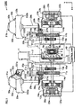
- the agitator 1000 of the present embodiment comprises: a drive motor 1 for supplying rotational driving forces; and two agitation vessels 30a and 30b.
- the drive motor 1 is connected to a differential block 3 by a driving shaft 2.
- Extended from the differential block 3 are two rotating shafts 10a and 10b, both of which are connected to rotation-direction switching blocks 11a and 11b, respectively.
- Each rotating shaft 10a/10b is provided in a manner to penetrate and protrude through the rotation-direction switching block 11a/11b, and a brake block 12a/12b is positioned at the other end of each rotating shaft 10a/10b.
- a rotating shaft 15a/15b extends through the rotation-direction switching block 11a/11b, and is connected to the agitation vessel 30a/30b via a rotating shaft 29a/29b and others.
- the agitator 1000 further comprises a control unit 40 for executing the drive control.
- the control unit 40 performs the drive control based on a drive program prestored in a memory (not shown) within the unit.
- the differential block 3 has a publicly-known structure similar to one used for a drive system of passenger automobiles and the like, and includes: a ring gear 5; a case 6; a pinion shaft 7; differential pinions 8a and 8b; side gears 9a and 9b.
- a drive pinion 4 is attached at the end and engages with the ring gear 5.
- One end of each rotating shaft 10a/10b is joined to the side gear 9a/9b.
- the differential block 3 transmits, to the two rotating shafts 10a and 10b, the driving force from the driving shaft 2 in a differential manner.
- the rotation-direction switching blocks 11a and 11b are respectively connected to the two rotating shafts 10a and 10b joined to the differential block 3, and each includes: large-diameter gear 14a/14b; gears 13a/13b and 16a/16b each having a smaller diameter than the large-diameter gear 14a/14b; and a small gear 17a/17b.
- a spool-shaped ring 18a/18b is attached in a manner that does not come in direct contact with the rotating shaft 15a/15b.
- Attached to each ring 18a/18b is a bifurcated lever 19a/19b connected to an electromagnetic solenoid 20a/20b via an operating shaft 21a/21b.
- each lever 19a/19b is capable of moving in the X direction in FIG. 1 due to the drive of the electromagnetic solenoid 20a/20b based on a control signal from the control unit 40. With this movement, the lever 19a/19b shifts the gear 16a/16b in the horizontal direction via the ring 18a/18b. Because of the shifting motion, in the rotation-direction switching block 11a/11b, the gear 16a/16b engages with either the gear 14a/14b or the gear 17a/17b.
- the brake blocks 12a and 12b are electromagnetic disc brakes, and each is positioned at the end of the rotating shaft 10a/10b extending from the differential block 3.
- the brake block 12a/12b includes: an electromagnetic coil 22a/22b; a spring 23a/23b; a disc 24a/24b; a pad 25a/25b; and a core 26a/26b.
- the brake blocks 12a and 12b alternately stop the rotation of the rotating shafts 10a and 10b based on an indication signal from the control unit 40.
- the agitator 1000 of the present embodiment includes two agitation vessels 30a and 30b, at the upper parts of which intake lids 31a and 31b are respectively mounted, and viscous (gel or sol) fluid 50 is retained in the substantially spherical containing spaces. Additionally, two discharge nozzles 32a/32b are formed on each agitator 30a/30b at the equator to face outward in the radial direction.
- the agitator 1000 has collection rings 33a and 33b that are positioned to surround the outer circumferences of the agitation vessels 30a and 30b, respectively.
- a receiving opening 331a is formed throughout the entire circumference, at a location corresponding to the discharge nozzles 32a/32b provided on the agitation vessel 30a/30b.
- the receiving opening 331a receives the viscous fluid 50 discharged from the discharge nozzles 32a/32b of each rotating agitation vessel 30a/30b.
- the collection rings 33a and 33b remain stationary and do not rotate with the agitation vessels 30a and 30b in a rotating motion.
- the collection rings 33a and 33b and the like are fixed onto stationary portions of the agitator 1000 by support frames although such frames are not shown in FIG. 1 and other figures.
- each collection ring 33a/33b At the lower portion, in the Z direction, of each collection ring 33a/33b, two discharge outlets 332a/332b are formed on the periphery.
- the viscous fluid 50 received from the receiving opening 331a is collected to the two discharge outlets 332a/332b by the collection ring 33a/33b functioning as a guide cover.
- collection containers are placed below the discharge outlets 332a/332b of the collection ring 33a/33b to receive the collected viscous fluid 50.
- a ball valve 322a is positioned in the discharge path.
- the ball valve 322a is closed to avoid spillage, while the ball valve 322a is opened when the viscous fluid 50 is collected.
- the collection ring 33a is, as described above, positioned to surround the outer circumference of the agitation vessel 30a, and part of the agitation vessel 30a is inserted into an aperture 333a of the collection ring 33a, created in the middle section. Additionally, the receiving opening 331a is formed to correspond to the discharge nozzles 32a when the agitation vessel 30a is inserted thereto.
- guide edges 334a and 335a are formed inside the collection ring 33a along the entire circumference.
- FIG. 2 shows only one of two agitation vessels 30a and 30b as well as one of two collection rings 33a and 33b provided in the agitator 1000-i.e. the agitation vessel 30a and the collection ring 33a shown on the left side of FIG. 1 , however, the other agitation vessel 30b and collection ring 33b also have the same structures as their counterparts, respectively.
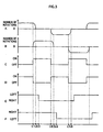
- individual sections (A to F) show the following: A) the rotation condition of the agitation vessel 30a; B) the rotation condition of the agitation vessel 30b; C) brake voltage applied to the brake block 12a; D) brake voltage applied to the brake block 12b; and E) and F) voltage for switching the rotation direction.
- the viscous fluid 50 is first fed into the agitation vessels 30a and 30b, and the intake lids 31a and 31b are closed. Then, prior to the drive motor 1 being driven, a control voltage is applied to the brake blocks 12a and 12b from the control unit 40 to thereby set the brake block 12a to an OFF state (the brake being released) and set the brake block 12b to an ON state (the brake being engaged). In this state of things, the rotational drive of the drive motor 1 is started by applying an operation-start signal to the drive motor 1 from the control unit 40.
- the rotating shaft 10b since the brake of the brake block 12b is engaged, the rotating shaft 10b does not rotate, while only the rotating shaft 10a starts its rotation. Then, the rotating shaft 29a is made to rotate via the gear 16a and rotating shaft 15a in the rotation-direction switching block 11a as well as via the gears 27a and 28a. As a result, the agitation vessel 30a, as shown on the left side of FIG. 1 , starts rotating at a predetermined number of rotations.
- the brake voltage from the control unit 40 is switched at timing t1, as shown in FIG. 3 . That is, the brake of the brake block 12a is engaged, while the brake of the brake block 12b being released. Subsequently, the agitation vessel 30a stops rotating at timing t2, as shown in the section A of FIG. 3 . On the other hand, as shown in the section B of FIG. 3 , the agitation vessel 30b starts its rotation at timing t1, and reaches a steady drive state at timing t2. As shown in the section E of FIG.
- a voltage is applied to the electromagnetic solenoid 20a from the control unit 40 at timing t3, and the gear 16a shifts rightward to engage with the gear 17a.
- the agitation vessel 30a is poised to invert its rotation.
- the brake voltage is switched at timing t4, and the brake is applied to the agitation vessel 30b.
- the rotation of the agitation vessel 30b subsequently stops at timing t5.
- the agitation vessel 30a starts rotating in the inverse direction, and then reaches the steady drive state at timing t5.
- the control unit 40 applies a voltage to the electromagnetic solenoid 20b at timing t6, and the gear 16b shifts leftward in FIG. 1 to engage with the gear 17b.
- the agitation vessel 30b is now poised to invert its rotation. From here onward, the rotation direction is switched at timings t7 and t8 in a similar fashion. Note that, as long as timing t3 is established between timings t2 and t4 and timing t6 is established between timings t5 and t7, the occurrences of timings t3 and t6 are not limited to the case shown in FIG. 3 .
- the viscous fluid 50 is held inside the agitation vessel 30a, as shown in FIG. 4A .
- This configuration is used when the agitator 1000 carries out the agitation operation.
- the intake lid 31a is also closed tight before the agitation operation to prevent the viscous fluid 50 from splashing out of the agitation vessel 30a.
- the discharge nozzles 32a are formed outwardly at the equator of the rotation operation being performed. It is designed to have the discharge nozzles 32a within the section where the largest portion of the viscous fluid 50 under centrifugal force is distributed, and therefore the viscous fluid 50 in the agitation vessel 30a is smoothly discharged in a reliable manner.
- the other agitation vessel 30b and the collection ring 33b attached thereto have the same operational and collection mechanisms as their counterparts, respectively.
- the agitator 1000 of the present embodiment therefore, it is less likely that the viscous fluid 50 remains inside the agitation vessels 30a and 30b after the collection, which allows to eliminate or reduce the need for cleaning for an operation following the current collection operation.
- the number of rotations (i.e. revolutions per minute) of the agitation vessels 30a and 30b for the collection of the viscous fluid 50 in the agitator 1000 is arbitrarily set according, for instance, to the viscosity of the viscous fluid 50 contained therein and the operating time that can be devoted for the collection, several dozen times per minute, for example, should suffice.
- the number of rotations of the agitation vessels 30a and 30b may be slightly increased correspondingly.
- the description of the drive method of the agitator 1000 in relation to the agitation is left out since the method is essentially the same as that of the agitator of Embodiment 1 above.
- the agitator 1000 is able to switch the rotation directions of the agitation vessels 30a and 30b between forward and reverse without changing the rotation direction of the drive motor 1 (the source of power) between forward and reverse.
- the drive motor 1 is started; 2) while the drive motor 1 is in the driving state, one of the brake blocks 12a and 12b is activated to thereby stop the rotation of one of the rotating shafts 10a and 10b extending from the differential block 3; 3) during this time, the rotation-direction switching block (11a or 11b) connected to the stopped rotating shaft (10a or 10b) is set in motion, and herewith the rotation direction of the rotating shaft (29a or 29b) is switched.
- the brake is applied to one rotating shaft (10a or 10b) to thereby keep the rotation in the stopped state, rotational driving forces are continuously transmitted to the other rotating shaft (10a or 10b) due to the function of the differential block 3, which is a differential unit.
- the agitator 1000 is able to alternately invert the rotation directions of the agitation vessels 30a and 30b while maintaining the rotation derived from the drive motor 1-i.e. the rotation of the driving shaft 2-steadily in a single direction.
- highly efficient agitation operation can be achieved.
- the agitator 1000 has advantageous effects in terms of a reduction in loads exerted on the drive motor 1 and shafts 2, 10a, 10b, 29a and 29b.
- an agitator 2000 according to Embodiment 2 is described with the aid of FIG. 5 .
- all the components of the agitator 2000 of the present embodiment are the same as those of Embodiment 1 above, except for guide cover portions accompanying the agitation vessels 30a and 30b, and thus a figure and a description regarding the structure of the agitator 2000 are left out here.
- the agitator 2000 of the present embodiment does not have the collection ring 33a surrounding the entire outer circumference of the agitation vessel 30a. Instead, collection containers 36a are positioned so as to correspond to the respective discharge nozzles 32a provided on the agitation vessel 30a, as shown in FIG. 5 . In addition, between each pair of the discharge nozzle 32a and the collection container 36a, a funnel-shaped collection assist device 34a is positioned to ensure guiding the discharged viscous fluid 50 into the collection container 36a.
- Each paired collection container 36a and collection assist device 34a are, individually, rotatably supported around an axis of rotation by a collection-container support frame 35a arranged in a standing manner on a disc-shaped collection-container base plate 37a.
- a vessel base plate 38a having a smaller diameter than the collection-container base plate 37a, is joined to the rotating shaft 29a which is joined to the agitation vessel 30a.
- the collection-container base plate 37a and vessel base plate 38a can be engaged with each other by inserting a lock pin 39a into a hole provided in each plate.
- the agitation vessel 30a, collection containers 36a and collection assist devices 34a rotate in synchronization with one another due to the rotation of the rotating shaft 29a.
- the holes in the collection-container base plate 37a and vessel base plate 38a for the insertion of the lock pin 39a are arranged so that the collection assist devices 34a are positioned at the outlets of the discharge nozzles 32a when the plates are engaged with each other.
- the vessel base plate 38a and collection-container base plate 37a are engaged with each other by the inserted lock pin 39a, and then the agitation vessel 30a, collection containers 36a and collection assist devices 34a are made to rotate in synchronization with one another by setting the rotating shaft 29a in rotation. Subsequently, the viscous fluid 50 is collected to the collection containers 36a due to centrifugal force of the rotation.
- the collection containers 36a and collection assist devices 34a each are designed to change their angles with the rotation of the rotating shaft 29a, as shown in FIG. 5 .
- the viscous fluid 50 discharged from the discharge nozzles 32a is collected to the collection containers 36a without splashing outside.
- the agitator 2000 also has another agitation vessel 30b, as in the case of the agitator 1000 according to Embodiment 1.
- the agitator 2000 of the present embodiment achieves the same advantageous effects as the agitator 1000 of Embodiment 1 above.
- the agitator 2000 of the present embodiment does not have the collection rings 33a and 33b surrounding the entire outer circumferences of the agitation vessels 30a and 30b.
- the collection assist devices 34a are provided at only positions corresponding to the respective discharge nozzles 32a. As a result, even if the collection assist devices 34a and the like need to be cleaned after every cycle of agitation and collection, it is possible to reduce the number of processes required for the cleaning.
- the number of discharge nozzles 32a and 32b are not confined to the case. Only one discharge nozzle, or alternatively three or more discharge nozzles may be provided for each agitation vessel, instead.
- the ball valves 322a are fitted in the discharge nozzles 32a and 32b, however, a structure other than this can be adopted if it allows to control retention and discharge of the viscous fluid 50.
- the following structure may be adopted: more than one aperture is created on the equator of the agitation vessel 30a; then, when the viscous fluid 50 is retained inside, such as during the agitation process, ring bodies are fit tightly around the outer circumferences of the agitation vessels 30a and 30b so as to block off each aperture.
- the multiple apertures can be opened at once by taking the ring bodies off, which reduces the number of processes required for the collection process.
- the agitators 1000 and 2000 of Embodiments 1 and 2 each have two agitation vessels 30a and 30b. However, an agitator having three or more agitation vessels is also within the scope of the present invention. Additionally, in Embodiments 1 and 2, the viscous fluid 50 is poured in each of the agitation vessels 30a and 30b to perform the agitation process, however, the agitation process may be carried out with one of the two agitation vessels empty (i.e. containing no viscous fluid 50).
- the above embodiments have the agitator vessels 30a and 30b having a spherical containing space; however, the containing space is not necessarily spherical.
- the containing space may be an elliptical sphere, or may have the shape of a solid of revolution with a rhombic or triangle cross section. Note that, when agitation vessels whose containing space has a shape other than spherical are adopted, the aperture of the discharge path should also be formed at the section where the largest portion of the viscous fluid 50 is distributed when the agitation vessels are rotating.
- the agitators 1000 and 2000 of Embodiments 1 and 2 above have a structure in which the center of the containing space of each agitation vessel 30a/30b lies on the axis of the rotating shaft 29a/29b; however, it is not always necessary to adopt this structure.
- the agitators 1000 and 2000 are used as examples of usage of containers for fluids; however, the present invention can also use other types of containers.
- the present invention may apply containers used for retaining food products, chemicals, cosmetics or the like therein.
- such containers include: ones for keeping viscous cosmetics, such as cosmetic creams and liquid foundations, and materials of these; and ones for preserving food products such as fermented soybean paste and ketchup.
- the dimple or a groove process may be applied to their internal surfaces. Note, however, that it is desirable not to inhibit the transfer of the fluid material to the discharge paths during the collection process.
- the outer shape of each agitation vessel 30a/30b and the shape of its internal, containing space are both spherical.
- the outer shape and the shape of the internal containing space are not limited to spherical.
- both the outer shape and the internal containing space may be cylindrical or conical.
- the internal containing space and the outside appearance do not necessarily have the same shape-e.g. the internal containing space is spherical while the outer shape is columnar or cubic.
- the drive motor 1 using electric power as a source of energy is given as an example of a source of power, however, other means that produces rotational drive-e.g. a petrol engine, a gas-turbine engine, a diesel engine-may be used, instead.
- the agitation target of the agitator of the present invention is not limited to the viscous fluid 50, which is used as an example in Embodiments 1 and 2 above, and any fluid material may be used for the target.
- any fluid material may be used for the target.
- the same effects can be achieved with not only liquid in a gel or sol state but also powder as well as a mixture of liquid and solid materials, for example.
Landscapes
- Chemical & Material Sciences (AREA)
- Chemical Kinetics & Catalysis (AREA)
- Engineering & Computer Science (AREA)
- Civil Engineering (AREA)
- Structural Engineering (AREA)
- Mixers Of The Rotary Stirring Type (AREA)
- Mixers With Rotating Receptacles And Mixers With Vibration Mechanisms (AREA)
- Accessories For Mixers (AREA)
- Packging For Living Organisms, Food Or Medicinal Products That Are Sensitive To Environmental Conditiond (AREA)
Claims (6)
- Rührwerk (1000), das ein Gefäß (30a, 30b), in dem sich ein Aufnahmeraum zum Aufnehmen eines Fluidmaterials (50) befindet, und eine Antriebsquelle (1) umfasst, die in Funktion auf das Gefäß Drehantriebskräfte, die um eine Achse (29a, 29b) herum erzeugt werden, so ausüben kann, dass das Fluidmaterial gerührt werden kann, wobei
das Gefäß einen Ausstoßweg (331a) aufweist, der außerhalb eines Abschnitts und in dessen Nähe innerhalb einer Innenfläche angeordnet ist, die den Aufnahmeraum umgibt, wobei der Abschnitt in einer radialen Drehrichtung am Weitesten von der Achse entfernt liegt, und
eine Antriebsquelle (1) übt mittels Drehantriebskräfte welche auf das Gefäß (30a, 30b) wirken eine Zentrifugalkraft auf das Fluidmaterial (50) aus, wobei die Zentrifugalkraft bewirkt, dass das Fluidmaterial zu dem Ausstoßweg strömt. - Rührwerk nach Anspruch 1, wobei eine Führungsabdeckung, mit der das durch die Drehantriebskräfte über den Ausstoßweg ausgestoßene Fluidmaterial aufgefangen wird, an einem Außenumfang des Gefäßes oder in dessen Nähe so angeordnet ist, dass es einem äußeren Ende des Ausstoßweges entspricht.
- Rührwerk nach Anspruch 2, das des Weiteren umfasst:einen Auffangbehälter, der sich in Funktion synchron zu dem Gefäß drehen und das über den Ausstoßweg ausgestoßene Fluidmaterial auffangen kann, wobei die Führungsabdeckung synchron sowohl zu dem Gefäß als auch dem Auffangbehälter gedreht werden kann.
- Rührwerk nach Anspruch 1, das des Weiteren umfasst:eine Ausgleichsgetriebeeinheit, die zwei Drehwellen aufweist, die sich von ihr aus erstrecken, und die in Funktion die Drehantriebskräfte aufnehmen kann und die aufgenommenen Drehantriebskräfte ausgleichend auf die Drehwellen übertragen kann;eine Bremseinheit, die in Funktion auf jede der Drehwellen einwirken kann und Drehung der Drehwellen abwechselnd unterbrechen kann;eine Drehrichtungs-Umschalteinheit, die mit wenigstens einer der Drehwellen gekoppelt ist und in Funktion Drehantriebskräfte von der gekoppelten Drehwelle ausgeben kann und dabei eine Drehrichtung der gekoppelten Drehwelle zwischen Vorwärts undRückwärts umschalten kann; undeine Steuereinheit, die in Funktion auf Basis einer vorgespeicherten Antriebssequenz Steuersignale einzeln an die Antriebsquelle, die Ausgleichsgetriebeeinheit, die Bremseinheit und die Drehrichtungs-Umschalteinheit ausgeben kann, wobei die Ausgleichsgetriebeeinheit und die Drehrichtungs-Umschalteinheit in einen Übertragungskanal der Drehantriebskräfte zwischen der Antriebsquelle und dem Gefäß eingefügt sind.
- Rührwerk nach Anspruch 1, wobei der Aufnahmeraum im Wesentlichen sphärisch ist und sich der Ausstoßweg von einem Äquator der Drehung und dessen Nähe an der den Aufnahmeraum umgebenden Innenfläche nach außen öffnet.
- Rührwerk nach Anspruch 1, wobei ein Ventilbetätigungsmechanismus, der in Funktion den Ausstoßweg frei öffnen und schließen kann, in dem Ausstoßweg angeordnet ist.
Applications Claiming Priority (1)
| Application Number | Priority Date | Filing Date | Title |
|---|---|---|---|
| JP2005291969A JP4883604B2 (ja) | 2005-10-05 | 2005-10-05 | 流動物容器および攪拌装置 |
Publications (2)
| Publication Number | Publication Date |
|---|---|
| EP1772185A1 EP1772185A1 (de) | 2007-04-11 |
| EP1772185B1 true EP1772185B1 (de) | 2010-12-15 |
Family
ID=37599331
Family Applications (1)
| Application Number | Title | Priority Date | Filing Date |
|---|---|---|---|
| EP06020729A Not-in-force EP1772185B1 (de) | 2005-10-05 | 2006-10-02 | Behälter für flüssige Stoff, wobei der Behälter als Rührbehälter ausgestattet ist |
Country Status (5)
| Country | Link |
|---|---|
| US (1) | US7476019B2 (de) |
| EP (1) | EP1772185B1 (de) |
| JP (1) | JP4883604B2 (de) |
| AT (1) | ATE491510T1 (de) |
| DE (1) | DE602006018841D1 (de) |
Families Citing this family (7)
| Publication number | Priority date | Publication date | Assignee | Title |
|---|---|---|---|---|
| US7988582B1 (en) * | 2004-10-14 | 2011-08-02 | Hydro-Gear Limited Partnership | Planet brake differential |
| JP4883604B2 (ja) * | 2005-10-05 | 2012-02-22 | 株式会社Bbcソフト | 流動物容器および攪拌装置 |
| JP4977891B2 (ja) * | 2007-06-18 | 2012-07-18 | 株式会社Bbcソフト | 攪拌装置 |
| CN109332036B (zh) * | 2018-10-09 | 2021-08-27 | 东莞为勤电子有限公司 | 一种自动湿式涂装机 |
| CN111331135B (zh) * | 2020-02-07 | 2022-06-21 | 江苏大学 | 一种用于激光选区熔化混合粉末的装置及方法 |
| DE102021121124A1 (de) * | 2021-08-13 | 2023-02-16 | Marco Systemanalyse Und Entwicklung Gmbh | Verfahren zum ausbringen von gemischten komponenten |
| CN118001978A (zh) * | 2024-04-07 | 2024-05-10 | 广东驱动力生物科技集团股份有限公司 | 一种饲料生产混合装置及其使用方法 |
Family Cites Families (47)
| Publication number | Priority date | Publication date | Assignee | Title |
|---|---|---|---|---|
| US592999A (en) * | 1897-11-02 | Churn | ||
| US266975A (en) * | 1882-11-07 | Washing-machine | ||
| US831A (en) * | 1838-07-09 | Churn for churning butter | ||
| US264213A (en) * | 1882-09-12 | Cylinder | ||
| US2353554A (en) * | 1944-07-11 | Endless track vehicle | ||
| US1498217A (en) * | 1924-06-17 | walker | ||
| US701370A (en) * | 1899-08-29 | 1902-06-03 | Henry Mosebach Jr | Ice-cream freezer. |
| US951055A (en) * | 1909-03-08 | 1910-03-01 | Prentice E Clark | Transmission-gearing. |
| US1205324A (en) * | 1913-07-25 | 1916-11-21 | Joseph E Camp | Combined washing-machine and wringer structure. |
| US1344366A (en) * | 1915-08-16 | 1920-06-22 | Holt Mfg Co | Double-gear transmission mechanism |
| US1253634A (en) * | 1915-12-08 | 1918-01-15 | Clarence A Schwanke | Operating mechanism for washing-machines. |
| US1611310A (en) * | 1925-11-02 | 1926-12-21 | Joseph L Grant | Clothes-washing attachment for vehicles |
| US1638965A (en) | 1926-03-06 | 1927-08-16 | Frederick G Sherbondy | Apparatus for bleaching wood pulp |
| US1665959A (en) * | 1927-12-12 | 1928-04-10 | George C Graham | Washing machine |
| FR704439A (fr) | 1930-10-28 | 1931-05-20 | Machine à mélanger et pétrir | |
| US1960815A (en) * | 1933-06-16 | 1934-05-29 | Thomas | Laundry machinery |
| US2165884A (en) * | 1937-03-06 | 1939-07-11 | Bendix Home Appliances Inc | Cleaning textile and similar materials |
| US2317117A (en) * | 1939-11-29 | 1943-04-20 | Anton C Schmelzer | Washing machine |
| US2349832A (en) * | 1941-10-20 | 1944-05-30 | Ohio Citizens Trust Company | Spectacular dust indicator for airway sanitary cleaning systems |
| US2392652A (en) * | 1943-06-16 | 1946-01-08 | Gen Motors Corp | Domestic appliance |
| US2508948A (en) * | 1946-01-22 | 1950-05-23 | Alfretta Hovermale | Washing machine |
| US2639794A (en) * | 1950-05-26 | 1953-05-26 | Gen Electric | Drive clutch for washing machines or the like |
| US2635726A (en) * | 1951-02-15 | 1953-04-21 | Gen Precision Lab Inc | Double reversing clutch |
| BE518679A (de) | 1952-03-25 | |||
| US2975563A (en) * | 1960-04-11 | 1961-03-21 | Bovensiepen Hans Friedrich | Driving arrangement for initiating and controlling rotary movements of two driven components together with and relative to each other |
| FR1390596A (fr) * | 1964-03-21 | 1965-02-26 | Machine à laver, en particulier avec décharge de travail commandée automatiquement | |
| GB1096905A (en) * | 1964-12-14 | 1967-12-29 | Hitachi Ltd | Washing machine |
| US3706443A (en) | 1970-08-19 | 1972-12-19 | Dynatech Corp | Agitation method and means |
| AT321844B (de) * | 1973-08-02 | 1975-04-25 | Binder Co Ag | Schwingwäscher |
| US4024935A (en) * | 1975-07-08 | 1977-05-24 | Kabushiki Kaisha Komatsu Seisakusho | Power transmission in double-drum winch |
| US4162129A (en) * | 1977-08-29 | 1979-07-24 | Wine Breather, Inc. | Wine aerator |
| US4283928A (en) * | 1979-08-24 | 1981-08-18 | General Electric Company | Transmission for washing machine |
| US5205141A (en) * | 1990-12-28 | 1993-04-27 | Whirlpool Corporation | Reciprocating laundry basket for an automatic washer |
| JPH0557163A (ja) * | 1991-08-30 | 1993-03-09 | Maikuronikusu Kk | 偏心回転混合・洗浄装置 |
| JP2672240B2 (ja) | 1992-12-10 | 1997-11-05 | 不二精機株式会社 | 飯等の食材の混合装置 |
| JPH08192034A (ja) * | 1995-01-17 | 1996-07-30 | Mitsubishi Heavy Ind Ltd | 液体への気体溶解装置 |
| JPH10343A (ja) | 1996-06-18 | 1998-01-06 | Kazu Shiotani | 砂漠の砂にピート・モス等の比重の違う粉粒体物質 を簡単に、まんべんなく混ぜ合わせる方法、および、 その方法を可能とする球体混合器 |
| US6854300B2 (en) * | 1998-05-12 | 2005-02-15 | Dyson Limited | Method and apparatus for containing and agitating the contents of a container |
| JP2001017950A (ja) * | 1999-07-06 | 2001-01-23 | Koji Kaneda | 生分解性廃棄物処理装置 |
| US6332980B1 (en) * | 2000-03-13 | 2001-12-25 | Jack Moorehead | System for separating algae and other contaminants from a water stream |
| JP2001286745A (ja) | 2000-04-05 | 2001-10-16 | Fuji Photo Film Co Ltd | 液体又は溶液の混合方法及び装置 |
| NZ505748A (en) * | 2000-07-13 | 2002-08-28 | Fisher & Paykel Appliances Ltd | Perforation(s) of laundry machine drum with aperture area greater when viewed along drum surface than when viewed perpendicular to surface |
| US6342021B1 (en) * | 2000-12-08 | 2002-01-29 | Torvec, Inc. | Steer-drive for vehicles |
| JP3845837B2 (ja) * | 2001-04-09 | 2006-11-15 | 株式会社ジャパン・エンジニアリング・サプライ | 生ゴミ処理機 |
| WO2003087459A1 (en) * | 2002-04-10 | 2003-10-23 | Fisher & Paykel Appliances Limited | A laundry appliance |
| JP4276008B2 (ja) * | 2003-07-14 | 2009-06-10 | 株式会社ビービーシー・ソフト | 攪拌装置 |
| JP4883604B2 (ja) * | 2005-10-05 | 2012-02-22 | 株式会社Bbcソフト | 流動物容器および攪拌装置 |
-
2005
- 2005-10-05 JP JP2005291969A patent/JP4883604B2/ja not_active Expired - Fee Related
- 2005-11-25 US US11/286,952 patent/US7476019B2/en not_active Expired - Fee Related
-
2006
- 2006-10-02 EP EP06020729A patent/EP1772185B1/de not_active Not-in-force
- 2006-10-02 DE DE602006018841T patent/DE602006018841D1/de active Active
- 2006-10-02 AT AT06020729T patent/ATE491510T1/de not_active IP Right Cessation
Also Published As
| Publication number | Publication date |
|---|---|
| US20070076520A1 (en) | 2007-04-05 |
| HK1104983A1 (en) | 2008-02-01 |
| JP4883604B2 (ja) | 2012-02-22 |
| JP2007098292A (ja) | 2007-04-19 |
| US7476019B2 (en) | 2009-01-13 |
| EP1772185A1 (de) | 2007-04-11 |
| DE602006018841D1 (de) | 2011-01-27 |
| ATE491510T1 (de) | 2011-01-15 |
Similar Documents
| Publication | Publication Date | Title |
|---|---|---|
| EP1772185B1 (de) | Behälter für flüssige Stoff, wobei der Behälter als Rührbehälter ausgestattet ist | |
| CN201015731Y (zh) | 湿法制粒机 | |
| KR101106919B1 (ko) | 믹서기 | |
| JP2009220035A (ja) | プラネタリミキサ | |
| CN202096792U (zh) | 搅拌脱泡装置所使用的容器及搅拌脱泡装置 | |
| HK1104983B (en) | Vessel for containing fluid material and agitator having the vessel as agitation vessel | |
| JP2000084388A (ja) | 攪拌装置および攪拌方法 | |
| JP2012136284A (ja) | プランジャ挿入装置、及び、プランジャ挿入装置用のアダプタ、並びに、シリンジユニットの製造方法 | |
| CN209885742U (zh) | 一种搅拌装置 | |
| KR20110058794A (ko) | 재료 충전 장치 및 재료 충전 방법 | |
| CN219849267U (zh) | 一种opo微胶囊生产溶解用磁力搅拌装置 | |
| CN209158634U (zh) | 用于余泥处理的混炼机 | |
| KR20030071438A (ko) | 음식물 쓰레기 처리용 교반기 | |
| CN212017617U (zh) | 一种倾斜式圆筒混料机 | |
| CN108818996A (zh) | 一种塑胶生产用原材料搅拌混合机 | |
| JP2552878B2 (ja) | 遊星運動混合機 | |
| CN220026764U (zh) | 一种可调角度的锥形混合机 | |
| KR200458001Y1 (ko) | 자동 혼합 화장품 용기 | |
| CN219187911U (zh) | 一种清洗装置 | |
| JP2016195991A (ja) | 三次元式の自転・公転式の撹拌装置 | |
| CN206285803U (zh) | 香精搅拌装置 | |
| CN223351685U (zh) | 一种化学药品制剂加工用反应釜 | |
| JP3866789B2 (ja) | 回転式コンテナ混合装置 | |
| CN223530359U (zh) | 一种饮料混合装置 | |
| CN216449271U (zh) | 加样装置 |
Legal Events
| Date | Code | Title | Description |
|---|---|---|---|
| PUAI | Public reference made under article 153(3) epc to a published international application that has entered the european phase |
Free format text: ORIGINAL CODE: 0009012 |
|
| AK | Designated contracting states |
Kind code of ref document: A1 Designated state(s): AT BE BG CH CY CZ DE DK EE ES FI FR GB GR HU IE IS IT LI LT LU LV MC NL PL PT RO SE SI SK TR |
|
| AX | Request for extension of the european patent |
Extension state: AL BA HR MK YU |
|
| 17P | Request for examination filed |
Effective date: 20070911 |
|
| AKX | Designation fees paid |
Designated state(s): AT BE BG CH CY CZ DE DK EE ES FI FR GB GR HU IE IS IT LI LT LU LV MC NL PL PT RO SE SI SK TR |
|
| REG | Reference to a national code |
Ref country code: HK Ref legal event code: DE Ref document number: 1104983 Country of ref document: HK |
|
| GRAP | Despatch of communication of intention to grant a patent |
Free format text: ORIGINAL CODE: EPIDOSNIGR1 |
|
| GRAS | Grant fee paid |
Free format text: ORIGINAL CODE: EPIDOSNIGR3 |
|
| GRAA | (expected) grant |
Free format text: ORIGINAL CODE: 0009210 |
|
| AK | Designated contracting states |
Kind code of ref document: B1 Designated state(s): AT BE BG CH CY CZ DE DK EE ES FI FR GB GR HU IE IS IT LI LT LU LV MC NL PL PT RO SE SI SK TR |
|
| REG | Reference to a national code |
Ref country code: CH Ref legal event code: EP Ref country code: GB Ref legal event code: FG4D |
|
| REG | Reference to a national code |
Ref country code: IE Ref legal event code: FG4D |
|
| REF | Corresponds to: |
Ref document number: 602006018841 Country of ref document: DE Date of ref document: 20110127 Kind code of ref document: P |
|
| REG | Reference to a national code |
Ref country code: NL Ref legal event code: VDEP Effective date: 20101215 |
|
| REG | Reference to a national code |
Ref country code: HK Ref legal event code: GR Ref document number: 1104983 Country of ref document: HK |
|
| PG25 | Lapsed in a contracting state [announced via postgrant information from national office to epo] |
Ref country code: LT Free format text: LAPSE BECAUSE OF FAILURE TO SUBMIT A TRANSLATION OF THE DESCRIPTION OR TO PAY THE FEE WITHIN THE PRESCRIBED TIME-LIMIT Effective date: 20101215 |
|
| LTIE | Lt: invalidation of european patent or patent extension |
Effective date: 20101215 |
|
| PG25 | Lapsed in a contracting state [announced via postgrant information from national office to epo] |
Ref country code: SI Free format text: LAPSE BECAUSE OF FAILURE TO SUBMIT A TRANSLATION OF THE DESCRIPTION OR TO PAY THE FEE WITHIN THE PRESCRIBED TIME-LIMIT Effective date: 20101215 Ref country code: BG Free format text: LAPSE BECAUSE OF FAILURE TO SUBMIT A TRANSLATION OF THE DESCRIPTION OR TO PAY THE FEE WITHIN THE PRESCRIBED TIME-LIMIT Effective date: 20110315 Ref country code: CY Free format text: LAPSE BECAUSE OF FAILURE TO SUBMIT A TRANSLATION OF THE DESCRIPTION OR TO PAY THE FEE WITHIN THE PRESCRIBED TIME-LIMIT Effective date: 20101215 Ref country code: AT Free format text: LAPSE BECAUSE OF FAILURE TO SUBMIT A TRANSLATION OF THE DESCRIPTION OR TO PAY THE FEE WITHIN THE PRESCRIBED TIME-LIMIT Effective date: 20101215 Ref country code: FI Free format text: LAPSE BECAUSE OF FAILURE TO SUBMIT A TRANSLATION OF THE DESCRIPTION OR TO PAY THE FEE WITHIN THE PRESCRIBED TIME-LIMIT Effective date: 20101215 Ref country code: SE Free format text: LAPSE BECAUSE OF FAILURE TO SUBMIT A TRANSLATION OF THE DESCRIPTION OR TO PAY THE FEE WITHIN THE PRESCRIBED TIME-LIMIT Effective date: 20101215 Ref country code: LV Free format text: LAPSE BECAUSE OF FAILURE TO SUBMIT A TRANSLATION OF THE DESCRIPTION OR TO PAY THE FEE WITHIN THE PRESCRIBED TIME-LIMIT Effective date: 20101215 Ref country code: NL Free format text: LAPSE BECAUSE OF FAILURE TO SUBMIT A TRANSLATION OF THE DESCRIPTION OR TO PAY THE FEE WITHIN THE PRESCRIBED TIME-LIMIT Effective date: 20101215 |
|
| PG25 | Lapsed in a contracting state [announced via postgrant information from national office to epo] |
Ref country code: EE Free format text: LAPSE BECAUSE OF FAILURE TO SUBMIT A TRANSLATION OF THE DESCRIPTION OR TO PAY THE FEE WITHIN THE PRESCRIBED TIME-LIMIT Effective date: 20101215 Ref country code: BE Free format text: LAPSE BECAUSE OF FAILURE TO SUBMIT A TRANSLATION OF THE DESCRIPTION OR TO PAY THE FEE WITHIN THE PRESCRIBED TIME-LIMIT Effective date: 20101215 Ref country code: CZ Free format text: LAPSE BECAUSE OF FAILURE TO SUBMIT A TRANSLATION OF THE DESCRIPTION OR TO PAY THE FEE WITHIN THE PRESCRIBED TIME-LIMIT Effective date: 20101215 Ref country code: ES Free format text: LAPSE BECAUSE OF FAILURE TO SUBMIT A TRANSLATION OF THE DESCRIPTION OR TO PAY THE FEE WITHIN THE PRESCRIBED TIME-LIMIT Effective date: 20110326 Ref country code: PT Free format text: LAPSE BECAUSE OF FAILURE TO SUBMIT A TRANSLATION OF THE DESCRIPTION OR TO PAY THE FEE WITHIN THE PRESCRIBED TIME-LIMIT Effective date: 20110415 Ref country code: GR Free format text: LAPSE BECAUSE OF FAILURE TO SUBMIT A TRANSLATION OF THE DESCRIPTION OR TO PAY THE FEE WITHIN THE PRESCRIBED TIME-LIMIT Effective date: 20110316 Ref country code: IS Free format text: LAPSE BECAUSE OF FAILURE TO SUBMIT A TRANSLATION OF THE DESCRIPTION OR TO PAY THE FEE WITHIN THE PRESCRIBED TIME-LIMIT Effective date: 20110415 |
|
| PG25 | Lapsed in a contracting state [announced via postgrant information from national office to epo] |
Ref country code: SK Free format text: LAPSE BECAUSE OF FAILURE TO SUBMIT A TRANSLATION OF THE DESCRIPTION OR TO PAY THE FEE WITHIN THE PRESCRIBED TIME-LIMIT Effective date: 20101215 Ref country code: PL Free format text: LAPSE BECAUSE OF FAILURE TO SUBMIT A TRANSLATION OF THE DESCRIPTION OR TO PAY THE FEE WITHIN THE PRESCRIBED TIME-LIMIT Effective date: 20101215 Ref country code: RO Free format text: LAPSE BECAUSE OF FAILURE TO SUBMIT A TRANSLATION OF THE DESCRIPTION OR TO PAY THE FEE WITHIN THE PRESCRIBED TIME-LIMIT Effective date: 20101215 |
|
| PLBE | No opposition filed within time limit |
Free format text: ORIGINAL CODE: 0009261 |
|
| STAA | Information on the status of an ep patent application or granted ep patent |
Free format text: STATUS: NO OPPOSITION FILED WITHIN TIME LIMIT |
|
| PG25 | Lapsed in a contracting state [announced via postgrant information from national office to epo] |
Ref country code: DK Free format text: LAPSE BECAUSE OF FAILURE TO SUBMIT A TRANSLATION OF THE DESCRIPTION OR TO PAY THE FEE WITHIN THE PRESCRIBED TIME-LIMIT Effective date: 20101215 |
|
| 26N | No opposition filed |
Effective date: 20110916 |
|
| PG25 | Lapsed in a contracting state [announced via postgrant information from national office to epo] |
Ref country code: IT Free format text: LAPSE BECAUSE OF FAILURE TO SUBMIT A TRANSLATION OF THE DESCRIPTION OR TO PAY THE FEE WITHIN THE PRESCRIBED TIME-LIMIT Effective date: 20101215 |
|
| REG | Reference to a national code |
Ref country code: DE Ref legal event code: R097 Ref document number: 602006018841 Country of ref document: DE Effective date: 20110916 |
|
| PG25 | Lapsed in a contracting state [announced via postgrant information from national office to epo] |
Ref country code: MC Free format text: LAPSE BECAUSE OF NON-PAYMENT OF DUE FEES Effective date: 20111031 |
|
| REG | Reference to a national code |
Ref country code: CH Ref legal event code: PL |
|
| PG25 | Lapsed in a contracting state [announced via postgrant information from national office to epo] |
Ref country code: CH Free format text: LAPSE BECAUSE OF NON-PAYMENT OF DUE FEES Effective date: 20111031 Ref country code: LI Free format text: LAPSE BECAUSE OF NON-PAYMENT OF DUE FEES Effective date: 20111031 |
|
| REG | Reference to a national code |
Ref country code: IE Ref legal event code: MM4A |
|
| PG25 | Lapsed in a contracting state [announced via postgrant information from national office to epo] |
Ref country code: IE Free format text: LAPSE BECAUSE OF NON-PAYMENT OF DUE FEES Effective date: 20111002 |
|
| PG25 | Lapsed in a contracting state [announced via postgrant information from national office to epo] |
Ref country code: LU Free format text: LAPSE BECAUSE OF NON-PAYMENT OF DUE FEES Effective date: 20111002 |
|
| PG25 | Lapsed in a contracting state [announced via postgrant information from national office to epo] |
Ref country code: TR Free format text: LAPSE BECAUSE OF FAILURE TO SUBMIT A TRANSLATION OF THE DESCRIPTION OR TO PAY THE FEE WITHIN THE PRESCRIBED TIME-LIMIT Effective date: 20101215 |
|
| PG25 | Lapsed in a contracting state [announced via postgrant information from national office to epo] |
Ref country code: HU Free format text: LAPSE BECAUSE OF FAILURE TO SUBMIT A TRANSLATION OF THE DESCRIPTION OR TO PAY THE FEE WITHIN THE PRESCRIBED TIME-LIMIT Effective date: 20101215 |
|
| REG | Reference to a national code |
Ref country code: FR Ref legal event code: PLFP Year of fee payment: 10 |
|
| PGFP | Annual fee paid to national office [announced via postgrant information from national office to epo] |
Ref country code: GB Payment date: 20151022 Year of fee payment: 10 Ref country code: DE Payment date: 20151027 Year of fee payment: 10 |
|
| PGFP | Annual fee paid to national office [announced via postgrant information from national office to epo] |
Ref country code: FR Payment date: 20151022 Year of fee payment: 10 |
|
| REG | Reference to a national code |
Ref country code: DE Ref legal event code: R119 Ref document number: 602006018841 Country of ref document: DE |
|
| GBPC | Gb: european patent ceased through non-payment of renewal fee |
Effective date: 20161002 |
|
| REG | Reference to a national code |
Ref country code: FR Ref legal event code: ST Effective date: 20170630 |
|
| PG25 | Lapsed in a contracting state [announced via postgrant information from national office to epo] |
Ref country code: FR Free format text: LAPSE BECAUSE OF NON-PAYMENT OF DUE FEES Effective date: 20161102 Ref country code: DE Free format text: LAPSE BECAUSE OF NON-PAYMENT OF DUE FEES Effective date: 20170503 Ref country code: GB Free format text: LAPSE BECAUSE OF NON-PAYMENT OF DUE FEES Effective date: 20161002 |