EP1772896A2 - Lampe - Google Patents
Lampe Download PDFInfo
- Publication number
- EP1772896A2 EP1772896A2 EP06121828A EP06121828A EP1772896A2 EP 1772896 A2 EP1772896 A2 EP 1772896A2 EP 06121828 A EP06121828 A EP 06121828A EP 06121828 A EP06121828 A EP 06121828A EP 1772896 A2 EP1772896 A2 EP 1772896A2
- Authority
- EP
- European Patent Office
- Prior art keywords
- electrically conductive
- power supply
- supply section
- lamp
- potting compound
- Prior art date
- Legal status (The legal status is an assumption and is not a legal conclusion. Google has not performed a legal analysis and makes no representation as to the accuracy of the status listed.)
- Granted
Links
- 150000001875 compounds Chemical class 0.000 claims abstract description 55
- 239000000853 adhesive Substances 0.000 claims abstract description 40
- 230000001070 adhesive effect Effects 0.000 claims abstract description 40
- 238000004382 potting Methods 0.000 claims description 54
- 229910000679 solder Inorganic materials 0.000 claims description 36
- 238000010438 heat treatment Methods 0.000 claims description 7
- 230000005672 electromagnetic field Effects 0.000 claims description 3
- 230000001939 inductive effect Effects 0.000 claims description 2
- 238000007789 sealing Methods 0.000 abstract 1
- 239000004033 plastic Substances 0.000 description 13
- 229910052751 metal Inorganic materials 0.000 description 11
- 239000002184 metal Substances 0.000 description 11
- ZOKXTWBITQBERF-UHFFFAOYSA-N Molybdenum Chemical compound [Mo] ZOKXTWBITQBERF-UHFFFAOYSA-N 0.000 description 3
- 239000000463 material Substances 0.000 description 3
- 229910052750 molybdenum Inorganic materials 0.000 description 3
- 239000011733 molybdenum Substances 0.000 description 3
- PXHVJJICTQNCMI-UHFFFAOYSA-N Nickel Chemical compound [Ni] PXHVJJICTQNCMI-UHFFFAOYSA-N 0.000 description 2
- 239000004642 Polyimide Substances 0.000 description 2
- BQCADISMDOOEFD-UHFFFAOYSA-N Silver Chemical compound [Ag] BQCADISMDOOEFD-UHFFFAOYSA-N 0.000 description 2
- 239000011888 foil Substances 0.000 description 2
- 229910052736 halogen Inorganic materials 0.000 description 2
- 150000002367 halogens Chemical class 0.000 description 2
- 238000000034 method Methods 0.000 description 2
- 229920001721 polyimide Polymers 0.000 description 2
- 229910052709 silver Inorganic materials 0.000 description 2
- 239000004332 silver Substances 0.000 description 2
- VYZAMTAEIAYCRO-UHFFFAOYSA-N Chromium Chemical compound [Cr] VYZAMTAEIAYCRO-UHFFFAOYSA-N 0.000 description 1
- RYGMFSIKBFXOCR-UHFFFAOYSA-N Copper Chemical compound [Cu] RYGMFSIKBFXOCR-UHFFFAOYSA-N 0.000 description 1
- 239000004593 Epoxy Substances 0.000 description 1
- 239000004696 Poly ether ether ketone Substances 0.000 description 1
- VYPSYNLAJGMNEJ-UHFFFAOYSA-N Silicium dioxide Chemical compound O=[Si]=O VYPSYNLAJGMNEJ-UHFFFAOYSA-N 0.000 description 1
- JUPQTSLXMOCDHR-UHFFFAOYSA-N benzene-1,4-diol;bis(4-fluorophenyl)methanone Chemical compound OC1=CC=C(O)C=C1.C1=CC(F)=CC=C1C(=O)C1=CC=C(F)C=C1 JUPQTSLXMOCDHR-UHFFFAOYSA-N 0.000 description 1
- 239000000919 ceramic Substances 0.000 description 1
- 229910052802 copper Inorganic materials 0.000 description 1
- 239000010949 copper Substances 0.000 description 1
- 230000001419 dependent effect Effects 0.000 description 1
- 239000003822 epoxy resin Substances 0.000 description 1
- 239000011521 glass Substances 0.000 description 1
- PCHJSUWPFVWCPO-UHFFFAOYSA-N gold Chemical compound [Au] PCHJSUWPFVWCPO-UHFFFAOYSA-N 0.000 description 1
- 229910052737 gold Inorganic materials 0.000 description 1
- 239000010931 gold Substances 0.000 description 1
- LNEPOXFFQSENCJ-UHFFFAOYSA-N haloperidol Chemical compound C1CC(O)(C=2C=CC(Cl)=CC=2)CCN1CCCC(=O)C1=CC=C(F)C=C1 LNEPOXFFQSENCJ-UHFFFAOYSA-N 0.000 description 1
- 230000017525 heat dissipation Effects 0.000 description 1
- 238000002347 injection Methods 0.000 description 1
- 239000007924 injection Substances 0.000 description 1
- 239000007788 liquid Substances 0.000 description 1
- 230000008018 melting Effects 0.000 description 1
- 238000002844 melting Methods 0.000 description 1
- 239000002905 metal composite material Substances 0.000 description 1
- 229910052759 nickel Inorganic materials 0.000 description 1
- 229920000647 polyepoxide Polymers 0.000 description 1
- 229920002530 polyetherether ketone Polymers 0.000 description 1
- 229920001296 polysiloxane Polymers 0.000 description 1
- 238000002360 preparation method Methods 0.000 description 1
- 238000007711 solidification Methods 0.000 description 1
- 230000008023 solidification Effects 0.000 description 1
- 229920001169 thermoplastic Polymers 0.000 description 1
- 239000004416 thermosoftening plastic Substances 0.000 description 1
- 239000005341 toughened glass Substances 0.000 description 1
- 238000009281 ultraviolet germicidal irradiation Methods 0.000 description 1
- 238000003466 welding Methods 0.000 description 1
Images
Classifications
-
- H—ELECTRICITY
- H01—ELECTRIC ELEMENTS
- H01J—ELECTRIC DISCHARGE TUBES OR DISCHARGE LAMPS
- H01J9/00—Apparatus or processes specially adapted for the manufacture, installation, removal, maintenance of electric discharge tubes, discharge lamps, or parts thereof; Recovery of material from discharge tubes or lamps
- H01J9/38—Exhausting, degassing, filling, or cleaning vessels
-
- H—ELECTRICITY
- H01—ELECTRIC ELEMENTS
- H01J—ELECTRIC DISCHARGE TUBES OR DISCHARGE LAMPS
- H01J5/00—Details relating to vessels or to leading-in conductors common to two or more basic types of discharge tubes or lamps
- H01J5/50—Means forming part of the tube or lamps for the purpose of providing electrical connection to it
- H01J5/54—Means forming part of the tube or lamps for the purpose of providing electrical connection to it supported by a separate part, e.g. base
- H01J5/62—Connection of wires protruding from the vessel to connectors carried by the separate part
-
- H—ELECTRICITY
- H01—ELECTRIC ELEMENTS
- H01K—ELECTRIC INCANDESCENT LAMPS
- H01K1/00—Details
- H01K1/42—Means forming part of the lamp for the purpose of providing electrical connection, or support for, the lamp
- H01K1/46—Means forming part of the lamp for the purpose of providing electrical connection, or support for, the lamp supported by a separate part, e.g. base, cap
Definitions
- the invention relates to a lamp according to the preamble of patent claim 1.
- Such lamps are for example from the EP-A 1 006 551 known.
- This publication discloses a halogen incandescent lamp for a motor vehicle headlamp with an enclosed by a glass lamp vessel incandescent and two power supply wires for the filament, which protrude from the sealed end of the lamp vessel.
- the sealed end of the lamp vessel is fixed in a lamp base provided with two electrical terminals for the lamp.
- the power supply wires are each connected to one of the electrical terminals of the lamp by welding.
- the lamp according to the invention comprises at least one lamp enclosed by a lamp vessel and at least one first power supply section for supplying energy to the at least one lamp and a lamp base, which is equipped with at least one second power supply section for supplying power to the at least one lamp, wherein an electrically conductive potting compound or an electrically conductive adhesive or an electrically conductive solder is provided, by means of which or an electrically conductive connection between the at least one first power supply section and the at least one second power supply section is produced.
- the lamp base of the lamp according to the invention preferably has at least one container into which the at least one first power supply section and the at least one second power supply section project, wherein the container is at least as far filled with the electrically conductive potting compound or the electrically conductive adhesive or the electrically conductive solder in that the at least one first power supply section and the at least one second power supply section are wetted by the electrically conductive potting compound or the electrically conductive adhesive or the electrically conductive solder.
- the at least one container a defined space within the lamp cap is provided with a predetermined volume for the electrically conductive potting compound or the electrically conductive adhesive or the electrically conductive solder.
- the at least one container To produce the electrical contact between the at least one first power supply section and the at least one second power supply section, it is sufficient for the at least one container to be so far connected to the electrically conductive potting compound or the electrically conductive potting compound To fill adhesive or the electrically conductive solder that the at least one first power supply section and the at least one second power supply section of the electrically conductive potting compound or the electrically conductive adhesive or the electrically conductive solder are wetted.
- the electrical contact between the at least one first power supply section and the at least one second power supply section is thereby directly via the electrically conductive potting compound or the electrically conductive adhesive or the electrically conductive solder and / or, if the at least one container has metallic walls over the made of metallic walls.
- the at least one first power supply section and the at least one second power supply section are arranged without contact with each other in order to provide sufficient clearance for the at least one first power supply section during the above-mentioned adjustment of the at least one light source.
- the distance between the first and second current supply sections is as small as possible.
- the surfaces of the first and / or second power supply sections may be partially or completely coated with a high-conductivity metal.
- the first and / or second power supply sections may be partially silver plated, gold plated, copper plated, chrome plated or nickel plated.
- the at least one first power supply section may have a cup-like end into which projects the at least one second power supply section and with the electrically conductive potting compound or electrically conductive adhesive or the electrically conductive solder is at least partially filled.
- the at least one second power supply section may have a cup-like end into which the at least one first power supply section protrudes and which is at least partially filled with the electrically conductive potting compound or the electrically conductive adhesive or the electrically conductive solder.
- the at least one first power supply section may have a hole or a cut into which the at least one second power supply section protrudes and which is at least partially covered with the electrically conductive potting compound or the electrically conductive adhesive or the electrically conductive solder, to keep the current density in the electrically conductive potting compound or the electrically conductive adhesive or the electrically conductive solder low.
- the at least one second power supply section may have a hole or a cutout into which the at least one first power supply section protrudes, and that with the electrically conductive potting compound or the electrically conductive adhesive or the electrically conductive solder is at least partially covered.
- the at least one first power supply section and the at least one second power supply section do not necessarily have to be arranged without contact. In order to keep the contact resistance between them as small as possible, they can also touch.
- the first or second current supply section projecting into the cup-like end or into the hole or the cutout can touch the cup wall or the edge of the hole or the cutout.
- the lamp base in the region of the at least one container is equipped with means which enable inductive heating of the electrically conductive potting compound arranged in the container or the electrically conductive adhesive or the electrically conductive solder by means of electromagnetic fields.
- the encapsulated in the lamp base electrically conductive potting compound or the electrically conductive adhesive or the electrically conductive solder can be heated without contact to cure the electrically conductive potting compound or the electrically conductive adhesive or to melt the electrically conductive solder.
- the side walls of the aforementioned container are formed by a metal sleeve.
- an electrical current can be induced in the side walls around the electrically conductive potting compound or the electrically conductive adhesive arranged in the container or electrically to heat conductive solder inductively.
- the side walls of the container may be made of plastic and formed integrally with a plastic base part.
- a metal ring may be embedded in the side walls in order to inductively heat the electrically conductive potting compound arranged in the container or the electrically conductive adhesive or the electrically conductive solder.
- On the metal ring can also be dispensed with, since due to their electrical conductivity in the electrically conductive potting compound or the electrically conductive adhesive or the electrically conductive solder itself a current for heating the potting compound or the adhesive or the solder can be induced.
- connection between the at least one first power supply section and the at least one second power supply section and the electrically conductive potting compound or the electrically conductive adhesive or the electrically conductive solder is gas-tight to prevent the ingress of moisture into the lamp cap.
- the second power supply portions of the lamp base have projecting ends formed as electrical terminals of the lamp.
- the at least one first power supply section is preferably a power supply section protruding from the lamp vessel, in particular a power supply wire protruding from the lamp vessel.
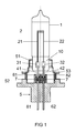
- first embodiment of the invention is a halogen incandescent lamp, which is intended for use as a light source in a motor vehicle headlight.
- This lamp has a lamp envelope 1 made of quartz glass, which is sealed at one end by means of a Quetschfußes 10.
- an incandescent filament 2 is arranged, the filament outlets 21, 22 in each case via a molybdenum foil 31 or 32 embedded in a gas-tight manner in the presser foot 10 with a protruding from the presser foot 10, molybdenum existing power supply wire 41 and 42 are connected.
- the presser foot 10 of the lamp vessel 1 is fixed in a metallic holder part 51 of the lamp cap 5.
- the metallic holder part 51 is anchored in a plastic part 52 of the lamp cap 5. From the plastic base part 52 protrude two metallic contact lugs 61, 62, which are formed as stamped sheet metal parts and are each electrically connected to one of the power supply wires 41 and 42, respectively.
- the electrically conductive connection between the first power supply wire 41 and the first metallic contact lug 61 is produced by means of an electrically conductive potting compound 7, which is arranged in a first hollow cylindrical container 81.
- the first metallic contact lug 61 protrudes through the bottom into the interior of the first container 81, while the first power supply wire 41 protrudes from above into the interior of the first container 81, so that the first power supply wire 41 and the first contact lug 61 at a distance of approx.
- the electrically conductive potting compound 7 wets both the first contact lug 61 and the first power supply wire 41 and fills the gap between the first power supply wire 41 and the first contact lug 61.
- the electrically conductive connection between the second power supply wire 42 and the second metal contact lug 62 is made by means of an electrically conductive potting compound 7, which is arranged in a second hollow cylindrical container 82.
- the second metallic contact lug 62 projects through the bottom into the interior of the second Container 82, while the second power supply wire 42 protrudes from above into the interior of the second container 82, so that the second power supply wire 42 and the second contact lug 62 are arranged at a distance of about 1 millimeter in the second container 82.
- the electrically conductive potting compound 7 wets both the second contact lug 62 and the second power supply wire 42 and fills the gap between the second power supply wire 42 and the second contact lug 62.
- the walls of the two containers 81, 82 for the potting compound 7 are integrally formed with the plastic base part 52, for example as a plastic injection molded part.
- the potting compounds 7 in the containers 81, 82 are arranged electrically isolated from each other.
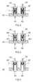
- FIG. 2 shows a cross section through the plastic base part 52 in the region of the connection between the power supply wires 41, 42 and the metallic contact lugs 61, 62 according to the second embodiment of the invention.
- This second embodiment differs from the first embodiment of the invention described above only in that the side walls of the two containers for the potting compound 7 are each formed by a metal tube 81 'and 82', one end of which is injected into the plastic base part 52.
- the first and second embodiments are the same.
- FIG. 3 shows a cross section through the plastic base part 52 in the region of the connection between the power supply wires 41, 42 and the metallic contact lugs 61, 62 according to the third embodiment of the invention.
- This third embodiment differs from the second embodiment only in that the contact lugs 61, 62 each have a cup-like end 611, 621, into which the power supply wires 41, 42 protrude.
- the cup-like ends 611, 621 are filled with potting compound 7.
- FIG. 4 shows a cross section through the plastic base part 52 in the region of the connection between the power supply wires 41, 42 and the metallic contact lugs 61, 62 according to the fourth embodiment of the invention.
- This fourth embodiment differs from the second embodiment only in that the contact lugs 61, 62 each have a V-shaped cutout into which the power supply wires 41, 42 protrude.
- the V-shaped cutouts are filled with potting compound 7.
- the prefabricated first unit consisting of the sealed lamp vessel 1 arranged therein filament 2 and fixed on the pinch 10 holder member 51 with the prefabricated second unit consisting of the plastic base part 52, the contact lugs 61, 62 injected therein and the metal ring 53 injected therein, and the potting compound 7 arranged in the containers 81, 82 and 81 ', 82, so that the holder part 51 rests on the metal ring 53 and the power supply wires 41, 42 in the potting compound 7 in the respective container 81, 82 or 81 ', 82' dip.
- the metal base portions 51, 53 are aligned with each other so that the filament 2 is aligned with a reference plane defined by the metal ring 53, and welded together, and the potting compound 7 is cured by heating or by UV irradiation or in another suitable manner.
- the heating of the potting compound 7 can be effected either by heating the complete lamp in an oven or by only locally heating the potting compound inductively by means of electromagnetic fields.
- electrically conductive potting compound 7 for example, epoxy resins filled with silver, for example Epo-Tek H37MP or E3082 or polyimide adhesive, for example P1011 / P1011S, are suitable.
- the invention is not limited to the embodiments explained in more detail above.
- the invention can also be applied to other lamp types, for example to discharge lamps or to incandescent lamps with a tempered glass lamp vessel sealed without molybdenum foil embedding.
- the materials is merely to ensure that the material of the plastic base part 52 in the region of the containers 81, 82 and 81 ', 82' the temperatures during the curing of the electrically conductive potting compound or the adhesive 7 and the temperatures during melting of the electrically conductive Solder paste withstands.
- Suitable materials for the plastic base part 52 are the usual high-temperature thermoplastics such as PA, PPS, PEI, PSU, LCP, PBTP and PEEK.
- potting compound or adhesive masses based on epoxy, polyimide, silicone, or ceramic and metal composite adhesive are suitable.
- metallic contact lugs 61, 62 can be used as electrical terminals of the lamp and wires or the electrical connections can for example also be designed as a plug or have any other shape.
- the potting compound 7 can be arranged only in the cup-like ends 611, 621 or in the cutouts and the containers 81 ', 82' are dispensed with.
- the contact lugs 61, 62 and the power supply wires 41, 42 instead of the contact lugs 61, 62 and the power supply wires 41, 42 have cup-like ends or cutouts, in each of which one of the contact lugs 61, 62 protrudes.
Landscapes
- Engineering & Computer Science (AREA)
- Manufacturing & Machinery (AREA)
- Non-Portable Lighting Devices Or Systems Thereof (AREA)
- Vessels And Coating Films For Discharge Lamps (AREA)
- Common Detailed Techniques For Electron Tubes Or Discharge Tubes (AREA)
- Fastening Of Light Sources Or Lamp Holders (AREA)
Applications Claiming Priority (1)
| Application Number | Priority Date | Filing Date | Title |
|---|---|---|---|
| DE102005048446A DE102005048446A1 (de) | 2005-10-07 | 2005-10-07 | Lampe |
Publications (3)
| Publication Number | Publication Date |
|---|---|
| EP1772896A2 true EP1772896A2 (fr) | 2007-04-11 |
| EP1772896A3 EP1772896A3 (fr) | 2011-01-12 |
| EP1772896B1 EP1772896B1 (fr) | 2012-05-02 |
Family
ID=37487488
Family Applications (1)
| Application Number | Title | Priority Date | Filing Date |
|---|---|---|---|
| EP06121828A Not-in-force EP1772896B1 (fr) | 2005-10-07 | 2006-10-05 | Lampe |
Country Status (3)
| Country | Link |
|---|---|
| EP (1) | EP1772896B1 (fr) |
| AT (1) | ATE556427T1 (fr) |
| DE (1) | DE102005048446A1 (fr) |
Citations (4)
| Publication number | Priority date | Publication date | Assignee | Title |
|---|---|---|---|---|
| US2262901A (en) | 1941-06-10 | 1941-11-18 | Jack Slavitt | Method of connecting lead wires and terminals |
| DE7212987U (de) | 1971-04-07 | 1972-08-24 | Thorn Electrical Ind Ltd | Elektrische lampe u.dgl. |
| US4300189A (en) | 1979-12-21 | 1981-11-10 | General Electric Company | Sealed beam lamp unit having bonded terminals |
| EP1006551A2 (fr) | 1998-12-01 | 2000-06-07 | Patent-Treuhand-Gesellschaft für elektrische Glühlampen mbH | Lampe électrique |
Family Cites Families (3)
| Publication number | Priority date | Publication date | Assignee | Title |
|---|---|---|---|---|
| US1783642A (en) * | 1928-11-02 | 1930-12-02 | Westinghouse Lamp Co | Automatic soldering machine |
| US2892992A (en) * | 1957-02-04 | 1959-06-30 | Gen Electric | Printed circuit lamp base |
| GB1431275A (en) * | 1972-06-06 | 1976-04-07 | Thorn Electrical Ind Ltd | Lamp cap connections |
-
2005
- 2005-10-07 DE DE102005048446A patent/DE102005048446A1/de not_active Withdrawn
-
2006
- 2006-10-05 EP EP06121828A patent/EP1772896B1/fr not_active Not-in-force
- 2006-10-05 AT AT06121828T patent/ATE556427T1/de active
Patent Citations (4)
| Publication number | Priority date | Publication date | Assignee | Title |
|---|---|---|---|---|
| US2262901A (en) | 1941-06-10 | 1941-11-18 | Jack Slavitt | Method of connecting lead wires and terminals |
| DE7212987U (de) | 1971-04-07 | 1972-08-24 | Thorn Electrical Ind Ltd | Elektrische lampe u.dgl. |
| US4300189A (en) | 1979-12-21 | 1981-11-10 | General Electric Company | Sealed beam lamp unit having bonded terminals |
| EP1006551A2 (fr) | 1998-12-01 | 2000-06-07 | Patent-Treuhand-Gesellschaft für elektrische Glühlampen mbH | Lampe électrique |
Also Published As
| Publication number | Publication date |
|---|---|
| ATE556427T1 (de) | 2012-05-15 |
| DE102005048446A1 (de) | 2007-04-12 |
| EP1772896B1 (fr) | 2012-05-02 |
| EP1772896A3 (fr) | 2011-01-12 |
Similar Documents
| Publication | Publication Date | Title |
|---|---|---|
| EP0231935B1 (fr) | Lampe de phare pour des véhicules automobiles | |
| EP0695553A1 (fr) | Appareil électrique de vaporisation de substances actives | |
| DE2754619A1 (de) | Elektrische anschlussvorrichtung und verfahren zu ihrer herstellung | |
| EP1006551B1 (fr) | Lampe électrique | |
| DE102007014338A1 (de) | Thermosicherung | |
| DE102011004526B4 (de) | Leiterplatte mit hoher Stromtragfähigkeit und Verfahren zur Herstellung einer solchen Leiterplatte | |
| DE102016112289A1 (de) | Leiterrahmen und Verfahren zur Herstellung desselben | |
| EP0910867B1 (fr) | Procede de production d'une lampe a incandescence electrique | |
| DE4025993B4 (de) | Eingegossene Sicherung ohne Abschlußkappe | |
| EP0455884B1 (fr) | Lampe fixée d'un côté | |
| EP2175532B1 (fr) | Liaison d'une pièce en aluminium et d'une pièce en cuivre | |
| DE69204037T2 (de) | Elektrische Lampe. | |
| DE3127461A1 (de) | Gluehfadenhalterung und elektrische verbindung fuer eine halogenlampe sowie herstellungsverfahren | |
| EP1772896B1 (fr) | Lampe | |
| WO1997007540A1 (fr) | Boitier pour composants et modules micro-electroniques et son procede de production | |
| DE19629714C1 (de) | Verfahren zur Herstellung von Anschlußkontakten für Strahler mit Quarzglas-Kolben | |
| DE3728775C2 (fr) | ||
| DE9407550U1 (de) | Elektrische Sicherung | |
| DE60026772T2 (de) | Leuchtstofflampe | |
| DE202023101719U1 (de) | E-Maschinenanordnung und Antriebsanordnung mit der E-Maschinenanordnung und Inverteranordnung | |
| EP4362606A1 (fr) | Dispositif de chauffage ptc et son procédé de fabrication | |
| EP1605490A2 (fr) | Lampe de véhicule | |
| WO2009115306A1 (fr) | Broche de raccordement et raccordement électrique | |
| JP4288740B2 (ja) | 導電部を有する樹脂成形品およびその製造方法 | |
| DE102008015376A1 (de) | Elektrische Verbindung |
Legal Events
| Date | Code | Title | Description |
|---|---|---|---|
| PUAI | Public reference made under article 153(3) epc to a published international application that has entered the european phase |
Free format text: ORIGINAL CODE: 0009012 |
|
| AK | Designated contracting states |
Kind code of ref document: A2 Designated state(s): AT BE BG CH CY CZ DE DK EE ES FI FR GB GR HU IE IS IT LI LT LU LV MC NL PL PT RO SE SI SK TR |
|
| AX | Request for extension of the european patent |
Extension state: AL BA HR MK YU |
|
| PUAL | Search report despatched |
Free format text: ORIGINAL CODE: 0009013 |
|
| AK | Designated contracting states |
Kind code of ref document: A3 Designated state(s): AT BE BG CH CY CZ DE DK EE ES FI FR GB GR HU IE IS IT LI LT LU LV MC NL PL PT RO SE SI SK TR |
|
| AX | Request for extension of the european patent |
Extension state: AL BA HR MK RS |
|
| RIC1 | Information provided on ipc code assigned before grant |
Ipc: H01J 61/36 20060101AFI20061211BHEP Ipc: H01J 9/36 20060101ALI20101208BHEP Ipc: H01J 5/62 20060101ALI20101208BHEP |
|
| 17P | Request for examination filed |
Effective date: 20110509 |
|
| REG | Reference to a national code |
Ref country code: DE Ref legal event code: R079 Ref document number: 502006011380 Country of ref document: DE Free format text: PREVIOUS MAIN CLASS: H01J0061360000 Ipc: H01K0001460000 |
|
| AKX | Designation fees paid |
Designated state(s): AT BE BG CH CY CZ DE DK EE ES FI FR GB GR HU IE IS IT LI LT LU LV MC NL PL PT RO SE SI SK TR |
|
| RIC1 | Information provided on ipc code assigned before grant |
Ipc: H01J 5/62 20060101ALI20110829BHEP Ipc: H01J 9/38 20060101ALI20110829BHEP Ipc: H01J 9/36 20060101ALI20110829BHEP Ipc: H01K 1/46 20060101AFI20110829BHEP |
|
| GRAP | Despatch of communication of intention to grant a patent |
Free format text: ORIGINAL CODE: EPIDOSNIGR1 |
|
| RAP1 | Party data changed (applicant data changed or rights of an application transferred) |
Owner name: OSRAM AG |
|
| GRAS | Grant fee paid |
Free format text: ORIGINAL CODE: EPIDOSNIGR3 |
|
| GRAA | (expected) grant |
Free format text: ORIGINAL CODE: 0009210 |
|
| AK | Designated contracting states |
Kind code of ref document: B1 Designated state(s): AT BE BG CH CY CZ DE DK EE ES FI FR GB GR HU IE IS IT LI LT LU LV MC NL PL PT RO SE SI SK TR |
|
| REG | Reference to a national code |
Ref country code: GB Ref legal event code: FG4D Free format text: NOT ENGLISH |
|
| REG | Reference to a national code |
Ref country code: AT Ref legal event code: REF Ref document number: 556427 Country of ref document: AT Kind code of ref document: T Effective date: 20120515 Ref country code: CH Ref legal event code: EP |
|
| REG | Reference to a national code |
Ref country code: IE Ref legal event code: FG4D Free format text: LANGUAGE OF EP DOCUMENT: GERMAN |
|
| REG | Reference to a national code |
Ref country code: DE Ref legal event code: R096 Ref document number: 502006011380 Country of ref document: DE Effective date: 20120621 |
|
| REG | Reference to a national code |
Ref country code: NL Ref legal event code: VDEP Effective date: 20120502 |
|
| REG | Reference to a national code |
Ref country code: LT Ref legal event code: MG4D Effective date: 20120502 |
|
| PG25 | Lapsed in a contracting state [announced via postgrant information from national office to epo] |
Ref country code: FI Free format text: LAPSE BECAUSE OF FAILURE TO SUBMIT A TRANSLATION OF THE DESCRIPTION OR TO PAY THE FEE WITHIN THE PRESCRIBED TIME-LIMIT Effective date: 20120502 Ref country code: CY Free format text: LAPSE BECAUSE OF FAILURE TO SUBMIT A TRANSLATION OF THE DESCRIPTION OR TO PAY THE FEE WITHIN THE PRESCRIBED TIME-LIMIT Effective date: 20120502 Ref country code: SE Free format text: LAPSE BECAUSE OF FAILURE TO SUBMIT A TRANSLATION OF THE DESCRIPTION OR TO PAY THE FEE WITHIN THE PRESCRIBED TIME-LIMIT Effective date: 20120502 Ref country code: PL Free format text: LAPSE BECAUSE OF FAILURE TO SUBMIT A TRANSLATION OF THE DESCRIPTION OR TO PAY THE FEE WITHIN THE PRESCRIBED TIME-LIMIT Effective date: 20120502 Ref country code: LT Free format text: LAPSE BECAUSE OF FAILURE TO SUBMIT A TRANSLATION OF THE DESCRIPTION OR TO PAY THE FEE WITHIN THE PRESCRIBED TIME-LIMIT Effective date: 20120502 Ref country code: IS Free format text: LAPSE BECAUSE OF FAILURE TO SUBMIT A TRANSLATION OF THE DESCRIPTION OR TO PAY THE FEE WITHIN THE PRESCRIBED TIME-LIMIT Effective date: 20120902 |
|
| PG25 | Lapsed in a contracting state [announced via postgrant information from national office to epo] |
Ref country code: LV Free format text: LAPSE BECAUSE OF FAILURE TO SUBMIT A TRANSLATION OF THE DESCRIPTION OR TO PAY THE FEE WITHIN THE PRESCRIBED TIME-LIMIT Effective date: 20120502 Ref country code: SI Free format text: LAPSE BECAUSE OF FAILURE TO SUBMIT A TRANSLATION OF THE DESCRIPTION OR TO PAY THE FEE WITHIN THE PRESCRIBED TIME-LIMIT Effective date: 20120502 Ref country code: PT Free format text: LAPSE BECAUSE OF FAILURE TO SUBMIT A TRANSLATION OF THE DESCRIPTION OR TO PAY THE FEE WITHIN THE PRESCRIBED TIME-LIMIT Effective date: 20120903 Ref country code: GR Free format text: LAPSE BECAUSE OF FAILURE TO SUBMIT A TRANSLATION OF THE DESCRIPTION OR TO PAY THE FEE WITHIN THE PRESCRIBED TIME-LIMIT Effective date: 20120803 |
|
| PG25 | Lapsed in a contracting state [announced via postgrant information from national office to epo] |
Ref country code: EE Free format text: LAPSE BECAUSE OF FAILURE TO SUBMIT A TRANSLATION OF THE DESCRIPTION OR TO PAY THE FEE WITHIN THE PRESCRIBED TIME-LIMIT Effective date: 20120502 Ref country code: NL Free format text: LAPSE BECAUSE OF FAILURE TO SUBMIT A TRANSLATION OF THE DESCRIPTION OR TO PAY THE FEE WITHIN THE PRESCRIBED TIME-LIMIT Effective date: 20120502 Ref country code: CZ Free format text: LAPSE BECAUSE OF FAILURE TO SUBMIT A TRANSLATION OF THE DESCRIPTION OR TO PAY THE FEE WITHIN THE PRESCRIBED TIME-LIMIT Effective date: 20120502 Ref country code: SK Free format text: LAPSE BECAUSE OF FAILURE TO SUBMIT A TRANSLATION OF THE DESCRIPTION OR TO PAY THE FEE WITHIN THE PRESCRIBED TIME-LIMIT Effective date: 20120502 Ref country code: DK Free format text: LAPSE BECAUSE OF FAILURE TO SUBMIT A TRANSLATION OF THE DESCRIPTION OR TO PAY THE FEE WITHIN THE PRESCRIBED TIME-LIMIT Effective date: 20120502 Ref country code: RO Free format text: LAPSE BECAUSE OF FAILURE TO SUBMIT A TRANSLATION OF THE DESCRIPTION OR TO PAY THE FEE WITHIN THE PRESCRIBED TIME-LIMIT Effective date: 20120502 |
|
| RAP2 | Party data changed (patent owner data changed or rights of a patent transferred) |
Owner name: OSRAM GMBH |
|
| PLBE | No opposition filed within time limit |
Free format text: ORIGINAL CODE: 0009261 |
|
| STAA | Information on the status of an ep patent application or granted ep patent |
Free format text: STATUS: NO OPPOSITION FILED WITHIN TIME LIMIT |
|
| REG | Reference to a national code |
Ref country code: DE Ref legal event code: R081 Ref document number: 502006011380 Country of ref document: DE Owner name: OSRAM GMBH, DE Free format text: FORMER OWNER: OSRAM AG, 81543 MUENCHEN, DE Effective date: 20130205 Ref country code: DE Ref legal event code: R081 Ref document number: 502006011380 Country of ref document: DE Owner name: OSRAM GMBH, DE Free format text: FORMER OWNER: PATENT-TREUHAND-GESELLSCHAFT FUER ELEKTRISCHE GLUEHLAMPEN MBH, 81543 MUENCHEN, DE Effective date: 20120503 |
|
| 26N | No opposition filed |
Effective date: 20130205 |
|
| REG | Reference to a national code |
Ref country code: HU Ref legal event code: AG4A Ref document number: E014521 Country of ref document: HU |
|
| BERE | Be: lapsed |
Owner name: OSRAM A.G. Effective date: 20121031 |
|
| PG25 | Lapsed in a contracting state [announced via postgrant information from national office to epo] |
Ref country code: ES Free format text: LAPSE BECAUSE OF FAILURE TO SUBMIT A TRANSLATION OF THE DESCRIPTION OR TO PAY THE FEE WITHIN THE PRESCRIBED TIME-LIMIT Effective date: 20120813 |
|
| REG | Reference to a national code |
Ref country code: DE Ref legal event code: R097 Ref document number: 502006011380 Country of ref document: DE Effective date: 20130205 |
|
| PG25 | Lapsed in a contracting state [announced via postgrant information from national office to epo] |
Ref country code: MC Free format text: LAPSE BECAUSE OF NON-PAYMENT OF DUE FEES Effective date: 20121031 |
|
| REG | Reference to a national code |
Ref country code: CH Ref legal event code: PL |
|
| REG | Reference to a national code |
Ref country code: IE Ref legal event code: MM4A |
|
| PG25 | Lapsed in a contracting state [announced via postgrant information from national office to epo] |
Ref country code: CH Free format text: LAPSE BECAUSE OF NON-PAYMENT OF DUE FEES Effective date: 20121031 Ref country code: BE Free format text: LAPSE BECAUSE OF NON-PAYMENT OF DUE FEES Effective date: 20121031 Ref country code: IE Free format text: LAPSE BECAUSE OF NON-PAYMENT OF DUE FEES Effective date: 20121005 Ref country code: LI Free format text: LAPSE BECAUSE OF NON-PAYMENT OF DUE FEES Effective date: 20121031 Ref country code: BG Free format text: LAPSE BECAUSE OF FAILURE TO SUBMIT A TRANSLATION OF THE DESCRIPTION OR TO PAY THE FEE WITHIN THE PRESCRIBED TIME-LIMIT Effective date: 20120802 |
|
| REG | Reference to a national code |
Ref country code: DE Ref legal event code: R081 Ref document number: 502006011380 Country of ref document: DE Owner name: OSRAM GMBH, DE Free format text: FORMER OWNER: OSRAM GMBH, 81543 MUENCHEN, DE Effective date: 20130823 |
|
| REG | Reference to a national code |
Ref country code: AT Ref legal event code: MM01 Ref document number: 556427 Country of ref document: AT Kind code of ref document: T Effective date: 20121031 |
|
| PG25 | Lapsed in a contracting state [announced via postgrant information from national office to epo] |
Ref country code: AT Free format text: LAPSE BECAUSE OF NON-PAYMENT OF DUE FEES Effective date: 20121031 |
|
| PG25 | Lapsed in a contracting state [announced via postgrant information from national office to epo] |
Ref country code: TR Free format text: LAPSE BECAUSE OF FAILURE TO SUBMIT A TRANSLATION OF THE DESCRIPTION OR TO PAY THE FEE WITHIN THE PRESCRIBED TIME-LIMIT Effective date: 20120502 |
|
| PG25 | Lapsed in a contracting state [announced via postgrant information from national office to epo] |
Ref country code: LU Free format text: LAPSE BECAUSE OF NON-PAYMENT OF DUE FEES Effective date: 20121005 |
|
| REG | Reference to a national code |
Ref country code: FR Ref legal event code: PLFP Year of fee payment: 10 |
|
| REG | Reference to a national code |
Ref country code: FR Ref legal event code: PLFP Year of fee payment: 11 |
|
| REG | Reference to a national code |
Ref country code: FR Ref legal event code: PLFP Year of fee payment: 12 |
|
| PGFP | Annual fee paid to national office [announced via postgrant information from national office to epo] |
Ref country code: DE Payment date: 20171019 Year of fee payment: 12 Ref country code: FR Payment date: 20171024 Year of fee payment: 12 Ref country code: HU Payment date: 20171016 Year of fee payment: 12 |
|
| PGFP | Annual fee paid to national office [announced via postgrant information from national office to epo] |
Ref country code: IT Payment date: 20171023 Year of fee payment: 12 Ref country code: GB Payment date: 20171019 Year of fee payment: 12 |
|
| REG | Reference to a national code |
Ref country code: DE Ref legal event code: R119 Ref document number: 502006011380 Country of ref document: DE |
|
| GBPC | Gb: european patent ceased through non-payment of renewal fee |
Effective date: 20181005 |
|
| PG25 | Lapsed in a contracting state [announced via postgrant information from national office to epo] |
Ref country code: DE Free format text: LAPSE BECAUSE OF NON-PAYMENT OF DUE FEES Effective date: 20190501 |
|
| PG25 | Lapsed in a contracting state [announced via postgrant information from national office to epo] |
Ref country code: FR Free format text: LAPSE BECAUSE OF NON-PAYMENT OF DUE FEES Effective date: 20181031 Ref country code: HU Free format text: LAPSE BECAUSE OF NON-PAYMENT OF DUE FEES Effective date: 20181006 |
|
| PG25 | Lapsed in a contracting state [announced via postgrant information from national office to epo] |
Ref country code: IT Free format text: LAPSE BECAUSE OF NON-PAYMENT OF DUE FEES Effective date: 20181005 Ref country code: GB Free format text: LAPSE BECAUSE OF NON-PAYMENT OF DUE FEES Effective date: 20181005 |