EP1772940A2 - Coupleur rotatif pour la transmission d'énergie électrique ou information - Google Patents
Coupleur rotatif pour la transmission d'énergie électrique ou information Download PDFInfo
- Publication number
- EP1772940A2 EP1772940A2 EP06019747A EP06019747A EP1772940A2 EP 1772940 A2 EP1772940 A2 EP 1772940A2 EP 06019747 A EP06019747 A EP 06019747A EP 06019747 A EP06019747 A EP 06019747A EP 1772940 A2 EP1772940 A2 EP 1772940A2
- Authority
- EP
- European Patent Office
- Prior art keywords
- core
- ferromagnetic
- information
- coil
- electrical energy
- Prior art date
- Legal status (The legal status is an assumption and is not a legal conclusion. Google has not performed a legal analysis and makes no representation as to the accuracy of the status listed.)
- Withdrawn
Links
Images


Classifications
-
- H—ELECTRICITY
- H02—GENERATION; CONVERSION OR DISTRIBUTION OF ELECTRIC POWER
- H02J—ELECTRIC POWER NETWORKS; CIRCUIT ARRANGEMENTS OR SYSTEMS FOR SUPPLYING OR DISTRIBUTING ELECTRIC POWER; SYSTEMS FOR STORING ELECTRIC ENERGY
- H02J50/00—Circuit arrangements or systems for wireless supply or distribution of electric power
- H02J50/40—Circuit arrangements or systems for wireless supply or distribution of electric power using two or more transmitting or receiving devices
- H02J50/402—Circuit arrangements or systems for wireless supply or distribution of electric power using two or more transmitting or receiving devices the two or more transmitting or the two or more receiving devices being integrated in the same unit, e.g. power mats with several coils or antennas with several sub-antennas
-
- H—ELECTRICITY
- H01—ELECTRIC ELEMENTS
- H01F—MAGNETS; INDUCTANCES; TRANSFORMERS; SELECTION OF MATERIALS FOR THEIR MAGNETIC PROPERTIES
- H01F38/00—Adaptations of transformers or inductances for specific applications or functions
- H01F38/18—Rotary transformers
-
- H—ELECTRICITY
- H02—GENERATION; CONVERSION OR DISTRIBUTION OF ELECTRIC POWER
- H02J—ELECTRIC POWER NETWORKS; CIRCUIT ARRANGEMENTS OR SYSTEMS FOR SUPPLYING OR DISTRIBUTING ELECTRIC POWER; SYSTEMS FOR STORING ELECTRIC ENERGY
- H02J50/00—Circuit arrangements or systems for wireless supply or distribution of electric power
- H02J50/005—Mechanical details of housing or structure aiming to accommodate the power transfer means, e.g. mechanical integration of coils, antennas or transducers into emitting or receiving devices
-
- H—ELECTRICITY
- H02—GENERATION; CONVERSION OR DISTRIBUTION OF ELECTRIC POWER
- H02J—ELECTRIC POWER NETWORKS; CIRCUIT ARRANGEMENTS OR SYSTEMS FOR SUPPLYING OR DISTRIBUTING ELECTRIC POWER; SYSTEMS FOR STORING ELECTRIC ENERGY
- H02J50/00—Circuit arrangements or systems for wireless supply or distribution of electric power
- H02J50/10—Circuit arrangements or systems for wireless supply or distribution of electric power using inductive coupling
-
- H—ELECTRICITY
- H01—ELECTRIC ELEMENTS
- H01F—MAGNETS; INDUCTANCES; TRANSFORMERS; SELECTION OF MATERIALS FOR THEIR MAGNETIC PROPERTIES
- H01F38/00—Adaptations of transformers or inductances for specific applications or functions
- H01F38/14—Inductive couplings
- H01F2038/143—Inductive couplings for signals
Definitions
- the present invention relates to a rotary transformer for the simultaneous and / or optional transmission of electrical energy or information.
- the invention relates to a method for the simultaneous and / or selective transmission of electrical energy or information by means of such a Rotierübertragers.
- Such a Rotierübertrager hereinafter referred to only as a transformer, is known from the DE 102 34 893 , This transformer is intended to be used in particular in circular knitting machines.
- Another transformer of this kind is known from the US 5,272,350 and is preferably used in connection with oil drilling systems.
- Other transformers of this type have long been used in connection with nondestructive test systems (NDT systems).
- the object of the invention is therefore to provide a high-performance, even multi-channel transformer for electrical energy and / or information, which is better suited for use in NDT systems than conventional transformers based on ferrite core material.
- the invention provides to dispense with ferrite material and to use transformer cores based on steel or transformer iron in a unconventional arrangement and geometric configuration.
- inventive solution to provide an array of stacked, optionally isolated ferromagnetic rings as the core or core half for a transformer, or an array of nested, optionally isolated from each other
- ferromagnetic hollow cylinders as a core for a transformer.
- the said rings and cores are preferably unslotted to prevent rotational angle-dependent variations of the magnetic resistance of such transformers, which significantly improves the transmission of information.
- the so-called figure axis of these rings or hollow cylinder is intended to coincide with the figure axis of an associated primary or secondary coil.
- a further embodiment is provided, which slotted rings or hollow cylinder provides, wherein the associated slots extend substantially in the radial direction of the corresponding figure axes.
- said rings or hollow cylinders are composed of a plurality of juxtaposed ferromagnetic transformer core parts.
- a first half of a transformer comprises e.g. non-magnetic or non-metallic plate-shaped base 10 and a ferromagnetic core 20, which consists of a set of core sheets 22, 24, 26, 27, etc. of annular shape.
- the core sheets are not made of ferrite, but of sheet steel, preferably made of so-called transformer sheet, or other solid soft iron material.
- the number of core sheets shown in Fig. 1 is to be understood merely as an example, it can also be much more sheets are used, or even less.
- the coil 30 is electrically insulated from the core 20.
- the terminals 32, 34 of the coil 30 may be guided outwardly through holes (36, 37, FIG. 3) within the core 20 and the base 10, as shown.
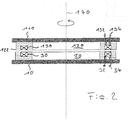
- a complete transformer consists of a first, fixed half 10 and a rotatable relative to this half.
- the verdehbare half consists of base 110 and core 120 with core sheets 122, etc., and the coil 130.
- the rotation of the half 110 takes place relative to the figure axis 140.
- the figure axes of halves 10 and 110 are suitably parallel and ideally coincide.
- the first and the second half are preferably constructed completely comparable.
- the air gap between the cores 20, 120 is dimensioned according to practical conditions and is typical relatively small.
- the inductive coupling between the first and second coil 30, 130 is thus effected substantially by the magnetic flux in the cores 20, 120, which surrounds the coils in a toroidal manner in a conventional manner.
- an alternating voltage for the transmission of information or electrical energy from, for example, the terminals 32, 34 to the terminals 132, 134 are transferred without contact, maW at the terminals 132, 134, a voltage can be tapped or queried
- FIG. 3 The course of the magnetic flux through the core 20, when the coil 30 is energized, is indicated in schematic form in FIG. 3. As shown, the magnetic field lines in the soft magnetic sheets 27, 29 are rather parallel to their surfaces, so induction of secondary stresses can take place only to a small extent in these sheets.
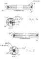
- FIG. 4 The arrangement of a device according to the invention according to FIG. 4 is in principle comparable to the arrangement according to FIG. 2, but has modified carriers 10, 110 of hollow cylindrical shape. (Connections to coils 30, 130 are not shown in Figs. 4 and 5).
- FIG. 5 essentially corresponds to the arrangement from FIG. 4, but instead of insulated steel disks or rings, isolated steel bands (soft iron bands) of hollow cylindrical shape are now provided for the cores 20 ', 120', as clearly shown in detail in FIG of Fig. 5 is shown.
- isolated steel bands soft iron bands
Landscapes
- Engineering & Computer Science (AREA)
- Power Engineering (AREA)
- Computer Networks & Wireless Communication (AREA)
- Coils Or Transformers For Communication (AREA)
- Near-Field Transmission Systems (AREA)
- Arrangements For Transmission Of Measured Signals (AREA)
- Manufacturing Cores, Coils, And Magnets (AREA)
Applications Claiming Priority (2)
| Application Number | Priority Date | Filing Date | Title |
|---|---|---|---|
| DE102005047525 | 2005-10-04 | ||
| DE200510058104 DE102005058104A1 (de) | 2005-12-05 | 2005-12-05 | Rotierübertrager zur Übertragung von elektrischer Energie oder Information |
Publications (2)
| Publication Number | Publication Date |
|---|---|
| EP1772940A2 true EP1772940A2 (fr) | 2007-04-11 |
| EP1772940A3 EP1772940A3 (fr) | 2011-05-18 |
Family
ID=37668194
Family Applications (1)
| Application Number | Title | Priority Date | Filing Date |
|---|---|---|---|
| EP06019747A Withdrawn EP1772940A3 (fr) | 2005-10-04 | 2006-09-21 | Coupleur rotatif pour la transmission d'énergie électrique ou information |
Country Status (2)
| Country | Link |
|---|---|
| US (1) | US7304559B2 (fr) |
| EP (1) | EP1772940A3 (fr) |
Families Citing this family (5)
| Publication number | Priority date | Publication date | Assignee | Title |
|---|---|---|---|---|
| DE10344055A1 (de) * | 2003-09-23 | 2005-04-21 | Siemens Ag | Induktiver Drehübertrager |
| JP2017063567A (ja) * | 2015-09-25 | 2017-03-30 | アイシン精機株式会社 | 無接点給電装置 |
| US10119343B2 (en) | 2016-06-06 | 2018-11-06 | Sanvean Technologies Llc | Inductive coupling |
| US11031164B2 (en) * | 2017-09-29 | 2021-06-08 | Apple Inc. | Attachment devices for inductive interconnection systems |
| DE102018000030B4 (de) * | 2018-01-03 | 2023-03-30 | Hottinger Brüel & Kjaer GmbH | System für drahtloses Versorgen einer rotierenden Vorrichtung mit elektrischer Energie |
Family Cites Families (7)
| Publication number | Priority date | Publication date | Assignee | Title |
|---|---|---|---|---|
| US5272350A (en) * | 1992-10-29 | 1993-12-21 | Baker Hughes Incorporated | Rotary coupler effecting power and information exchange |
| CA2109652A1 (fr) * | 1992-11-25 | 1994-05-26 | Richard J. Becker | Dynamoteur |
| DE29503608U1 (de) * | 1994-06-17 | 1995-09-14 | Schmall, Karl-Heinz, 76532 Baden-Baden | Elektromagnetischer Koppler |
| JPH09213549A (ja) * | 1996-02-07 | 1997-08-15 | Sony Corp | 円筒型ロータリートランス |
| DE10234893A1 (de) * | 2002-07-26 | 2004-02-12 | Sipra Patententwicklungs- Und Beteiligungsgesellschaft Mbh | Vorrichtung mit einem stationären und einem bewegbaren Bauteil und einer Einrichtung zur gleichzeitigen Übertragung von elektrischer Energie und Information zwischen diesen Bauteilen |
| JP3643961B2 (ja) * | 2002-10-09 | 2005-04-27 | ミネベア株式会社 | 回転トランス型レゾルバのインナーコア構造 |
| DE10344055A1 (de) * | 2003-09-23 | 2005-04-21 | Siemens Ag | Induktiver Drehübertrager |
-
2006
- 2006-09-21 EP EP06019747A patent/EP1772940A3/fr not_active Withdrawn
- 2006-10-04 US US11/538,564 patent/US7304559B2/en active Active
Also Published As
| Publication number | Publication date |
|---|---|
| EP1772940A3 (fr) | 2011-05-18 |
| US20070080770A1 (en) | 2007-04-12 |
| US7304559B2 (en) | 2007-12-04 |
Similar Documents
| Publication | Publication Date | Title |
|---|---|---|
| DE69503336T2 (de) | Linearantrieb | |
| EP2463869B1 (fr) | Composant inductif doté de propriétés de noyau améliorées | |
| DE102017207659B4 (de) | Elektrische Maschine sowie Verfahren zum Herstellen einer elektrischen Maschine | |
| EP1629590B1 (fr) | Machine a flux transversal | |
| EP1705673B1 (fr) | Transformateur rotatif inductif | |
| DE102008006140A1 (de) | Abgeschirmte Leistungs-Kopplungs-Vorrichtung | |
| EP2659497A1 (fr) | Bobine plate pour un transfert d'énergie par induction, sans contact | |
| DE102016108646B4 (de) | Elektrodynamische Bremse | |
| WO1999048190A1 (fr) | Moteur a flux transversal polyphase | |
| DE102018122033A1 (de) | Dreiphasentransformator | |
| EP1658668B1 (fr) | Ensemble pour le transfert inductif sans contact d'une puissance electrique | |
| DE2516011A1 (de) | Magnetkupplung zur loesbaren verbindung elektrischer leitungen | |
| EP1772940A2 (fr) | Coupleur rotatif pour la transmission d'énergie électrique ou information | |
| EP2867906B1 (fr) | Composant inductif | |
| DE3108161C2 (de) | Wicklung für einen Transformator bzw. eine Drossel | |
| DE479292C (de) | Verfahren zur Herstellung von Induktionsspulen, vorwiegend fuer Fernsprechzwecke | |
| DE102005058104A1 (de) | Rotierübertrager zur Übertragung von elektrischer Energie oder Information | |
| EP2495742B1 (fr) | Bobine d'antiparasitage à compensation de courant résistant aux tensions élevées | |
| DE1589594C3 (de) | Magnetischer Vierpol mit vier supraleitenden Spulen und Verfahren zur Herstellung einer Spule hierfür | |
| EP0959484A2 (fr) | Blindage pour dispositif transformateur différentiel pour disjoncteur de défaut à la terre | |
| DE10351117B3 (de) | Drehtransformator | |
| DE3906908A1 (de) | Laminierte spule fuer einen mit starkem wechselstrom angetriebenen, wirbelstroeme induzierenden magnetfeld-generator | |
| EP2704167A1 (fr) | Bobine à noyau toroïdal et transducteur équipé d'un tel noyau toroïdal | |
| DE4443999C1 (de) | Permanenterregte Transversalflußmaschine mit einfachem Rotor | |
| DE3903587A1 (de) | Koaxialer induktiver verbinder |
Legal Events
| Date | Code | Title | Description |
|---|---|---|---|
| PUAI | Public reference made under article 153(3) epc to a published international application that has entered the european phase |
Free format text: ORIGINAL CODE: 0009012 |
|
| AK | Designated contracting states |
Kind code of ref document: A2 Designated state(s): AT BE BG CH CY CZ DE DK EE ES FI FR GB GR HU IE IS IT LI LT LU LV MC NL PL PT RO SE SI SK TR |
|
| AX | Request for extension of the european patent |
Extension state: AL BA HR MK YU |
|
| PUAL | Search report despatched |
Free format text: ORIGINAL CODE: 0009013 |
|
| AK | Designated contracting states |
Kind code of ref document: A3 Designated state(s): AT BE BG CH CY CZ DE DK EE ES FI FR GB GR HU IE IS IT LI LT LU LV MC NL PL PT RO SE SI SK TR |
|
| AX | Request for extension of the european patent |
Extension state: AL BA HR MK RS |
|
| AKY | No designation fees paid | ||
| REG | Reference to a national code |
Ref country code: DE Ref legal event code: R108 |
|
| REG | Reference to a national code |
Ref country code: DE Ref legal event code: R108 Effective date: 20120125 |
|
| STAA | Information on the status of an ep patent application or granted ep patent |
Free format text: STATUS: THE APPLICATION IS DEEMED TO BE WITHDRAWN |
|
| 18D | Application deemed to be withdrawn |
Effective date: 20111119 |