EP1772995B1 - System zum Steuern elektrischer Lasten eines Fahrzeugs - Google Patents
System zum Steuern elektrischer Lasten eines Fahrzeugs Download PDFInfo
- Publication number
- EP1772995B1 EP1772995B1 EP05425710A EP05425710A EP1772995B1 EP 1772995 B1 EP1772995 B1 EP 1772995B1 EP 05425710 A EP05425710 A EP 05425710A EP 05425710 A EP05425710 A EP 05425710A EP 1772995 B1 EP1772995 B1 EP 1772995B1
- Authority
- EP
- European Patent Office
- Prior art keywords
- control
- control device
- electrical load
- vehicle
- electrical
- Prior art date
- Legal status (The legal status is an assumption and is not a legal conclusion. Google has not performed a legal analysis and makes no representation as to the accuracy of the status listed.)
- Expired - Lifetime
Links
Images

Classifications
-
- G—PHYSICS
- G08—SIGNALLING
- G08C—TRANSMISSION SYSTEMS FOR MEASURED VALUES, CONTROL OR SIMILAR SIGNALS
- G08C17/00—Arrangements for transmitting signals characterised by the use of a wireless electrical link
- G08C17/02—Arrangements for transmitting signals characterised by the use of a wireless electrical link using a radio link
-
- H—ELECTRICITY
- H04—ELECTRIC COMMUNICATION TECHNIQUE
- H04W—WIRELESS COMMUNICATION NETWORKS
- H04W84/00—Network topologies
- H04W84/18—Self-organising networks, e.g. ad-hoc networks or sensor networks
Definitions
- the present invention relates to a control system for electrical loads of a vehicle.
- the present invention finds advantageous, but not exclusive, application in the automotive field, to which the ensuing treatment will make explicit reference, without this implying any loss of generality.
- Said control devices are generally located in the front part of the passenger compartment of the motor car in a fixed position so as to be conveniently operable by the driver or at the most by the passenger sitting at his side. Consequently, the occupants of the rear seats do not generally have access to any of said control devices, with the exception, in upper-range motor vehicles, of those for operation of the rear power windows, which are generally usually located in the rear door.
- DE10142967 discloses a vehicle which has on-board electronics connected to an interface in the form of a plug connection and/or a wireless connection for exchanging data with a personal digital assistant and to at least one controller that can be controlled by the personal digital assistant depending on an identification code associated with the personal digital assistant.
- GB2120424 discloses an installation for the input, output and processing of data which are significant for the operation of a motor vehicle, which includes a mobile hand-size calculator that is connected with information senders and/or actuating mechanisms by way of a transmission arrangement.
- WO0044591 discloses an interface that communicates with a computer mounted in a vehicle, wherein the interface includes an input device, adapted to be removed from the vehicle, having a first electrical connector.
- a docking site having a second electrical connector adapted to receive the first electrical connector, is mounted in the vehicle for supporting the input device.
- a communication cable connects the second electrical connector to the computer thereby providing a communication path between the input device and the computer.
- the input device includes a transmitter circuit for producing and transmitting wireless control signals. In this manner, the input device may be used to remotely control an electrical accessory device in the vehicle, such as a door lock/unlock motor.
- the input device is used to enable the engine ignition system of the vehicle. In this manner, the vehicle may be started without an ignition key yet still be protected against theft.
- the aim of the present invention is to provide a control system for electrical loads of a vehicle, which will enable the need referred to above to be met.
- the above aim is achieved by the present invention in so far as it relates to a control system for electrical loads of a vehicle, in particular a motor car, as defined in Claim 1.
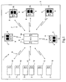
- FIG. 1 Designated as a whole by 1 in Figure 1 is a wireless control system for electrical loads 2 of a vehicle 3 (represented schematically), for example a motor vehicle, in particular a motor car.
- a vehicle 3 represented schematically
- a motor vehicle for example a motor vehicle, in particular a motor car.
- the electrical loads 2 are generically constituted by any electrically controlled device, whether it is an electrical device, for example a headlight, an electronic device, for example a car radio, a satellite navigator, or the like, or else a mechanical/hydraulic/pneumatic device, for example a headlight-washer device, a power-window device, an internal or external rear-view mirror, an electric actuator or an electric motor in general, an air-bag, a pretensioner, or the like.
- an electrical device for example a headlight
- an electronic device for example a car radio, a satellite navigator, or the like
- a mechanical/hydraulic/pneumatic device for example a headlight-washer device, a power-window device, an internal or external rear-view mirror, an electric actuator or an electric motor in general, an air-bag, a pretensioner, or the like.
- control system 1 comprises:
- the second communication system 8 comprises:
- transceiver modules 10 and 11 although described and illustrated as distinct for reasons of convenience, are in actual fact constituted by a single transceiver module such as to enable the electronic control unit 6 to communicate on the one hand with the control devices 4 and on the other with the electrical loads 2.
- the electronic control unit 6 performs the task of receiving the control signals transmitted by the control devices 4, identifying, on the basis thereof, the electrical loads 2 to be actuated, and transmitting said control signals to the corresponding electrical loads 2. Furthermore, the electronic control unit 6 performs the task of receiving any possible state signals transmitted by the electrical loads 2, identifying, on the basis thereof, the control devices 4 to which they are to be sent, and sending said state signals to the corresponding control devices 4, for example for activating possible devices (display, LED) for displaying the operating state of the corresponding electrical load 2.
- control signals transmitted by the control devices 4 and the state signals transmitted by the electrical loads 2 are encoded in a unique way.
- the wireless-communication systems 7 and 8 are both based upon the communication technology known as BluetoothTM, which is particularly indicated for complex connection and control applications and, in addition to being indicated for replacing completely, or at least in part, the connections to the electrical loads 2, also enables hands-free commands (for example commands of a vocal type) to be issued.
- BluetoothTM the communication technology known as BluetoothTM
- the communication protocol and the format of the data packet of BluetoothTM technology is the following:
- the wireless-communication system 8 (and possibly also the wireless-communication system 7) is based upon the communication technology known as ZigBeeTM, which is devised principally for applications of command and control and hence is particularly indicated for replacing completely, or at least in part, the connections to the electrical loads 3.
- ZigBeeTM the communication technology known as ZigBeeTM
- ZigBeeTM technology has a protocol suitable for management of simple devices, with low energy consumption and involving a high number of nodes, whilst BluetoothTM technology is used for those applications that require a greater data-transfer capacity.
- the communication protocol and the format of the data packet of ZigBeeTM technology is the following:
- the electronic control unit 6 must possibly be configured for converting the control signals coming from the control devices 4 and encoded according to the protocol of the first wireless-communication system 7 (BluetoothTM, in the example) into the format recognized by the second wireless-communication system 8 (ZigBeeTM, in the example).
- each housing seat 5 is provided with a pair of electrical contacts 13 connected to an external electric-power source (not illustrated), for example the battery of the motor car, and is configured for receiving and withholding in a releasable way a respective control device 4.
- an external electric-power source not illustrated
- each housing seat 5 could be provided with a fixing mechanism of the snap-action type or of the interference-fit type or else of a magnetic type, or any other known mechanism suitable for the purpose, configured for cooperating with a complementary mechanism carried by the control device 4.
- Each control device 4 comprises a casing 14 configured in such a way as to enable stable fixing of the control device 4 within the respective housing seat 5 and its simple removal from said housing seat 5; in particular, it is provided with a fixing mechanism configured so as to co-operate with the one provided in the housing seat 5 for withholding the control device 4 within the housing seat 5 itself.
- the casing 14 of the control device 4 moreover carries:
- the control device 4 is supplied by the battery of the motor car 3 when it is set in the corresponding housing seat 5, whilst it is supplied by the autonomous supply device 16 when it is removed from the corresponding housing seat 5, thus functioning in the wireless mode both when it is inserted in the corresponding housing seat 5 and when it is removed therefrom, operating, in the latter case, practically like a remote control through which it is possible to actuate the corresponding electrical load 2.
- the driver of the motor car 3 or the passenger at his side can at any moment take a control device 4 out of the corresponding housing seat 5 and "pass it" to one of the occupants of the rear seats, who can then activate/de-activate, and more in general interact with, the electrical load 2 controlled by said control device 4.
- This function of remote control of the control devices 4 proves particularly useful, for example, for enabling the occupants of the rear seats to operate the rear power windows of the motor car via control devices 4 that the manufacturer of the motor car has placed, for other reasons, in the front part of the motor car 3, or else to enable the occupants of the rear seats to interact with the car radio, which, as is known, is typically set on the dashboard of the motor car, it being thus possible to turn the volume up or down, change station or piece of music, etc.
- the shapes and dimensions of the housing seats 5 and of the casings 14 of the control devices 4 are designed to enable removable location of some or all the control devices 4 also in housing seats 5 different from the ones that the manufacturer had envisaged for them in the stage of design of the motor car 3.
- the shapes and dimensions of the housing seats 5 and of the casings 14 of the control devices 4 could be designed according to a principle of modularity, and inside the passenger compartment of the car 3 there could be provided a number of housing seats 5 such as to enable placing of some or all of the control devices in a number of points of the passenger compartment of the car.
- a number of seats 5 for housing the control push-buttons for operating the power windows could be provided, for example, four in the central tunnel and other four in the doors, a number of seats for housing the knob for adjustment of the position of the external rear-view mirrors, for example one in the front right door and one in the central tunnel, a number of seats for housing the front panel of the car radio, for example one in the front part and one in the rear part of the passenger compartment, a number of seats for housing the knobs and/or push-buttons for adjusting the air-conditioning system, for example, one in the front part and one in the rear part of the passenger compartment, and so forth.
- the driver and/or passengers of the motor car 3 can modify the arrangement of the control devices 4 when they buy the car 3 itself according to his/their own habits or to specific requirements deriving from particular physical conditions.
- the four control push-buttons 4 of the front and rear right and left power windows provided initially by the manufacturer in the central tunnel of the motor car can, for example, be displaced onto the front and rear right and left doors, in such a way as to allow all the occupants of the vehicle to control their own power windows, as likewise the knobs and/or push-buttons for adjusting the air-conditioning system can be displaced into the housing seats provided in the rear part of the motor car, or else the front panel of the car radio can be displaced into the housing seat provided in the rear part of the motor car, etc.
- the present invention enables the occupants of the rear seats of a motor car to actuate all the electrical loads that are not strictly linked to driving, without disturbing the driver and without requiring a duplication of the control devices, with consequent benefits in terms of costs of the motor car and of safety of driving.
- the present invention enables a high flexibility in the personalization of the inside of the motor car, with consequent benefits in terms of passenger comfort.
- all the electrical loads 2 could be controlled, instead of via a single electronic control unit 6, through a number of distinct interconnection devices, or else be connected to the electronic control unit 6 in a wired, instead of wireless, way.
- wireless communication technologies used may be different from those described.
- medium-range or long-range wireless-communication technologies could be employed, such as for example Wi-Fi, IrDA (infrared), etc.
- the transceiver modules provided on the control devices 4 and on the electrical loads 2 can be replaced with transmitting modules present on the control devices 4 and with receiving modules present on the electrical loads.
- control system according to the invention could be used not only on motor vehicles, but on any type of vehicle, for example ships, trains, planes, etc.
Landscapes
- Engineering & Computer Science (AREA)
- Computer Networks & Wireless Communication (AREA)
- Physics & Mathematics (AREA)
- General Physics & Mathematics (AREA)
- Selective Calling Equipment (AREA)
- Control Of Eletrric Generators (AREA)
Claims (10)
- Ein Steuersystem (1) zum Steuern einer elektrischen Last (2) eines Fahrzeugs (3), wobei das Steuersystem (1) umfasst:• ein drahtloses Steuergerät (4) zum Steuern der elektrischen Last, wobei das Steuergerät (4) konfiguriert ist zum entfernbaren Anbringen in einem Gehäusesitz (5), bereitgestellt in dem Fahrzeug (3), und zum Arbeiten, selbst wenn von dem Gehäusesitz (5) entfernt;• ein elektronisches Steuermittel (6), konfiguriert zum Steuern der elektrischen Last (2);• ein erstes drahtloses Kommunikationssystem (7), konfiguriert zum Ermöglichen einer Kommunikation zwischen dem Steuergerät (4) und dem elektronischen Steuermittel (6); und• ein zweites drahtloses Kommunikationssystem (8), konfiguriert zum Ermöglichen einer Kommunikation zwischen dem elektronischen Steuermittel (6) und der elektrischen Last (2);wobei das erste drahtlose Kommunikationssystem (7) umfasst:• ein erstes Übertragungsmittel (9), getragen von dem Steuergerät (4) zum Übertragen an das elektronische Steuermittel (6) von Steuersignalen für die elektrische Last (2), und erzeugt durch das Steuergerät (4);• ein erstes Empfangsmittel (10), getragen durch das elektronische Steuermittel (6) zum Empfangen von Steuersignalen für die elektrische Last (2) und Übertragen durch das Steuergerät (4);und wobei das zweite drahtlose Kommunikationssystem (8) umfasst:• ein zweites Übertragungsmittel (11), getragen von dem elektronischen Steuermittel (6) zum Übertragen an die elektrische Last (2) von den Steuersignalen, die übertragen werden von dem Steuergerät (4); und• ein zweites Empfangsmittel (12), getragen von der elektrischen Last (2) zum Empfangen der Steuersignale, die übertragen werden von dem elektronischen Steuermittel (6);wobei das zweite drahtlose Kommunikationssystem (8) ferner umfasst:• ein drittes Übertragungsmittel (12), getragen von der elektrischen Last (2) zum Übertragen von Zustandssignalen, die einen Betriebszustand der elektrischen Last (2) kennzeichnen; und• ein drittes Empfangsmittel (11), getragen von dem elektronischen Steuermittel (6) zum Empfangen der Zustandssignale, die übertragen werden von der elektrischen Last (2);und wobei das erste drahtlose Kommunikationssystem (7) ferner umfasst:• ein viertes Übertragungsmittel (10), getragen von dem elektronischen Steuermittel (6) zum Übertragen an das Steuergerät (4) der Zustandssignale, die übertragen werden durch die elektrische Last (2); und• ein viertes Empfangsmittel (9), getragen von dem Steuergerät (4) zum Empfangen der Zustandssignale, die übertragen werden von dem elektronischen Steuermittel (6);wobei das Steuergerät (4) ein Anzeigemittel (15) umfasst, das betriebsfähig ist zum Anzeigen des Betriebszustands der elektrischen Last (2).
- Das System nach Anspruch 1, wobei das erste und zweite Kommunikationssystem (7, 8) auf mindestens einer der folgenden Technologien basiert, Bluetooth, ZigBee und Wi-Fi.
- Das System nach Anspruch 1 oder 2, wobei das Steuergerät (4) ferner umfasst:• ein Mensch-Maschine-Schnittstellenmittel (15), konfiguriert zum Ermöglichen eines Benutzers, die elektrische Last (2) zu steuern; und• ein elektrisches Versorgungsmittel (16, 17, 18), konfiguriert zum Ermöglichen eines Betriebs des Steuergeräts (4), wenn beide angeordnet sind in und entfernt werden von dem Gehäusesitz (5).
- Das System nach Anspruch 3, wobei das elektrische Versorgungsmittel (16, 17) umfasst:• ein autonomes elektrisches Versorgungsmittel (16); und• ein elektrisches Verbindungsmittel (13, 17, 18), konfiguriert zum Verbinden des Steuergeräts (4) mit einer elektrischen Leistungsquelle des Fahrzeugs (3), und zum Wiederaufladen des autonomen elektrischen Versorgungsmittels (16), wenn das Steuergerät (4) angeordnet ist in dem Gehäusesitz (5).
- Das System nach Anspruch 4, wobei der Gehäusesitz (5) umfasst:• ein elektrisches Verbindungsmittel (13), konfiguriert zum Verbinden des Steuergeräts (4) mit der elektrischen Leistungsquelle des Fahrzeugs (3).
- Das System nach einem der Ansprüche 3 bis 5, wobei das Mensch-Maschine-Schnittstellenmittel (15) umfasst:• mindestens ein Steuerelement (15), betriebsfähig zum Steuern der elektrischen Last (2).
- Das System nach einem der vorhergehenden Ansprüche, umfassend mindestens einen weiteren Gehäusesitz (5), bereitgestellt in dem Fahrzeug (3), und wobei der Gehäusesitz (5) und das Steuergerät (4) derart gebildet sind, dass eine entfernbare Anordnung des Steuergeräts (4) auch in dem weiteren Gehäusesitz (5) ermöglicht wird.
- Ein Fahrzeug (3), umfassend mindestens eine elektrische Last (2) und ein Steuersystem (1) zum Steuern der elektrischen Last (2) gemäß einem der vorhergehenden Ansprüche.
- Das Fahrzeug nach Anspruch 8, wobei das Fahrzeug ein Motorfahrzeug ist.
- Das Fahrzeug nach Anspruch 9, wobei das Fahrzeug ein Automobil ist.
Priority Applications (4)
| Application Number | Priority Date | Filing Date | Title |
|---|---|---|---|
| AT05425710T ATE432569T1 (de) | 2005-10-10 | 2005-10-10 | System zum steuern elektrischer lasten eines fahrzeugs |
| DE602005014645T DE602005014645D1 (de) | 2005-10-10 | 2005-10-10 | System zum Steuern elektrischer Lasten eines Fahrzeugs |
| EP05425710A EP1772995B1 (de) | 2005-10-10 | 2005-10-10 | System zum Steuern elektrischer Lasten eines Fahrzeugs |
| US11/545,717 US7791219B2 (en) | 2005-10-10 | 2006-10-10 | Control system for electrical loads of a vehicle |
Applications Claiming Priority (1)
| Application Number | Priority Date | Filing Date | Title |
|---|---|---|---|
| EP05425710A EP1772995B1 (de) | 2005-10-10 | 2005-10-10 | System zum Steuern elektrischer Lasten eines Fahrzeugs |
Publications (2)
| Publication Number | Publication Date |
|---|---|
| EP1772995A1 EP1772995A1 (de) | 2007-04-11 |
| EP1772995B1 true EP1772995B1 (de) | 2009-05-27 |
Family
ID=35759325
Family Applications (1)
| Application Number | Title | Priority Date | Filing Date |
|---|---|---|---|
| EP05425710A Expired - Lifetime EP1772995B1 (de) | 2005-10-10 | 2005-10-10 | System zum Steuern elektrischer Lasten eines Fahrzeugs |
Country Status (4)
| Country | Link |
|---|---|
| US (1) | US7791219B2 (de) |
| EP (1) | EP1772995B1 (de) |
| AT (1) | ATE432569T1 (de) |
| DE (1) | DE602005014645D1 (de) |
Cited By (1)
| Publication number | Priority date | Publication date | Assignee | Title |
|---|---|---|---|---|
| DE102017002817A1 (de) * | 2016-12-29 | 2018-07-05 | Valmet Automotive Oy | Verdeckvorrichtung eines Cabriolet-Fahrzeugs |
Families Citing this family (9)
| Publication number | Priority date | Publication date | Assignee | Title |
|---|---|---|---|---|
| US7560827B2 (en) * | 2006-10-31 | 2009-07-14 | Lear Corporation | Removable seat sensing system |
| DE102007010888B4 (de) * | 2007-03-06 | 2010-03-04 | Continental Automotive Gmbh | Steuergerät zur drahtlosen Kommunikation mit einer peripheren Einheit |
| DE102007041257A1 (de) * | 2007-08-30 | 2009-03-12 | Continental Automotive Gmbh | Vorrichtung zur Halterung von verschiedenen Modulen |
| JP2009062688A (ja) * | 2007-09-04 | 2009-03-26 | Tokai Rika Co Ltd | 車両用通信システム |
| DE102007042675B4 (de) * | 2007-09-10 | 2013-04-04 | Continental Automotive Gmbh | Kraftfahrzeug mit einem Multimediasystem |
| DE102011119543B4 (de) | 2011-11-26 | 2024-09-26 | Volkswagen Aktiengesellschaft | Modulsystem zur Fahrzeugbedienung |
| US10007478B2 (en) * | 2015-06-26 | 2018-06-26 | Ford Global Technologies, Llc | System and methods for voice-controlled seat adjustment |
| JP6912952B2 (ja) * | 2017-06-26 | 2021-08-04 | 本田技研工業株式会社 | 車両操作装置 |
| CN109866717A (zh) * | 2019-03-26 | 2019-06-11 | 重庆长安汽车股份有限公司 | 一种自定义车辆负载触发功能的控制方法、装置及汽车 |
Citations (1)
| Publication number | Priority date | Publication date | Assignee | Title |
|---|---|---|---|---|
| US20050127122A1 (en) * | 2003-12-12 | 2005-06-16 | Lear Corporation | Universal Feature Attachment System |
Family Cites Families (10)
| Publication number | Priority date | Publication date | Assignee | Title |
|---|---|---|---|---|
| DE3211691A1 (de) * | 1982-03-30 | 1983-10-06 | Porsche Ag | Einrichtung zur aufnahme, abgabe und verarbeitung von daten |
| US6144114A (en) * | 1998-03-25 | 2000-11-07 | Lear Automotive Dearborn, Inc. | Auto PC wallet PC faceplate |
| DE10040238A1 (de) * | 2000-08-17 | 2002-03-07 | Siemens Ag | Anordnung und Verfahren zur Signalübertragung in Fahrzeugen |
| US6700310B2 (en) * | 2000-10-13 | 2004-03-02 | Lear Corporation | Self-powered wireless switch |
| US6805455B2 (en) * | 2001-06-29 | 2004-10-19 | N-K Enterprises, Llc | Wireless remote controlled mirror with integral lighting |
| DE10142967A1 (de) * | 2001-09-01 | 2003-03-27 | Opel Adam Ag | Kraftfahrzeug mit einer Bordelektronik |
| JP3812459B2 (ja) * | 2002-02-26 | 2006-08-23 | トヨタ自動車株式会社 | 車両の電源制御装置 |
| DE10212039A1 (de) * | 2002-03-19 | 2003-10-02 | Zahnradfabrik Friedrichshafen | Drahtlose Kommunikation in Fahrzeugen |
| JP3988618B2 (ja) * | 2002-10-30 | 2007-10-10 | 株式会社デンソー | 車両の遠隔制御装置 |
| DE202004007932U1 (de) * | 2004-05-17 | 2005-09-22 | Peter, Andreas | System zum Steuern von Fahrzeugfunktionen mittels einer tragbaren Bedieneinheit |
-
2005
- 2005-10-10 AT AT05425710T patent/ATE432569T1/de not_active IP Right Cessation
- 2005-10-10 EP EP05425710A patent/EP1772995B1/de not_active Expired - Lifetime
- 2005-10-10 DE DE602005014645T patent/DE602005014645D1/de not_active Expired - Lifetime
-
2006
- 2006-10-10 US US11/545,717 patent/US7791219B2/en active Active
Patent Citations (1)
| Publication number | Priority date | Publication date | Assignee | Title |
|---|---|---|---|---|
| US20050127122A1 (en) * | 2003-12-12 | 2005-06-16 | Lear Corporation | Universal Feature Attachment System |
Cited By (2)
| Publication number | Priority date | Publication date | Assignee | Title |
|---|---|---|---|---|
| DE102017002817A1 (de) * | 2016-12-29 | 2018-07-05 | Valmet Automotive Oy | Verdeckvorrichtung eines Cabriolet-Fahrzeugs |
| DE102017002817B4 (de) | 2016-12-29 | 2023-05-17 | Valmet Automotive Oy | Verdeckvorrichtung eines Cabriolet-Fahrzeugs |
Also Published As
| Publication number | Publication date |
|---|---|
| US20070090967A1 (en) | 2007-04-26 |
| US7791219B2 (en) | 2010-09-07 |
| EP1772995A1 (de) | 2007-04-11 |
| DE602005014645D1 (de) | 2009-07-09 |
| ATE432569T1 (de) | 2009-06-15 |
Similar Documents
| Publication | Publication Date | Title |
|---|---|---|
| EP2211310B1 (de) | Zweifach verwendbare drahtlose vorrichtung | |
| EP1147034B1 (de) | Schnittstelle für die kommunikation mit einem fahrzeug-rechner | |
| US9981615B2 (en) | Remote function control system for a vehicle having a data communications bus and related methods | |
| US6639519B2 (en) | Vehicular rearview mirror system | |
| US7725129B2 (en) | Cell phone based vehicle control system | |
| US20100198428A1 (en) | Multi-purpose fob system | |
| EP3957523B1 (de) | Integrierter chip, fahrzeugsteuerungssystem und vorrichtung sowie fahrzeug | |
| US9527478B2 (en) | Remote function control system for a vehicle having a data communications bus and related methods | |
| US11142165B2 (en) | Vehicle system including remote start data bus command sending based upon a short-range link and related methods | |
| US7791219B2 (en) | Control system for electrical loads of a vehicle | |
| US9919682B2 (en) | Remote function device and associated wireless security sensor for a vehicle having a data communications bus and related methods | |
| US9656631B1 (en) | Remote function control system with wireless databus device and associated wireless security sensor for a vehicle having a data communications bus and related methods | |
| CA2951679C (en) | Remote function control system with remote function device and associated wireless security sensor for a vehicle having a data communications bus and related methods | |
| EP1627778B1 (de) | Kraftfahrzeug mit 2 drahtlose Netzwerke und einer beide Netzwerke verbindendes Gateway | |
| JP4601337B2 (ja) | 車載通信システム及び通信制御機能付きコネクタ装置 | |
| EP3998178A1 (de) | Stromversorgungssystem in einem fahrzeug | |
| WO2006112161A1 (ja) | 車載通信装置およびその方法 | |
| CA2925135C (en) | Remote function control system for a vehicle having a data communications bus and related methods | |
| JPH06276571A (ja) | 多重伝送装置 | |
| JP4134677B2 (ja) | 情報提供装置 | |
| JP2005170338A (ja) | 車両用情報通信装置 | |
| EP1918161B1 (de) | Steuersystem für elektrische Geräte eines Kraftfahrzeuges | |
| KR101073902B1 (ko) | 차량 원격제어장치 | |
| JP2005081861A (ja) | 車載制御システム | |
| JP2005075267A (ja) | 車内制御システム |
Legal Events
| Date | Code | Title | Description |
|---|---|---|---|
| PUAI | Public reference made under article 153(3) epc to a published international application that has entered the european phase |
Free format text: ORIGINAL CODE: 0009012 |
|
| 17P | Request for examination filed |
Effective date: 20061206 |
|
| AK | Designated contracting states |
Kind code of ref document: A1 Designated state(s): AT BE BG CH CY CZ DE DK EE ES FI FR GB GR HU IE IS IT LI LT LU LV MC NL PL PT RO SE SI SK TR |
|
| AX | Request for extension of the european patent |
Extension state: AL BA HR MK YU |
|
| 17Q | First examination report despatched |
Effective date: 20070613 |
|
| AKX | Designation fees paid |
Designated state(s): AT BE BG CH CY CZ DE DK EE ES FI FR GB GR HU IE IS IT LI LT LU LV MC NL PL PT RO SE SI SK TR |
|
| GRAP | Despatch of communication of intention to grant a patent |
Free format text: ORIGINAL CODE: EPIDOSNIGR1 |
|
| GRAS | Grant fee paid |
Free format text: ORIGINAL CODE: EPIDOSNIGR3 |
|
| GRAA | (expected) grant |
Free format text: ORIGINAL CODE: 0009210 |
|
| RIN1 | Information on inventor provided before grant (corrected) |
Inventor name: SAVIO, WALTER,C/O C.R.F. SOCIETA CONSORTILE PER AZ Inventor name: ZUCCOTTI, SAVERIO,C/O C.R.F. SOCIETA CONSORTILE PE |
|
| AK | Designated contracting states |
Kind code of ref document: B1 Designated state(s): AT BE BG CH CY CZ DE DK EE ES FI FR GB GR HU IE IS IT LI LT LU LV MC NL PL PT RO SE SI SK TR |
|
| REG | Reference to a national code |
Ref country code: GB Ref legal event code: FG4D |
|
| REG | Reference to a national code |
Ref country code: CH Ref legal event code: EP |
|
| REG | Reference to a national code |
Ref country code: IE Ref legal event code: FG4D |
|
| REF | Corresponds to: |
Ref document number: 602005014645 Country of ref document: DE Date of ref document: 20090709 Kind code of ref document: P |
|
| PG25 | Lapsed in a contracting state [announced via postgrant information from national office to epo] |
Ref country code: PT Free format text: LAPSE BECAUSE OF FAILURE TO SUBMIT A TRANSLATION OF THE DESCRIPTION OR TO PAY THE FEE WITHIN THE PRESCRIBED TIME-LIMIT Effective date: 20090927 Ref country code: AT Free format text: LAPSE BECAUSE OF FAILURE TO SUBMIT A TRANSLATION OF THE DESCRIPTION OR TO PAY THE FEE WITHIN THE PRESCRIBED TIME-LIMIT Effective date: 20090527 Ref country code: FI Free format text: LAPSE BECAUSE OF FAILURE TO SUBMIT A TRANSLATION OF THE DESCRIPTION OR TO PAY THE FEE WITHIN THE PRESCRIBED TIME-LIMIT Effective date: 20090527 Ref country code: LT Free format text: LAPSE BECAUSE OF FAILURE TO SUBMIT A TRANSLATION OF THE DESCRIPTION OR TO PAY THE FEE WITHIN THE PRESCRIBED TIME-LIMIT Effective date: 20090527 |
|
| NLV1 | Nl: lapsed or annulled due to failure to fulfill the requirements of art. 29p and 29m of the patents act | ||
| PG25 | Lapsed in a contracting state [announced via postgrant information from national office to epo] |
Ref country code: PL Free format text: LAPSE BECAUSE OF FAILURE TO SUBMIT A TRANSLATION OF THE DESCRIPTION OR TO PAY THE FEE WITHIN THE PRESCRIBED TIME-LIMIT Effective date: 20090527 Ref country code: SE Free format text: LAPSE BECAUSE OF FAILURE TO SUBMIT A TRANSLATION OF THE DESCRIPTION OR TO PAY THE FEE WITHIN THE PRESCRIBED TIME-LIMIT Effective date: 20090827 Ref country code: IS Free format text: LAPSE BECAUSE OF FAILURE TO SUBMIT A TRANSLATION OF THE DESCRIPTION OR TO PAY THE FEE WITHIN THE PRESCRIBED TIME-LIMIT Effective date: 20090927 Ref country code: SI Free format text: LAPSE BECAUSE OF FAILURE TO SUBMIT A TRANSLATION OF THE DESCRIPTION OR TO PAY THE FEE WITHIN THE PRESCRIBED TIME-LIMIT Effective date: 20090527 Ref country code: NL Free format text: LAPSE BECAUSE OF FAILURE TO SUBMIT A TRANSLATION OF THE DESCRIPTION OR TO PAY THE FEE WITHIN THE PRESCRIBED TIME-LIMIT Effective date: 20090527 Ref country code: LV Free format text: LAPSE BECAUSE OF FAILURE TO SUBMIT A TRANSLATION OF THE DESCRIPTION OR TO PAY THE FEE WITHIN THE PRESCRIBED TIME-LIMIT Effective date: 20090527 |
|
| PG25 | Lapsed in a contracting state [announced via postgrant information from national office to epo] |
Ref country code: RO Free format text: LAPSE BECAUSE OF FAILURE TO SUBMIT A TRANSLATION OF THE DESCRIPTION OR TO PAY THE FEE WITHIN THE PRESCRIBED TIME-LIMIT Effective date: 20090527 Ref country code: DK Free format text: LAPSE BECAUSE OF FAILURE TO SUBMIT A TRANSLATION OF THE DESCRIPTION OR TO PAY THE FEE WITHIN THE PRESCRIBED TIME-LIMIT Effective date: 20090527 Ref country code: EE Free format text: LAPSE BECAUSE OF FAILURE TO SUBMIT A TRANSLATION OF THE DESCRIPTION OR TO PAY THE FEE WITHIN THE PRESCRIBED TIME-LIMIT Effective date: 20090527 Ref country code: ES Free format text: LAPSE BECAUSE OF FAILURE TO SUBMIT A TRANSLATION OF THE DESCRIPTION OR TO PAY THE FEE WITHIN THE PRESCRIBED TIME-LIMIT Effective date: 20090907 Ref country code: CZ Free format text: LAPSE BECAUSE OF FAILURE TO SUBMIT A TRANSLATION OF THE DESCRIPTION OR TO PAY THE FEE WITHIN THE PRESCRIBED TIME-LIMIT Effective date: 20090527 |
|
| PG25 | Lapsed in a contracting state [announced via postgrant information from national office to epo] |
Ref country code: SK Free format text: LAPSE BECAUSE OF FAILURE TO SUBMIT A TRANSLATION OF THE DESCRIPTION OR TO PAY THE FEE WITHIN THE PRESCRIBED TIME-LIMIT Effective date: 20090527 Ref country code: BE Free format text: LAPSE BECAUSE OF FAILURE TO SUBMIT A TRANSLATION OF THE DESCRIPTION OR TO PAY THE FEE WITHIN THE PRESCRIBED TIME-LIMIT Effective date: 20090527 |
|
| PG25 | Lapsed in a contracting state [announced via postgrant information from national office to epo] |
Ref country code: BG Free format text: LAPSE BECAUSE OF FAILURE TO SUBMIT A TRANSLATION OF THE DESCRIPTION OR TO PAY THE FEE WITHIN THE PRESCRIBED TIME-LIMIT Effective date: 20090827 |
|
| PLBE | No opposition filed within time limit |
Free format text: ORIGINAL CODE: 0009261 |
|
| STAA | Information on the status of an ep patent application or granted ep patent |
Free format text: STATUS: NO OPPOSITION FILED WITHIN TIME LIMIT |
|
| 26N | No opposition filed |
Effective date: 20100302 |
|
| PG25 | Lapsed in a contracting state [announced via postgrant information from national office to epo] |
Ref country code: MC Free format text: LAPSE BECAUSE OF NON-PAYMENT OF DUE FEES Effective date: 20091031 |
|
| REG | Reference to a national code |
Ref country code: CH Ref legal event code: PL |
|
| PG25 | Lapsed in a contracting state [announced via postgrant information from national office to epo] |
Ref country code: IE Free format text: LAPSE BECAUSE OF NON-PAYMENT OF DUE FEES Effective date: 20091010 Ref country code: CH Free format text: LAPSE BECAUSE OF NON-PAYMENT OF DUE FEES Effective date: 20091031 Ref country code: LI Free format text: LAPSE BECAUSE OF NON-PAYMENT OF DUE FEES Effective date: 20091031 Ref country code: GR Free format text: LAPSE BECAUSE OF FAILURE TO SUBMIT A TRANSLATION OF THE DESCRIPTION OR TO PAY THE FEE WITHIN THE PRESCRIBED TIME-LIMIT Effective date: 20090828 |
|
| PG25 | Lapsed in a contracting state [announced via postgrant information from national office to epo] |
Ref country code: GB Free format text: LAPSE BECAUSE OF NON-PAYMENT OF DUE FEES Effective date: 20091010 |
|
| PG25 | Lapsed in a contracting state [announced via postgrant information from national office to epo] |
Ref country code: LU Free format text: LAPSE BECAUSE OF NON-PAYMENT OF DUE FEES Effective date: 20091010 |
|
| PG25 | Lapsed in a contracting state [announced via postgrant information from national office to epo] |
Ref country code: HU Free format text: LAPSE BECAUSE OF FAILURE TO SUBMIT A TRANSLATION OF THE DESCRIPTION OR TO PAY THE FEE WITHIN THE PRESCRIBED TIME-LIMIT Effective date: 20091128 |
|
| PG25 | Lapsed in a contracting state [announced via postgrant information from national office to epo] |
Ref country code: TR Free format text: LAPSE BECAUSE OF FAILURE TO SUBMIT A TRANSLATION OF THE DESCRIPTION OR TO PAY THE FEE WITHIN THE PRESCRIBED TIME-LIMIT Effective date: 20090527 |
|
| PG25 | Lapsed in a contracting state [announced via postgrant information from national office to epo] |
Ref country code: CY Free format text: LAPSE BECAUSE OF FAILURE TO SUBMIT A TRANSLATION OF THE DESCRIPTION OR TO PAY THE FEE WITHIN THE PRESCRIBED TIME-LIMIT Effective date: 20090527 |
|
| REG | Reference to a national code |
Ref country code: FR Ref legal event code: PLFP Year of fee payment: 12 |
|
| REG | Reference to a national code |
Ref country code: FR Ref legal event code: PLFP Year of fee payment: 13 |
|
| REG | Reference to a national code |
Ref country code: FR Ref legal event code: PLFP Year of fee payment: 14 |
|
| PGFP | Annual fee paid to national office [announced via postgrant information from national office to epo] |
Ref country code: FR Payment date: 20220920 Year of fee payment: 18 |
|
| PGFP | Annual fee paid to national office [announced via postgrant information from national office to epo] |
Ref country code: IT Payment date: 20220920 Year of fee payment: 18 Ref country code: DE Payment date: 20220920 Year of fee payment: 18 |
|
| REG | Reference to a national code |
Ref country code: DE Ref legal event code: R119 Ref document number: 602005014645 Country of ref document: DE |
|
| PG25 | Lapsed in a contracting state [announced via postgrant information from national office to epo] |
Ref country code: FR Free format text: LAPSE BECAUSE OF NON-PAYMENT OF DUE FEES Effective date: 20231031 Ref country code: DE Free format text: LAPSE BECAUSE OF NON-PAYMENT OF DUE FEES Effective date: 20240501 |
|
| PG25 | Lapsed in a contracting state [announced via postgrant information from national office to epo] |
Ref country code: IT Free format text: LAPSE BECAUSE OF NON-PAYMENT OF DUE FEES Effective date: 20231010 |
|
| PG25 | Lapsed in a contracting state [announced via postgrant information from national office to epo] |
Ref country code: IT Free format text: LAPSE BECAUSE OF NON-PAYMENT OF DUE FEES Effective date: 20231010 |