EP1773215B2 - Chirurgisches schneidinstrument - Google Patents
Chirurgisches schneidinstrument Download PDFInfo
- Publication number
- EP1773215B2 EP1773215B2 EP05772204.3A EP05772204A EP1773215B2 EP 1773215 B2 EP1773215 B2 EP 1773215B2 EP 05772204 A EP05772204 A EP 05772204A EP 1773215 B2 EP1773215 B2 EP 1773215B2
- Authority
- EP
- European Patent Office
- Prior art keywords
- cutting
- cutting edges
- head part
- cutting instrument
- tube
- Prior art date
- Legal status (The legal status is an assumption and is not a legal conclusion. Google has not performed a legal analysis and makes no representation as to the accuracy of the status listed.)
- Expired - Lifetime
Links
Images


Classifications
-
- A—HUMAN NECESSITIES
- A61—MEDICAL OR VETERINARY SCIENCE; HYGIENE
- A61B—DIAGNOSIS; SURGERY; IDENTIFICATION
- A61B17/00—Surgical instruments, devices or methods
- A61B17/32—Surgical cutting instruments
- A61B17/320016—Endoscopic cutting instruments, e.g. arthroscopes, resectoscopes
- A61B17/32002—Endoscopic cutting instruments, e.g. arthroscopes, resectoscopes with continuously rotating, oscillating or reciprocating cutting instruments
Definitions
- the present invention relates to a surgical cutting instrument according to the preamble of patent claim 1.
- Surgical cutting instruments for use in closed or endoscopic surgery are, for example EP 0 557 044 or US-B-6 217 598 known, the document US-B-6 217 598 the features defined in the preamble of claim 1 disclosed. They consist of two telescoped tubes, at which at one end in the end of the so-called “cutting head” and at the other end is a coupling for connection to the drive turbine. The end pieces are open or closed to the front and also have forwardly directed side openings through which rinsing fluid and tissue removed during the procedure is removed.
- the tubes of such instruments are of small diameter and long length, to allow without major surgical wounds, to allow intervention in the body. It usually works by means of three openings in the tissue, but in the closed area of the tissue. Through the first opening, a work-viewing camera is inserted into the body via the screen, the second opening provides access for the surgical cutting instruments, and a nozzle is introduced through a third opening. Through this nozzle brings rinsing, liquid to the work area at the site of the actual procedure. This rinse liquid is removed from the body together with the severed tissue through the tubular center of the cutting tool.
- the femur and pelvis are spread apart by an invasive distractor or by simple stretching in the frame where tendons, ligaments, nerves and muscles allow this.
- the camera is used to monitor the working field via television screens during the operation.
- the working area is kept clean with the rinsing liquid and on the other hand the parts separated with the cutting instrument are sucked off the working area with the rinsing liquid.
- the combined device camera with liquid supply makes it possible to work with only two points of engagement. In some cases the combination of liquid-delivery camera is not possible for practical reasons, e.g. because you want to attach the camera for operational reasons elsewhere in order to have a very specific insight into the field of work.
- the surgical cutting instruments on which the invention is based are designed as long tubes as described above. Through the inside, rotating tube, the rinsing liquid is sucked together with the separated parts.
- Important problems to be solved for the production of such surgical cutting instruments are manufacturing technology, choice of materials and economy. Suitable, sterilizable material must be processed in such a way that, when economically produced, a cutting instrument that is as precise as possible is produced. Normally such instruments are made of high quality metallic alloys.
- the surgical cutting instrument To be able to work with the surgical cutting instrument as efficiently as possible, it should have sharp cutting edges.
- the most difficult requirement for the surgical cutting instrument arises from the need to cut and remove various tissue structures in the same procedure.
- a cutting tool for brittle and hard material is not easily and naturally suitable for cutting elastic, fibrous or plastically soft materials. However, this is precisely what the surgeon desires to be able to carry out the procedure in a short time and efficiently.
- the present invention now has the object to improve a surgical cutting instrument of the type mentioned in such a way that it meets the harsh conditions for in vivo application without problems and the surgeon can serve a really sharp cutting instrument for all types of tissue and bone.
- a surgical cutting instrument of the prior art of this invention consists of a fixed outer tube 10 (FIG. Fig. 1 ) and an inner tube 20 (FIG. Fig. 2 ).
- the entire cutting instrument is connected to a drive provided for this purpose, so that the inner tube 20 can usually be rotated by a turbine drive and, at the same time, suction is ensured through the center of the tubular instrument by means of a vacuum.
- Such devices are widely used in arthroscopic treatment by means of minor surgical procedures.
- outer tube 10 and outer head piece 11 are made in one piece. This also applies to the inner tube 20 and the inner head piece 21. Since in the clinical application such instruments must be clean and sterile without blame, special alloys are used for the production. The sophisticated technique for welding such materials and material thicknesses is the reason why the tubes are usually made in one piece. The inventor has now developed methods which secure welding between outer tube 10 and outer head piece 11 (FIG. Fig. 3 ), as well as between inner tube 20 and inner head piece 21 (FIG. Fig. 4 ) enable. This will allow other machining methods for the head pieces.
- the inventive cutting device differs significantly from the market standard products.
- the outer cutting edges 121 'and 121 "of the outer head piece 11 form an acute angle ⁇ to the tangent inward, so the outer cutting edges 121' and 121" are located directly on the inner diameter of the outer head piece 11.
- the inner cutting edges 221 'and 221 "form an acute angle ⁇ to the outside, so that the inner cutting edges 221' and 221" are located on the outer diameter of the inner head piece 21.
- the cutting instrument can be used in both directions of rotation and oscillating with exactly the same cutting property and quality. As a result, cutting instruments can be used with a smaller diameter. This is unique and offers great advantages especially in close operative conditions. As an example, the intervention for a miniscus operation is mentioned here. For interventions in joints, the degree of distraction can thereby be reduced, which reduces the risk of overstretching tendons, muscles and nerves.
- This cutting instrument makes it possible to use it in many areas, even where traditional milling cutters would be used.
- the outer cutting edges 121 ( fig3 ) and the inner cutting edges 221 (FIG. Fig10 ) are wavy over their length. As a result, there are virtually no moments when the entire cutting edge is in use at the same time. This allows to work efficiently and quickly with small drive forces.
- Fig. 3 illustrated waveform of the teeth, wide tooth 224 and narrow tooth gap 225 is typical for this surgical cutting instrument.
- outer head piece 11 and inner head piece 21 can be connected to the outer tube 10 and the inner tube 20 after their prefabrication. This allows other forms and the use of other manufacturing techniques for forming the two head pieces 11, 21st
- the inventor proposes a conical finish of the surgical cutting knife.
- a cutting edge 222 which projects slightly to the cutting edge 121 of the outer head piece 11.
- the surgeon can cut very targeted.
- a common method is, for example, that he cuts a pit-like depression in the ablated surface fabric by means of lateral cutting edge 222.
- he can thus see how much material he has already removed from the area around the furrow. This is a great help as a reference line for estimating material removal during the operation.
- the relative magnitudes can only be detected with great experience and imprecise. This shape of the surgical cutting instrument therefore allows faster work, without resulting in a greater risk.
- the problem to be solved was the strength of the material of the inner head piece. This must be very tough and still weldable. A material that has both properties was found.
- the outer tube header 11 remains at all forms of réellerohrkopf Federatione 21 always the same.
- a milling head 223 ( Fig. 17 ).
- the tapered end of the inner head piece 21 was formed on a surgical cutting tool 1 as a milling head 223.
- This arrangement has the advantage that the milled material immediately reaches the inner opening 22 and can be sucked out there.
- This milling head 223 is designed as a "cap” with a plurality of cutting teeth. One strives for the highest possible number of milling teeth.
- the formation of the milling head 223 as a cap together with the fact that the presented surgical cutting tool works with extremely small games has the advantage that no soft parts are wound around the milling head 223. This is one of the big problems the conventional milling tools, especially when the outer head piece 11 is formed so that the milling head 223 forward is absolutely free, often have in this use.
- the outer tube head piece 11 also remains for the use of this equipped with milling head 223 inner head piece 21 as in Fig. 8 and Fig. 9 represented, always the same.
Landscapes
- Health & Medical Sciences (AREA)
- Surgery (AREA)
- Life Sciences & Earth Sciences (AREA)
- Biomedical Technology (AREA)
- Nuclear Medicine, Radiotherapy & Molecular Imaging (AREA)
- Engineering & Computer Science (AREA)
- Orthopedic Medicine & Surgery (AREA)
- Heart & Thoracic Surgery (AREA)
- Medical Informatics (AREA)
- Molecular Biology (AREA)
- Animal Behavior & Ethology (AREA)
- General Health & Medical Sciences (AREA)
- Public Health (AREA)
- Veterinary Medicine (AREA)
- Surgical Instruments (AREA)
Description
- Die vorliegende Erfindung betrifft ein chirurgisches Schneidinstrument gemäss Oberbegriff des Patentanspruchs 1.
- Chirurgische Schneidinstrumente für die Anwendung bei geschlossener oder endoskopischer Chirurgie sind z.B. aus
EP 0 557 044 oderUS-B-6 217 598 bekannt, wobei das DokumentUS-B-6 217 598 die im Oberbegriff des Anspruchs 1 definierten Merkmale offenbart. Sie bestehen aus zwei ineinander geschobenen Rohren, an denen sich am einen Ende im Endbereich der sogenannte "Schneidkopf" und am andern Ende eine Kupplung für die Verbindung mit der Antriebsturbine befindet. Die Endstücke sind nach vorne offen oder abgeschlossen und weisen ebenfalls nach vorne gerichtet seitliche Öffnungen auf, durch die Spülflüssigkeit und während des Eingriffes abgetrenntes Gewebe abgeführt wird. - Die Rohre solcher Instrumente sind von kleinem Durchmesser und grosser Länge, um ohne grosse Operationswunden zu verursachen, Eingriffe im Körper zu ermöglichen. Man arbeitet normalerweise mittels drei im Gewebe angelegten Öffnungen, jedoch im gegen Aussen geschlossenen Bereich des Gewebes. Durch die erste Öffnung wird eine Kamera zur Beobachtung der Arbeitsstelle über den Bildschirm in den Körper eingebracht, die zweite Öffnung dient dem Zugang für die chirurgischen Schneidinstrumente, und durch eine dritte Öffnung wird eine Düse eingebracht. Durch diese Düse bringt man Spül,flüssigkeit zum Arbeitsfeld am Ort des eigentlichen Eingriffes. Diese Spülflüssigkeit wird gemeinsam mit dem abgetrennten Gewebe durch das rohrförmige Zentrum des Schneidwerkzeuges, wieder aus dem Körper entfernt.
- Um das Arbeitsfeld zu vergrössern wird z.B. bei Eingriffen im Hüftgelenk Femur und Becken durch einen invasiven Distraktor oder durch einfache Dehnung in dem Rahmen, in dem Sehnen, Bänder, Nerven und Muskeln dies zulassen auseinander gespreizt. Die Kamera dient der Überwachung des Arbeitsfeldes über Fernsehbildschirme während der Operation.
- Mit der Spülflüssigkeit wird einesteils das Arbeitsfeld sauber gehalten und anderseits werden die mit dem Schneidinstrument abgetrennten Teile mit der Spülflüssigkeit vom Arbeitsfeld abgesogen. Es gibt auf dem Markt auch Instrumente mit Kamera, durch die gleichzeitig die Spülflüssigkeit zum Arbeitsfeld gebracht wird. Die kombinierte Vorrichtung Kamera mit Flüssigkeitszuführung ermöglicht es, mit nur zwei Eingriffstellen zu arbeiten. In manchen Fällen ist die Kombination von Kamera mit Flüssigkeitszuführung aus praktischen Gründen nicht möglich, z.B. weil man die Kamera aus operationstechnischen Gründen an anderer Stelle anbringen will um einen ganz bestimmten Einblick auf das Arbeitsfeld zu haben.
- Die der Erfindung zugrunde liegenden chirurgischen Schneidinstrumente sind wie oben beschrieben als lange Rohre ausgebildet. Durch das Innere, sich drehende Rohr, wird die Spülflüssigkeit zusammen mit den abgetrennten Teilen abgesogen. Wichtige zu lösende Probleme für die Herstellung solcher chirurgischer Schneidinstrumente sind Herstellungstechnik, Materialwahl und Wirtschaftlichkeit. Geeignetes, sterilisierbares Material muss in der Art bearbeitet werden, dass bei wirtschaftlicher Herstellung ein möglichst präzises Schneidinstrument entsteht. Normalerweise werden solche Instrumente aus hochwertigen metallischen Legierungen gefertigt.
- Um mit dem chirurgischen Schneidinstrument möglichst effizient arbeiten zu können, sollte es scharfe Schneidkanten aufweisen. Die Präzision mit der die Schneiden des Innenrohres und die Schneiden des Aussenrohres einander nähern ist, zusammen mit den scharfen Kanten der Schneiden, entscheidend dafür, wie leicht sich Gewebe abtrennen lässt. Die am schwierigsten zu erfüllende Anforderung an das chirurgische Schneidinstrument ergibt sich daraus, dass in demselben Eingriff verschiedenartige Gewebestrukturen geschnitten und entfernt werden müssen. Nun ist hinlänglich bekannt, dass ein Schneidwerkzeug für sprödes und hartes Material nicht einfach und selbstverständlich für das Schneiden von elastischen, faserigen oder plastisch weichen Materialien geeignet ist. Dies ist aber gerade das, was sich der Chirurg wünscht, um den Eingriff in kurzer Zeit und effizient vornehmen zu können.
- Dieser Forderung kommt z.B.
EP 0 557 044 in der Art nach, dass man die Schneidkanten des Innenrohres mit Sägezahnartigen Schneiden ausrüstet. Man erreicht dadurch, dass elastisches und hartes Gewebe "gepackt" werden kann. Hierin besteht aber auch das mit dieser Art der Schneidkantenausbildung entstehende Problem. Das Werkzeug packt sich Gewebe und hat die Tendenz sich im Gewebe zu verhaken. Verhakt sich das Schneidinstrument, steht es entweder durch das Ansprechen einer Überlastkupplung still, oder es reisst aus dem zu behandelnden Gewebe zu grosse Teile heraus. - Herkömmliche chirurgische Schneidwerkzeuge sind am vorderen Ende abgerundet. Dies begründet sich im Gedanken, dass ein abgerundetes Instrument leichter in das Gewebe eingebracht werden kann. Es hat seinen Ursprung aber auch in der einfacheren Herstellungstechnik, wenn an einem langen Rohr ein Abschluss angebracht werden muss. Man kann auf Methoden wie Tiefziehen oder Bördeln etc. zurückgreifen. Alle diese auf dem Markt vorhandenen chirurgischen Schneidwerkzeuge sind mechanisch und von den Toleranzen her ungenau. Die Herstellungstechniken lassen nichts anderes zu. Zudem muss für Material das tief gezogen werden kann weiches Material sein, es darf schon gar nicht spröde oder hart sein. Es sind dem Erfinder keine Werkzeuge dieser Art bekannt, die gehärtet wären.
- In der Operation hat man die Erfahrung, dass dies folgende nachteilige Effekte haben kann, die im folgenden aufgezählt sind:
- Das weiche Material des Aussenrohres und des
- Innenrohres können "anfressen".
- Das Material muss für die chirurgischen Schneidwerkzeuge vernickelt werden, was die Gefahr des Abbröckelns dieser Schicht mit sich bringt.
- Durch die Methoden Tiefziehen oder Bördeln erreicht man niemals eine schöne definierte Oberfläche und kann auch keine Rundung genau bestimmen.
- Unrunde, harte Innenrohre, die sich in Unrunden aber in, aus weichem Material gefertigten, Aussenrohren drehen verursachen Metallabrieb der sich im Gewebe festsetzen und Beschwerden hervorrufen kann.
- Die vorliegende Erfindung stellt sich nunmehr die Aufgabe ein Chirurgisches Schneidinstrument der eingangs genannten Art derart zu verbessern, dass es die harten Bedingungen für die in Vivo Anwendung ohne Probleme erfüllt und dem Chirurgen ein wirklich scharfes Schneidinstrument für alle Arten des Gewebes und der Knochen dienen kann.
- Diese Aufgabe löst ein Chirurgisches Schneidinstrument mit den Merkmalen des Patentanspruches 1. Weitere erfindungsgemässe Merkmale gehen aus den abhängigen Ansprüchen hervor und deren Vorteile sind in der nachfolgenden Beschreibung erläutert.
- In der Zeichnung zeigt:
- Fig 1
- Ansicht des Aussenrohres mit Kupplungselement
- Fig 2
- Ansicht des Innenrohres mit Kupplungselement
- Fig 3
- Längsschnitt,durch das Aussenrohr
- Fig 4
- Längsschnitt durch das Innenrohr
- Fig 5
- Längsschnitt durch zusammengestelltes Aussen- und Innenrohr
- Fig 6
- Querschnitt an der Stelle A - A durch zusammengestellte Aussen- und Innenrohre
- Fig 7
- Querschnitt an der Stelle A - A durch zusammengestellte Aussen- und Innenrohre
- Fig 8
- Längsschnitt durch das Aussenkopfstück
- Fig 9
- Querschnitt an der Stelle B - B durch ein Aussenkopfstück
- Fig 10
- Längsschnitt durch das Innenkopfstück
- Fig 11
- Querschnitt an der Stelle C - C durch ein Innenkopfstück mit einer Innenöffnung
- Fig 12
- Ansicht eines Innenkopfstückes mit einer oder zwei Innenöffnungen
- Fig 13
- Ansicht eines Innenkopfstück mit einer oder zwei Innenöffnungen um 90° gedreht
- Fig 14
- Querschnitt an der Stelle D - D durch ein Innenkopfstück mit zwei Innenöffnungen
- Fig 15
- Querschnitt an der Stelle D - D durch ein Innenkopfstück mit drei Innenöffnungen
- Fig 16
- Dreidimensionale Ansicht eines Innenkopfstückes mit drei Innenöffnungen.
- Fig 17
- Andsicht eines Innenkopfstückes mit einer oder zwei Innenöffnungen und einem Fräser an der Spitze
- Die Figuren stellen bevorzugte Ausführungsbeispiele dar, welche mit der nachfolgenden Beschreibung erläutert werden.
- Ein Chirurgisches Schneidinstrument nach dem Stand der Technik dieser Erfindung besteht aus einem festen Aussenrohr 10 (
Fig 1 ) und einem sich darin drehenden Innenrohr 20 (Fig 2 ). Das ganze Schneidinstrument wird an einem dafür vorgesehenen Antrieb angeschlossen, so dass das sich das Innenrohr 20 meist mit einem Turbinenantrieb drehen lässt und gleichzeitig durch die Mitte des rohrförmigen Instrumentes mittels Vakuum eine Absaugung gewährleistet ist. Solche Vorrichtungen sind in der arthroskopischen Behandlung mittels kleinen chirurgischen Eingriffen überall im Einsatz. - Bei bekannten Konstruktionen sind Aussenrohr 10 und Aussenkopfstück 11 aus einem Stück gefertigt. Dies gilt ebenso für das Innenrohr 20 und das Innenkopfstück 21. Da in der klinischen Anwendung solche Instrumente ohne Tadel sauber und steril sein müssen, werden für die Herstellung spezielle Legierungen verwendet. Die anspruchsvolle Technik zur Schweissung solcher Materialien und Materialstärken ist der Grund,dafür, dass die Rohre üblicherweise in einem Stück hergestellt werden. Der Erfinder hat nun Methoden entwickelt, welche eine sichere Schweissung zwischen Aussenrohr 10 und Aussenkopfstück 11 (
Fig 3 ), sowie zwischen Innenrohr 20 und Innenkopfstück 21 (Fig 4 ) ermöglichen. Dadurch werden andere Bearbeitungsmethoden für die Kopfstücke möglich. - Die erfindungsgemässe Schneidvorrichtung unterscheidet sich wesentlich von den marktüblichen Produkten. Die Aussenschneidkanten 121' und 121" des Aussenkopfstückes 11 bilden zur Tangente nach innen einen spitzen Winkel α. Die Aussenschneidkanten 121' und 121" befinden sich also unmittelbar am Innendurchmesser des Aussenkopfstückes 11. Damit nur eine kleine Schnittkraft bei guten Schnitteigenschaften erreicht wird, bilden die Innenschneidkanten 221' und 221" zur Tangente nach aussen einen spitzen Winkel β, so dass sich die Innenschneidkanten 221' und 221" am Aussendurchmesser des Innenkopfstückes 21 befinden. Dreht sich nun das Innenkopfstück 21 im Uhrzeigersinn (
Fig 7 ), so bewegt sich die Innenschneidkante 221' sehr nahe an der Aussenschneidkante 121' vorbei. Die gewählte Geometrie der Form einer Verzahnung über die Länge der Schnittkanten 121, 221 ergibt den Effekt, dass die Schneidkanten 121 und 221 während des Schnittvorganges die Tendenz haben zusammen zu rücken. Dies ergibt nochmals eine verbesserte Schnitteigenschaft, weil damit zwischen den Schneidkanten 121 und 221 praktisch kein Spiel mehr vorhanden ist. Da beide Schneidkanten, sowohl die Aussenschneidkante 121' als auch die Innenschneidkante 221' einen kleinen Schnittwinkel aufweisen, wird jede Art Gewebe oder Knochen, ob weich, elastisch, hart oder faserig, sauber abgetrennt. Kein Gewebe wird abgequetscht oder gar abgerissen. Dasselbe geschieht in gleicher Form bei umgekehrter Drehrichtung zwischen Innenschneidkante 221" und Aussenschneidkante 121". - Das Schneidinstrument kann in beiden Drehrichtungen und oszillierend mit exakt derselben Schneideigenschaft und -qualität eingesetzt werden. Dadurch können Schneidinstrumente mit kleinerem Durchmesser verwendet werden. Dies ist einzigartig und bietet vor allem bei engen operativen Verhältnissen grosse Vorteile. Als Beispiel sei hier der Eingriff für eine Miniskus-Operation erwähnt. Für Eingriffe in Gelenken kann dadurch das Mass der Distraktion kleiner gehalten werden, was das Risiko einer Überdehnung von Sehnen, Muskeln und Nerven reduziert.
- Die Form dieses Schneidinstrumentes ermöglicht in vielen Bereichen den Einsatz auch dort, wo traditioneller weise Fräser zum Einsatz kommen würden. Die Aussenschneidkanten 121 (
Fig3 ) und die Innenschneidkanten 221 (Fig10 ) sind über ihre Länge wellenförmig ausgebildet. Dadurch gibt es praktisch keine Momente, zu denen sich die ganze Schneide gleichzeitig im Einsatz befindet. Dies erlaubt mit kleinen Antriebskräften effizient und schnell arbeiten zu können. Die inFig. 3 dargestellte Wellenform der Zähne, breiter Zahn 224 und schmale Zahnlücke 225 ist für dieses chirurgische Schneidinstrument typisch. - Wie oben beschrieben sind herkömmliche Schneidwerkzeuge am vorderen Ende abgerundet. Wie oben erwähnt, können beim vorgestellten chirurgischen Schneidinstrument Aussenkopfstück 11 und Innenkopfstück 21 nach deren Vorfertigung mit dem Aussenrohr 10 respektive dem Innenrohr 20 verbunden werden. Das ermöglicht andere Formen und die Anwendung anderer Fertigungstechniken zur Ausbildung der beiden Kopfstücke 11, 21.
- Der Erfinder schlägt vor allem einen kegeligen Abschluss des Chirurgischen Schneidmessers vor. Wie in
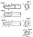
Fig 5 dargestellt entsteht bei dieser Ausbildung des Aussenkopfstückes 11 und des Innenkopfstückes 21 eine Schneidecke 222 die zur Schneidkante 121 des Aussenkopfstückes 11 leicht vorsteht. Mit dieser Schneidecke 222 kann der Chirurg sehr gezielt schneiden. Eine gängige Methode ist beispielsweise, dass er mittels seitlicher Schneidecke 222 eine grubenartige Vertiefung im abzutragenden Flächengewebe einschneidet. Im Monitor kann er auf diese Weise erkennen, wie viel Material er von der Fläche um die Furche herum bereits abgetragen hat. Dies ist eine grosse Hilfe als Referenzlinie zur Abschätzung des Materialabtrages während der Operation. Im Monitor können die relativen Grössenordnungen nur mit grosser Erfahrung und nur unpräzise erkannt werden. Diese Form des Chirurgischen Schneidinstrumentes ermöglicht deshalb schnelleres Arbeiten, ohne dass sich daraus ein grösseres Risiko ergibt. - Die grösste Neuerung, welche erst aufgrund neuer Herstellungstechniken und Wahl der richtigen Materialien möglich wurde, ist das Ausbilden des Innenkopfstückes mit ein, zwei oder drei Innenöffnungen 22 (
Fig. 12 ). Das zu lösende Problem war die Festigkeit des Materials des Innenkopfstückes. Dieses muss sehr zäh und trotzdem schweissbar sein. Ein Material das beide Eigenschaften aufweist wurde gefunden. Der grosse Vorteil den man mit zwei (Fig 13,14 ) oder gar drei (Fig 15 ) Innenöffnungen 22 hat, ergibt sich beim Absaugen von Spülflüssigkeit und Gewebe. Je besser die Schnittleistung und je grösser die Öffnung durch die man das abgetrennte Material abführen kann, desto sauberer ist das Arbeitsfeld und desto schneller und genauer kann der Chirurg arbeiten. - Das Aussenrohrkopfstück 11 bleibt bei,allen Formen der Innenrohrkopfstücke 21 immer gleich. Jede Innenöffnung, ob eine, zwei oder drei vorhanden sind, hat jeweils zwei Innenschneidkanten 221',221". Diese sind auch immer gleich ausgebildet, so dass mit dem Schneidinstrument mit einer Innenöffnung (
Fig 10,11,12 ), mit zwei Innenöffnungen (Fig 13,14 ) oder mit drei Innenöffnungen (Fig 15 ) in beiden Drehrichtungen gearbeitet werden kann. - Im praktischen Einsatz gibt sich die Notwendigkeit auch einen Fräskopf 223 (
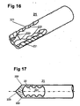
Fig. 17 ) einzusetzen. Um die Vorteile des oben beschriebenen chirurgischen Schneidwerkzeuges 1 zu nutzen und trotzdem ein Fräswerkzeug zur Verfügung zu haben, wurde an einem chirurgischen Schneidwerkzeug 1 der kegelige Abschluss des Innenkopfstückes 21 als Fräskopf 223 ausgebildet. Diese Anordnung hat zum Vorteil, dass das abgefräste Material sofort zur Innenöffnung 22 gelangt und dort abgesogen werden kann. Dieser Fräskopf 223 ist als "Kappe" mit mehreren Fräszähnen ausgebildet. Man erstrebt eine möglichst hohe Zahl an Fräszähnen. - Die Ausbildung des Fräskopfes 223 als Kappe zusammen mit der Tatsache, dass das vorgestellte chirurgische Schneidwerkzeug mit extrem kleinen Spielen arbeitet, hat den Vorteil, dass keine Weichteile um den Fräskopf 223 gewickelt werden. Dies ist eines der grossen Probleme die herkömmliche Fräswerkzeuge, vor allem wenn das Aussenkopfstück 11 so ausgebildet ist, dass der Fräskopf 223 nach vorne absolut frei ist, in diesem Einsatz oft haben. Der Aussenrohrkopfstück 11 bleibt auch für den Einsatz dieses mit Fräskopf 223 ausgestatteten Innenkopfstück 21 wie in
Fig 8 und Fig 9 dargestellt, immer gleich. - Versuche zeigten eindrücklich, dass bei gleicher Drehzahl des angetriebenen Innenrohres 20 eine weit grössere Schnittleistung erreicht werden kann. Ebenso wurde festgestellt, dass mit den erfindungsgemäss ausgestatteten Werkzeugen, insbesondere auch mit dem Innenkopfstück 21 mit Fräskopf 223
Fig 17 sehr viel weniger Kraft aufgewendet werden muss, als mit herkömmlichen Werkzeugen. Weitere durch den praktischen Einsatz erkennbare Vorteile sind: - Das vorgestellte Schneidinstrument ermöglicht schnelleres Arbeiten und ist dadurch nicht nur aus wirtschaftlichen Gründen den herkömmlichen Werkzeugen weit überlegen.
- Das vorgestellte Schneidinstrument kann als Klingen-Fräser (ohne Fräskopf 223 auf dem Innenkopfstück 21) und als Fräser-Klinge (mit dem Fräskopf 223 auf dem Innenkopfstück 21) eingesetzt werden. Die Einsatzbereiche überlappen sich derart, dass mit beiden Werkzeugen Bereiche bearbeitet werden können, die mehrere bekannte Werkzeuge und damit Werkzeugwechsel während der Operation ersetzen.
- Durch die gewählte Form der Schneidengeometrie ist die Verletzungsgefahr während des Einbringens des Werkzeuges in das Gewebe reduziert.
- Die runden Zähne sind um ein vielfaches robuster, als die spitzen Zähne der bekannten Werkzeuge.
- Die kegelige Ausbildung des Innenkopfstückes 21 erlaubt es, dasselbe als Bohrer einzusetzen.
- Die von den Rohren (Innenrohr 20 resp. Aussenrohr 10) getrennte Fertigung der Kopfstücke (Innenkopfstück 21 resp. Aussenkopfstück 11) erlaubt die Einhaltung von kleinen und immer gleichen Toleranzen, unabhängig vom Durchmesser des Werkzeuges.
Claims (9)
- Chirurgisches Schneidinstrument grosser Länge, bestehend aus einem Aussenrohr (10), welches im Endbereich (2) mit einem Aussenkopfstück (11) verbunden ist, das mindestens eine seitlich nach vorne gerichtete Aussenöffnung (12) mit mindestens zwei Aussenschneidkanten (121', 121") aufweist und einem Innenrohr (20), welches im Endbereich (2) mit einem Innenkopfstück (21) verbunden ist, das mindestens eine seitlich nach vorne gerichtete Innenöffnung (22) mit mindestens zwei über ihre Länge wellenförmig verlaufenden Innenschneidkanten (221', 221") aufweist, wobei das Innenrohr (20) im Aussenrohr (10) drehbar gelagert ist, und sich bei relativer Drehung des Innenrohres (20) im Aussenrohr (10) die Aussenschneidkanten (121', 121") und die Innenschneidkanten (221', 221") mit wenig Spiel aneinander vorbei bewegen, dadurch gekennzeichnet, dass die Aussenschneidkanten (121', 121") zur Tangente nach innen einen, spitzen Winkel α von 10 - 90° bilden und über die Länge wellenförmig mit aufstehenden runden Zähnen (224) und runden Zahnlücken (225) verlaufen und die Innenschneidkanten (221', 221") zur Tangente nach aussen einen spitzen Winkel β von 10 bis 90° bilden und ebenfalls wellenförmig mit aufstehenden runden Zähnen und runden Zahnlücken verlaufen.
- Schneidinstrument nach Anspruch 1, dadurch gekennzeichnet, dass das Aussenkopfstück (11) und das Innenkopfstück (21) im Endbereich eine kugelige Form zum Abschluss bilden.
- Schneidinstrument nach Anspruch 1, dadurch gekennzeichnet, dass das Aussenkopfstück (11) und das Innenkopfstück (21) im Endbereich eine kegelige Form zum Abschluss bilden.
- Schneidinstrument nach den Ansprüchen 1 und 2, dadurch gekennzeichnet, dass das Innenkopfstück (21) zwei Innenöffnungen (22', 22") mit jeweils zwei Innenschneidkanten (221', 221") aufweist.
- Schneidinstrument nach den Ansprüchen 1 und 3, dadurch gekennzeichnet, dass das Innenkopfstück (21) zwei Innenöffnungen (22', 22") mit jeweils zwei Innenschneidkanten (221', 221") aufweist.
- Schneidinstrument nach Anspruch 1 und 2, dadurch gekennzeichnet, dass das Innenkopfstück (21) drei Innenöffnungen (22', 22", 22"') mit jeweils zwei Innenschneidkanten (221', 221") aufweist.
- Schneidinstrument nach Anspruch 1 und 3, dadurch gekennzeichnet, dass das Innenkopfstück (21) drei Innenöffnungen (22', 22", 22"") mit jeweils zwei Innenschneidkanten (221', 221") aufweist.
- Schneidinstrument nach Ansprüchen 1 bis 7, dadurch gekennzeichnet, dass das Innenkopfstück (21) am Ende einen Fräskopf (223) aufweist.
- Schneidinstrument nach Anspruch 1, dadurch gekennzeichnet, dass die aufstehenden Zähne (224) mindesten doppelt so breit sind als die Zahnlücken (225).
Priority Applications (1)
| Application Number | Priority Date | Filing Date | Title |
|---|---|---|---|
| PL05772204T PL1773215T3 (pl) | 2004-07-22 | 2005-07-20 | Chirurgiczny instrument tnący |
Applications Claiming Priority (2)
| Application Number | Priority Date | Filing Date | Title |
|---|---|---|---|
| CH01243/04A CH700185B1 (de) | 2004-07-22 | 2004-07-22 | Chirurgisches Schneidinstrument. |
| PCT/IB2005/052425 WO2006011119A1 (de) | 2004-07-22 | 2005-07-20 | Chirurgisches schneidinstrument |
Publications (3)
| Publication Number | Publication Date |
|---|---|
| EP1773215A1 EP1773215A1 (de) | 2007-04-18 |
| EP1773215B1 EP1773215B1 (de) | 2010-12-15 |
| EP1773215B2 true EP1773215B2 (de) | 2019-07-24 |
Family
ID=35448134
Family Applications (1)
| Application Number | Title | Priority Date | Filing Date |
|---|---|---|---|
| EP05772204.3A Expired - Lifetime EP1773215B2 (de) | 2004-07-22 | 2005-07-20 | Chirurgisches schneidinstrument |
Country Status (12)
| Country | Link |
|---|---|
| US (1) | US20070282361A1 (de) |
| EP (1) | EP1773215B2 (de) |
| JP (1) | JP2008507314A (de) |
| CN (1) | CN100475167C (de) |
| AT (1) | ATE491399T1 (de) |
| AU (1) | AU2005265978A1 (de) |
| CH (1) | CH700185B1 (de) |
| DE (1) | DE502005010688D1 (de) |
| ES (1) | ES2356172T3 (de) |
| PL (1) | PL1773215T3 (de) |
| WO (1) | WO2006011119A1 (de) |
| ZA (1) | ZA200701307B (de) |
Families Citing this family (19)
| Publication number | Priority date | Publication date | Assignee | Title |
|---|---|---|---|---|
| US7666200B2 (en) * | 2006-07-19 | 2010-02-23 | Target Medical Innovations Llc | Endoscopic cutting instrument with axial and rotary motion |
| DE102006034756A1 (de) | 2006-07-24 | 2008-01-31 | Karl Storz Gmbh & Co. Kg | Medizinisches Instrument zum Schneiden von Gewebe |
| US20080208194A1 (en) * | 2007-02-13 | 2008-08-28 | Christine Bickenbach | Double cut shaver |
| US9050123B2 (en) | 2007-04-16 | 2015-06-09 | Smith & Nephew, Inc. | Powered surgical system |
| US8409235B2 (en) * | 2010-04-30 | 2013-04-02 | Medtronic Xomed, Inc. | Rotary cutting tool with improved cutting and reduced clogging on soft tissue and thin bone |
| CH703836B1 (de) | 2010-09-29 | 2014-09-30 | Orlando Da Rold | Kupplungsteil einer chirurgischen Vorrichtung zum Kuppeln mit einem chirurgischen Handstück. |
| US8574254B2 (en) | 2011-01-25 | 2013-11-05 | Smith & Nephew, Inc. | Arthroscopic cutting blade |
| US9358036B2 (en) * | 2013-03-12 | 2016-06-07 | Gyrus Acmi, Inc. | Blade positioning device |
| US20150223831A1 (en) * | 2014-02-12 | 2015-08-13 | Arthrex, Inc. | Surgical shaver assembly |
| US10667836B2 (en) * | 2014-04-28 | 2020-06-02 | Boston Scientific Scimed, Inc. | Tissue resectors, hand operated tissue resecting systems, and associated methods |
| BR112017004321B1 (pt) * | 2014-09-05 | 2022-04-19 | Ethicon Llc | Instrumento cirúrgico |
| US9737322B2 (en) | 2014-09-08 | 2017-08-22 | Medtronic Xomed, Inc. | Method for resection of tumors and tissues |
| US9636132B2 (en) * | 2014-09-08 | 2017-05-02 | Medtronic Xomed, Inc. | Tumor debulker |
| WO2019028221A1 (en) | 2017-08-02 | 2019-02-07 | Stryker Corporation | SURGICAL TOOL SYSTEMS AND METHODS OF USE |
| CN109717924A (zh) * | 2019-01-31 | 2019-05-07 | 重庆市第四人民医院 | 黄韧带刨削刀 |
| CN113576626A (zh) * | 2021-07-21 | 2021-11-02 | 英姿医疗科技(苏州)有限公司 | 一种刀管组件、刨削器和刨削系统 |
| CN114129221B (zh) * | 2021-11-19 | 2024-07-26 | 江苏金泰医疗器械有限公司 | 一种除栓装置 |
| CH719484A1 (de) | 2022-03-08 | 2023-09-15 | Swiss Medical Instr Ag | Verfahren zur Herstellung eines Innenrohrs für ein chirurgisches Schneidinstrument. |
| WO2025057140A1 (de) | 2023-09-14 | 2025-03-20 | Swiss Medical Instruments Ag | Innenrohr für ein chirurgisches schneidinstrument und verfahren zu dessen herstellung |
Citations (9)
| Publication number | Priority date | Publication date | Assignee | Title |
|---|---|---|---|---|
| US4811734A (en) † | 1987-08-13 | 1989-03-14 | Baxter Travenol Laboratories, Inc. | Surgical cutting instrument |
| US5601583A (en) † | 1995-02-15 | 1997-02-11 | Smith & Nephew Endoscopy Inc. | Surgical instrument |
| US5643303A (en) † | 1993-01-26 | 1997-07-01 | Donahue; John R. | Flexible surgical instrument |
| US5709698A (en) † | 1996-02-26 | 1998-01-20 | Linvatec Corporation | Irrigating/aspirating shaver blade assembly |
| US5766199A (en) † | 1996-04-10 | 1998-06-16 | Linvatec Corporation | Endoscopic shaver blade with resilient cutting edges |
| US6053928A (en) † | 1996-04-10 | 2000-04-25 | Linvatec Corporation | Process for shaping and sharpening a rotatable surgical shaver blade |
| US6419684B1 (en) † | 2000-05-16 | 2002-07-16 | Linvatec Corporation | End-cutting shaver blade for axial resection |
| US6428539B1 (en) † | 2000-03-09 | 2002-08-06 | Origin Medsystems, Inc. | Apparatus and method for minimally invasive surgery using rotational cutting tool |
| US6620180B1 (en) † | 1998-09-09 | 2003-09-16 | Medtronic Xomed, Inc. | Powered laryngeal cutting blade |
Family Cites Families (11)
| Publication number | Priority date | Publication date | Assignee | Title |
|---|---|---|---|---|
| US4203444A (en) * | 1977-11-07 | 1980-05-20 | Dyonics, Inc. | Surgical instrument suitable for closed surgery such as of the knee |
| US4850354A (en) * | 1987-08-13 | 1989-07-25 | Baxter Travenol Laboratories, Inc. | Surgical cutting instrument |
| JPH01159824A (ja) * | 1987-12-16 | 1989-06-22 | Toyobo Co Ltd | 磁気記録媒体 |
| US6770074B2 (en) * | 1988-06-13 | 2004-08-03 | Gary Karlin Michelson | Apparatus for use in inserting spinal implants |
| US5217479A (en) * | 1991-02-14 | 1993-06-08 | Linvatec Corporation | Surgical cutting instrument |
| US5269798A (en) | 1992-02-19 | 1993-12-14 | Linvatec Corporation | Surgical cutting instrument with movable, inner and outer tubular members |
| DE4422426C2 (de) * | 1994-06-28 | 1998-02-26 | Kurt Eberle Kg | Chirurgisches Instrument zum Entfernen von Gewebe oder Knorpel |
| AU722939B2 (en) * | 1996-04-10 | 2000-08-17 | Linvatec Corporation | Process for shaping and sharpening a rotatable surgical shaver blade |
| US5913867A (en) * | 1996-12-23 | 1999-06-22 | Smith & Nephew, Inc. | Surgical instrument |
| US6217598B1 (en) * | 1997-11-25 | 2001-04-17 | Linvatec Corporation | End-cutting shaver blade |
| US6053923A (en) * | 1998-03-17 | 2000-04-25 | Arthrotek, Inc. | Method and apparatus for abrading tissue |
-
2004
- 2004-07-22 CH CH01243/04A patent/CH700185B1/de not_active IP Right Cessation
-
2005
- 2005-07-20 JP JP2007522106A patent/JP2008507314A/ja active Pending
- 2005-07-20 AT AT05772204T patent/ATE491399T1/de active
- 2005-07-20 AU AU2005265978A patent/AU2005265978A1/en not_active Abandoned
- 2005-07-20 ES ES05772204T patent/ES2356172T3/es not_active Expired - Lifetime
- 2005-07-20 WO PCT/IB2005/052425 patent/WO2006011119A1/de not_active Ceased
- 2005-07-20 EP EP05772204.3A patent/EP1773215B2/de not_active Expired - Lifetime
- 2005-07-20 PL PL05772204T patent/PL1773215T3/pl unknown
- 2005-07-20 DE DE502005010688T patent/DE502005010688D1/de not_active Expired - Lifetime
- 2005-07-20 CN CNB200580024218XA patent/CN100475167C/zh not_active Expired - Fee Related
- 2005-07-20 US US11/632,858 patent/US20070282361A1/en not_active Abandoned
-
2007
- 2007-02-14 ZA ZA200701307A patent/ZA200701307B/en unknown
Patent Citations (9)
| Publication number | Priority date | Publication date | Assignee | Title |
|---|---|---|---|---|
| US4811734A (en) † | 1987-08-13 | 1989-03-14 | Baxter Travenol Laboratories, Inc. | Surgical cutting instrument |
| US5643303A (en) † | 1993-01-26 | 1997-07-01 | Donahue; John R. | Flexible surgical instrument |
| US5601583A (en) † | 1995-02-15 | 1997-02-11 | Smith & Nephew Endoscopy Inc. | Surgical instrument |
| US5709698A (en) † | 1996-02-26 | 1998-01-20 | Linvatec Corporation | Irrigating/aspirating shaver blade assembly |
| US5766199A (en) † | 1996-04-10 | 1998-06-16 | Linvatec Corporation | Endoscopic shaver blade with resilient cutting edges |
| US6053928A (en) † | 1996-04-10 | 2000-04-25 | Linvatec Corporation | Process for shaping and sharpening a rotatable surgical shaver blade |
| US6620180B1 (en) † | 1998-09-09 | 2003-09-16 | Medtronic Xomed, Inc. | Powered laryngeal cutting blade |
| US6428539B1 (en) † | 2000-03-09 | 2002-08-06 | Origin Medsystems, Inc. | Apparatus and method for minimally invasive surgery using rotational cutting tool |
| US6419684B1 (en) † | 2000-05-16 | 2002-07-16 | Linvatec Corporation | End-cutting shaver blade for axial resection |
Also Published As
| Publication number | Publication date |
|---|---|
| CN100475167C (zh) | 2009-04-08 |
| US20070282361A1 (en) | 2007-12-06 |
| CN101001578A (zh) | 2007-07-18 |
| ZA200701307B (en) | 2008-07-30 |
| ES2356172T3 (es) | 2011-04-05 |
| AU2005265978A1 (en) | 2006-02-02 |
| EP1773215B1 (de) | 2010-12-15 |
| EP1773215A1 (de) | 2007-04-18 |
| ATE491399T1 (de) | 2011-01-15 |
| JP2008507314A (ja) | 2008-03-13 |
| WO2006011119A1 (de) | 2006-02-02 |
| CH700185B1 (de) | 2010-07-15 |
| PL1773215T3 (pl) | 2011-05-31 |
| DE502005010688D1 (de) | 2011-01-27 |
Similar Documents
| Publication | Publication Date | Title |
|---|---|---|
| EP1773215B1 (de) | Chirurgisches schneidinstrument | |
| EP2096982B1 (de) | Vorrichtung und verfahren zum minimal-invasiven eingriff an der wirbelsäule | |
| DE69019381T2 (de) | Dünne Stützplatte für Zange. | |
| DE69731786T2 (de) | Endoskopische Schaberklinge mit federnden Schneidkanten | |
| DE102007036943B4 (de) | Fußchirurgie-Knochenplatte | |
| EP2521518B1 (de) | Vorrichtung zum schneiden und absaugen von gewebe | |
| DE19634484C1 (de) | Knochenfräser | |
| DE3688207T2 (de) | Chirurgische Instrumente. | |
| DE2848314C2 (de) | Chirurgisches Instrument | |
| DE69632247T2 (de) | Vorrichtung zur wiederherstellung von gelenkknorpeldefekten | |
| DE102012200666B4 (de) | Sonotrode, chirurgisches Instrument mit einer Sonotrode sowie Herstellungsverfahren für eine Sonotrode | |
| DE69814938T2 (de) | Knochenschraube zum Verbinden von Knochenteilchen | |
| EP2497432B1 (de) | Medizinisches Einstechwerkzeug | |
| DE202011111061U1 (de) | Orthopädische Fräsvorrichtung zur Knochenpräparation, insbesondere Gelenkpräparation | |
| WO2014146797A1 (de) | Instrumentenset und verfahren zum einbringen eines körbchens in das bandscheibenfach zwischen zwei wirbelkörpern | |
| EP3402418B1 (de) | Medizinisches raspelinstrument | |
| EP2964112B1 (de) | Medizinisches werkzeugsystem | |
| DE3321091A1 (de) | Verfahren und vorrichtung zum einbringen oder erweitern von loechern in kunststoffbehaeltern | |
| EP2563243B1 (de) | Knochenbiopsiefräser | |
| CH719484A1 (de) | Verfahren zur Herstellung eines Innenrohrs für ein chirurgisches Schneidinstrument. | |
| WO2005023122A1 (de) | Medizinisches instrument zum präparieren von gewebe | |
| DE102008050804B4 (de) | Modulare Hohlraspel | |
| DE102007002855A1 (de) | Probenahmevorrichtung, insbesondere Biopsienadel | |
| DE102004028429B3 (de) | Vorrichtung zum Ausstanzen von Gewebebereichen an Knochen | |
| EP4057919B1 (de) | Chirurgischer fräser mit verbesserter spanabfuhr |
Legal Events
| Date | Code | Title | Description |
|---|---|---|---|
| PUAI | Public reference made under article 153(3) epc to a published international application that has entered the european phase |
Free format text: ORIGINAL CODE: 0009012 |
|
| AK | Designated contracting states |
Kind code of ref document: A1 Designated state(s): AT BE BG CH CY CZ DE DK EE ES FI FR GB GR HU IE IS IT LI LT LU LV MC NL PL PT RO SE SI SK TR |
|
| 17P | Request for examination filed |
Effective date: 20070222 |
|
| DAX | Request for extension of the european patent (deleted) | ||
| GRAP | Despatch of communication of intention to grant a patent |
Free format text: ORIGINAL CODE: EPIDOSNIGR1 |
|
| GRAS | Grant fee paid |
Free format text: ORIGINAL CODE: EPIDOSNIGR3 |
|
| GRAA | (expected) grant |
Free format text: ORIGINAL CODE: 0009210 |
|
| AK | Designated contracting states |
Kind code of ref document: B1 Designated state(s): AT BE BG CH CY CZ DE DK EE ES FI FR GB GR HU IE IS IT LI LT LU LV MC NL PL PT RO SE SI SK TR |
|
| REG | Reference to a national code |
Ref country code: CH Ref legal event code: EP Ref country code: GB Ref legal event code: FG4D Free format text: NOT ENGLISH |
|
| REG | Reference to a national code |
Ref country code: CH Ref legal event code: NV Representative=s name: INDUSTRIEBERATUNG MAIER AG |
|
| REG | Reference to a national code |
Ref country code: IE Ref legal event code: FG4D |
|
| REF | Corresponds to: |
Ref document number: 502005010688 Country of ref document: DE Date of ref document: 20110127 Kind code of ref document: P |
|
| REG | Reference to a national code |
Ref country code: DE Ref legal event code: R096 Ref document number: 502005010688 Country of ref document: DE Effective date: 20110127 |
|
| REG | Reference to a national code |
Ref country code: SE Ref legal event code: TRGR |
|
| REG | Reference to a national code |
Ref country code: NL Ref legal event code: T3 |
|
| REG | Reference to a national code |
Ref country code: ES Ref legal event code: FG2A Ref document number: 2356172 Country of ref document: ES Kind code of ref document: T3 Effective date: 20110405 |
|
| PG25 | Lapsed in a contracting state [announced via postgrant information from national office to epo] |
Ref country code: LT Free format text: LAPSE BECAUSE OF FAILURE TO SUBMIT A TRANSLATION OF THE DESCRIPTION OR TO PAY THE FEE WITHIN THE PRESCRIBED TIME-LIMIT Effective date: 20101215 |
|
| LTIE | Lt: invalidation of european patent or patent extension |
Effective date: 20101215 |
|
| PG25 | Lapsed in a contracting state [announced via postgrant information from national office to epo] |
Ref country code: SI Free format text: LAPSE BECAUSE OF FAILURE TO SUBMIT A TRANSLATION OF THE DESCRIPTION OR TO PAY THE FEE WITHIN THE PRESCRIBED TIME-LIMIT Effective date: 20101215 Ref country code: LV Free format text: LAPSE BECAUSE OF FAILURE TO SUBMIT A TRANSLATION OF THE DESCRIPTION OR TO PAY THE FEE WITHIN THE PRESCRIBED TIME-LIMIT Effective date: 20101215 Ref country code: BG Free format text: LAPSE BECAUSE OF FAILURE TO SUBMIT A TRANSLATION OF THE DESCRIPTION OR TO PAY THE FEE WITHIN THE PRESCRIBED TIME-LIMIT Effective date: 20110315 Ref country code: FI Free format text: LAPSE BECAUSE OF FAILURE TO SUBMIT A TRANSLATION OF THE DESCRIPTION OR TO PAY THE FEE WITHIN THE PRESCRIBED TIME-LIMIT Effective date: 20101215 Ref country code: CY Free format text: LAPSE BECAUSE OF FAILURE TO SUBMIT A TRANSLATION OF THE DESCRIPTION OR TO PAY THE FEE WITHIN THE PRESCRIBED TIME-LIMIT Effective date: 20101215 |
|
| REG | Reference to a national code |
Ref country code: PL Ref legal event code: T3 |
|
| REG | Reference to a national code |
Ref country code: IE Ref legal event code: FD4D |
|
| PG25 | Lapsed in a contracting state [announced via postgrant information from national office to epo] |
Ref country code: IS Free format text: LAPSE BECAUSE OF FAILURE TO SUBMIT A TRANSLATION OF THE DESCRIPTION OR TO PAY THE FEE WITHIN THE PRESCRIBED TIME-LIMIT Effective date: 20110415 Ref country code: GR Free format text: LAPSE BECAUSE OF FAILURE TO SUBMIT A TRANSLATION OF THE DESCRIPTION OR TO PAY THE FEE WITHIN THE PRESCRIBED TIME-LIMIT Effective date: 20110316 Ref country code: EE Free format text: LAPSE BECAUSE OF FAILURE TO SUBMIT A TRANSLATION OF THE DESCRIPTION OR TO PAY THE FEE WITHIN THE PRESCRIBED TIME-LIMIT Effective date: 20101215 Ref country code: PT Free format text: LAPSE BECAUSE OF FAILURE TO SUBMIT A TRANSLATION OF THE DESCRIPTION OR TO PAY THE FEE WITHIN THE PRESCRIBED TIME-LIMIT Effective date: 20110415 Ref country code: IE Free format text: LAPSE BECAUSE OF FAILURE TO SUBMIT A TRANSLATION OF THE DESCRIPTION OR TO PAY THE FEE WITHIN THE PRESCRIBED TIME-LIMIT Effective date: 20101215 Ref country code: CZ Free format text: LAPSE BECAUSE OF FAILURE TO SUBMIT A TRANSLATION OF THE DESCRIPTION OR TO PAY THE FEE WITHIN THE PRESCRIBED TIME-LIMIT Effective date: 20101215 |
|
| PG25 | Lapsed in a contracting state [announced via postgrant information from national office to epo] |
Ref country code: SK Free format text: LAPSE BECAUSE OF FAILURE TO SUBMIT A TRANSLATION OF THE DESCRIPTION OR TO PAY THE FEE WITHIN THE PRESCRIBED TIME-LIMIT Effective date: 20101215 Ref country code: RO Free format text: LAPSE BECAUSE OF FAILURE TO SUBMIT A TRANSLATION OF THE DESCRIPTION OR TO PAY THE FEE WITHIN THE PRESCRIBED TIME-LIMIT Effective date: 20101215 |
|
| PLBI | Opposition filed |
Free format text: ORIGINAL CODE: 0009260 |
|
| PLAX | Notice of opposition and request to file observation + time limit sent |
Free format text: ORIGINAL CODE: EPIDOSNOBS2 |
|
| 26 | Opposition filed |
Opponent name: SCHMITT-NILSON, DR. GERT Effective date: 20110915 |
|
| PG25 | Lapsed in a contracting state [announced via postgrant information from national office to epo] |
Ref country code: DK Free format text: LAPSE BECAUSE OF FAILURE TO SUBMIT A TRANSLATION OF THE DESCRIPTION OR TO PAY THE FEE WITHIN THE PRESCRIBED TIME-LIMIT Effective date: 20101215 |
|
| REG | Reference to a national code |
Ref country code: DE Ref legal event code: R026 Ref document number: 502005010688 Country of ref document: DE Effective date: 20110915 |
|
| PLBB | Reply of patent proprietor to notice(s) of opposition received |
Free format text: ORIGINAL CODE: EPIDOSNOBS3 |
|
| PG25 | Lapsed in a contracting state [announced via postgrant information from national office to epo] |
Ref country code: MC Free format text: LAPSE BECAUSE OF NON-PAYMENT OF DUE FEES Effective date: 20110731 |
|
| PGFP | Annual fee paid to national office [announced via postgrant information from national office to epo] |
Ref country code: PL Payment date: 20120426 Year of fee payment: 8 |
|
| PGFP | Annual fee paid to national office [announced via postgrant information from national office to epo] |
Ref country code: ES Payment date: 20120720 Year of fee payment: 8 |
|
| PG25 | Lapsed in a contracting state [announced via postgrant information from national office to epo] |
Ref country code: LU Free format text: LAPSE BECAUSE OF NON-PAYMENT OF DUE FEES Effective date: 20110720 |
|
| APBM | Appeal reference recorded |
Free format text: ORIGINAL CODE: EPIDOSNREFNO |
|
| APBP | Date of receipt of notice of appeal recorded |
Free format text: ORIGINAL CODE: EPIDOSNNOA2O |
|
| APAH | Appeal reference modified |
Free format text: ORIGINAL CODE: EPIDOSCREFNO |
|
| PG25 | Lapsed in a contracting state [announced via postgrant information from national office to epo] |
Ref country code: TR Free format text: LAPSE BECAUSE OF FAILURE TO SUBMIT A TRANSLATION OF THE DESCRIPTION OR TO PAY THE FEE WITHIN THE PRESCRIBED TIME-LIMIT Effective date: 20101215 |
|
| PGFP | Annual fee paid to national office [announced via postgrant information from national office to epo] |
Ref country code: BE Payment date: 20130621 Year of fee payment: 9 |
|
| APBQ | Date of receipt of statement of grounds of appeal recorded |
Free format text: ORIGINAL CODE: EPIDOSNNOA3O |
|
| PG25 | Lapsed in a contracting state [announced via postgrant information from national office to epo] |
Ref country code: HU Free format text: LAPSE BECAUSE OF FAILURE TO SUBMIT A TRANSLATION OF THE DESCRIPTION OR TO PAY THE FEE WITHIN THE PRESCRIBED TIME-LIMIT Effective date: 20101215 |
|
| PGFP | Annual fee paid to national office [announced via postgrant information from national office to epo] |
Ref country code: NL Payment date: 20130710 Year of fee payment: 9 Ref country code: SE Payment date: 20130709 Year of fee payment: 9 Ref country code: AT Payment date: 20130710 Year of fee payment: 9 |
|
| PGFP | Annual fee paid to national office [announced via postgrant information from national office to epo] |
Ref country code: GB Payment date: 20130709 Year of fee payment: 9 |
|
| PGFP | Annual fee paid to national office [announced via postgrant information from national office to epo] |
Ref country code: IT Payment date: 20130726 Year of fee payment: 9 |
|
| REG | Reference to a national code |
Ref country code: PL Ref legal event code: LAPE |
|
| PG25 | Lapsed in a contracting state [announced via postgrant information from national office to epo] |
Ref country code: PL Free format text: LAPSE BECAUSE OF NON-PAYMENT OF DUE FEES Effective date: 20130720 |
|
| REG | Reference to a national code |
Ref country code: NL Ref legal event code: V1 Effective date: 20150201 |
|
| REG | Reference to a national code |
Ref country code: SE Ref legal event code: EUG |
|
| REG | Reference to a national code |
Ref country code: AT Ref legal event code: MM01 Ref document number: 491399 Country of ref document: AT Kind code of ref document: T Effective date: 20140720 |
|
| GBPC | Gb: european patent ceased through non-payment of renewal fee |
Effective date: 20140720 |
|
| PG25 | Lapsed in a contracting state [announced via postgrant information from national office to epo] |
Ref country code: NL Free format text: LAPSE BECAUSE OF NON-PAYMENT OF DUE FEES Effective date: 20150201 |
|
| PG25 | Lapsed in a contracting state [announced via postgrant information from national office to epo] |
Ref country code: IT Free format text: LAPSE BECAUSE OF NON-PAYMENT OF DUE FEES Effective date: 20140720 |
|
| PG25 | Lapsed in a contracting state [announced via postgrant information from national office to epo] |
Ref country code: SE Free format text: LAPSE BECAUSE OF NON-PAYMENT OF DUE FEES Effective date: 20140721 Ref country code: GB Free format text: LAPSE BECAUSE OF NON-PAYMENT OF DUE FEES Effective date: 20140720 Ref country code: AT Free format text: LAPSE BECAUSE OF NON-PAYMENT OF DUE FEES Effective date: 20140720 |
|
| REG | Reference to a national code |
Ref country code: ES Ref legal event code: FD2A Effective date: 20150828 |
|
| PG25 | Lapsed in a contracting state [announced via postgrant information from national office to epo] |
Ref country code: ES Free format text: LAPSE BECAUSE OF NON-PAYMENT OF DUE FEES Effective date: 20140721 |
|
| REG | Reference to a national code |
Ref country code: CH Ref legal event code: PUE Owner name: DA ROLD ENGINEERING AG, CH Free format text: FORMER OWNER: DA ROLD, ORLANDO, CH |
|
| REG | Reference to a national code |
Ref country code: FR Ref legal event code: ST Effective date: 20160331 |
|
| PG25 | Lapsed in a contracting state [announced via postgrant information from national office to epo] |
Ref country code: FR Free format text: LAPSE BECAUSE OF NON-PAYMENT OF DUE FEES Effective date: 20150731 |
|
| REG | Reference to a national code |
Ref country code: FR Ref legal event code: TP Owner name: DA ROLD ENGINEERING AG, CH Effective date: 20160509 |
|
| REG | Reference to a national code |
Ref country code: FR Ref legal event code: PLFP Year of fee payment: 12 |
|
| RAP2 | Party data changed (patent owner data changed or rights of a patent transferred) |
Owner name: DA ROLD ENGINEERING AG |
|
| REG | Reference to a national code |
Ref country code: FR Ref legal event code: RN Effective date: 20160830 Ref country code: FR Ref legal event code: FC Effective date: 20160901 |
|
| REG | Reference to a national code |
Ref country code: CH Ref legal event code: PCOW Free format text: NEW ADDRESS: BEI ROTH HOLDING AG ROAMERSTRASSE 4, 4500 SOLOTHURN (CH) |
|
| REG | Reference to a national code |
Ref country code: DE Ref legal event code: R082 Ref document number: 502005010688 Country of ref document: DE Representative=s name: PATENTANWAELTE JECK, FLECK & PARTNER MBB, DE Ref country code: DE Ref legal event code: R081 Ref document number: 502005010688 Country of ref document: DE Owner name: DA ROLD ENGINEERING AG, CH Free format text: FORMER OWNER: DA ROLD, ORLANDO, SOLOTHURN, CH Ref country code: DE Ref legal event code: R082 Ref document number: 502005010688 Country of ref document: DE Representative=s name: JECK - FLECK - HERRMANN PATENTANWAELTE, DE Ref country code: DE Ref legal event code: R082 Ref document number: 502005010688 Country of ref document: DE Representative=s name: JECK - FLECK PATENTANWAELTE, DE |
|
| RAP2 | Party data changed (patent owner data changed or rights of a patent transferred) |
Owner name: DA ROLD ENGINEERING AG |
|
| PG25 | Lapsed in a contracting state [announced via postgrant information from national office to epo] |
Ref country code: FR Free format text: LAPSE BECAUSE OF NON-PAYMENT OF DUE FEES Effective date: 20150731 |
|
| PGRI | Patent reinstated in contracting state [announced from national office to epo] |
Ref country code: FR Effective date: 20160901 |
|
| REG | Reference to a national code |
Ref country code: FR Ref legal event code: CA Effective date: 20170407 |
|
| PLAB | Opposition data, opponent's data or that of the opponent's representative modified |
Free format text: ORIGINAL CODE: 0009299OPPO |
|
| R26 | Opposition filed (corrected) |
Opponent name: SCHMITT-NILSON, DR. GERT Effective date: 20110915 |
|
| REG | Reference to a national code |
Ref country code: FR Ref legal event code: PLFP Year of fee payment: 13 |
|
| PG25 | Lapsed in a contracting state [announced via postgrant information from national office to epo] |
Ref country code: BE Free format text: LAPSE BECAUSE OF NON-PAYMENT OF DUE FEES Effective date: 20140731 |
|
| REG | Reference to a national code |
Ref country code: CH Ref legal event code: PFA Owner name: DA ROLD ENGINEERING AG, CH Free format text: FORMER OWNER: DA ROLD ENGINEERING AG, CH |
|
| REG | Reference to a national code |
Ref country code: FR Ref legal event code: PLFP Year of fee payment: 14 |
|
| APBU | Appeal procedure closed |
Free format text: ORIGINAL CODE: EPIDOSNNOA9O |
|
| PUAH | Patent maintained in amended form |
Free format text: ORIGINAL CODE: 0009272 |
|
| STAA | Information on the status of an ep patent application or granted ep patent |
Free format text: STATUS: PATENT MAINTAINED AS AMENDED |
|
| REG | Reference to a national code |
Ref country code: CH Ref legal event code: AELC |
|
| 27A | Patent maintained in amended form |
Effective date: 20190724 |
|
| AK | Designated contracting states |
Kind code of ref document: B2 Designated state(s): AT BE BG CH CY CZ DE DK EE ES FI FR GB GR HU IE IS IT LI LT LU LV MC NL PL PT RO SE SI SK TR |
|
| REG | Reference to a national code |
Ref country code: DE Ref legal event code: R102 Ref document number: 502005010688 Country of ref document: DE |
|
| REG | Reference to a national code |
Ref country code: CH Ref legal event code: PCAR Free format text: NEW ADDRESS: BERGLIHOEH 3, 8725 ERNETSCHWIL (CH) |
|
| PGFP | Annual fee paid to national office [announced via postgrant information from national office to epo] |
Ref country code: DE Payment date: 20240610 Year of fee payment: 20 |
|
| PGFP | Annual fee paid to national office [announced via postgrant information from national office to epo] |
Ref country code: FR Payment date: 20240708 Year of fee payment: 20 |
|
| PGFP | Annual fee paid to national office [announced via postgrant information from national office to epo] |
Ref country code: CH Payment date: 20240924 Year of fee payment: 20 |
|
| REG | Reference to a national code |
Ref country code: DE Ref legal event code: R071 Ref document number: 502005010688 Country of ref document: DE |
|
| REG | Reference to a national code |
Ref country code: CH Ref legal event code: PL |