EP1774162B1 - Procede et dispositif de commande d'un moteur a combustion interne - Google Patents
Procede et dispositif de commande d'un moteur a combustion interne Download PDFInfo
- Publication number
- EP1774162B1 EP1774162B1 EP05777714A EP05777714A EP1774162B1 EP 1774162 B1 EP1774162 B1 EP 1774162B1 EP 05777714 A EP05777714 A EP 05777714A EP 05777714 A EP05777714 A EP 05777714A EP 1774162 B1 EP1774162 B1 EP 1774162B1
- Authority
- EP
- European Patent Office
- Prior art keywords
- pressure
- combustion chamber
- gas
- cylinder
- temperature
- Prior art date
- Legal status (The legal status is an assumption and is not a legal conclusion. Google has not performed a legal analysis and makes no representation as to the accuracy of the status listed.)
- Expired - Lifetime
Links
Images

Classifications
-
- F—MECHANICAL ENGINEERING; LIGHTING; HEATING; WEAPONS; BLASTING
- F02—COMBUSTION ENGINES; HOT-GAS OR COMBUSTION-PRODUCT ENGINE PLANTS
- F02D—CONTROLLING COMBUSTION ENGINES
- F02D35/00—Controlling engines, dependent on conditions exterior or interior to engines, not otherwise provided for
- F02D35/02—Controlling engines, dependent on conditions exterior or interior to engines, not otherwise provided for on interior conditions
- F02D35/025—Controlling engines, dependent on conditions exterior or interior to engines, not otherwise provided for on interior conditions by determining temperatures inside the cylinder, e.g. combustion temperatures
- F02D35/026—Controlling engines, dependent on conditions exterior or interior to engines, not otherwise provided for on interior conditions by determining temperatures inside the cylinder, e.g. combustion temperatures using an estimation
-
- F—MECHANICAL ENGINEERING; LIGHTING; HEATING; WEAPONS; BLASTING
- F02—COMBUSTION ENGINES; HOT-GAS OR COMBUSTION-PRODUCT ENGINE PLANTS
- F02B—INTERNAL-COMBUSTION PISTON ENGINES; COMBUSTION ENGINES IN GENERAL
- F02B77/00—Component parts, details or accessories, not otherwise provided for
- F02B77/08—Safety, indicating, or supervising devices
- F02B77/085—Safety, indicating, or supervising devices with sensors measuring combustion processes, e.g. knocking, pressure, ionization, combustion flame
- F02B77/086—Sensor arrangements in the exhaust, e.g. for temperature, misfire, air/fuel ratio, oxygen sensors
-
- F—MECHANICAL ENGINEERING; LIGHTING; HEATING; WEAPONS; BLASTING
- F02—COMBUSTION ENGINES; HOT-GAS OR COMBUSTION-PRODUCT ENGINE PLANTS
- F02B—INTERNAL-COMBUSTION PISTON ENGINES; COMBUSTION ENGINES IN GENERAL
- F02B77/00—Component parts, details or accessories, not otherwise provided for
- F02B77/08—Safety, indicating, or supervising devices
- F02B77/089—Safety, indicating, or supervising devices relating to engine temperature
-
- F—MECHANICAL ENGINEERING; LIGHTING; HEATING; WEAPONS; BLASTING
- F02—COMBUSTION ENGINES; HOT-GAS OR COMBUSTION-PRODUCT ENGINE PLANTS
- F02D—CONTROLLING COMBUSTION ENGINES
- F02D35/00—Controlling engines, dependent on conditions exterior or interior to engines, not otherwise provided for
- F02D35/02—Controlling engines, dependent on conditions exterior or interior to engines, not otherwise provided for on interior conditions
- F02D35/023—Controlling engines, dependent on conditions exterior or interior to engines, not otherwise provided for on interior conditions by determining the cylinder pressure
-
- F—MECHANICAL ENGINEERING; LIGHTING; HEATING; WEAPONS; BLASTING
- F02—COMBUSTION ENGINES; HOT-GAS OR COMBUSTION-PRODUCT ENGINE PLANTS
- F02D—CONTROLLING COMBUSTION ENGINES
- F02D41/00—Electrical control of supply of combustible mixture or its constituents
- F02D41/02—Circuit arrangements for generating control signals
- F02D41/14—Introducing closed-loop corrections
- F02D41/1438—Introducing closed-loop corrections using means for determining characteristics of the combustion gases; Sensors therefor
- F02D41/1444—Introducing closed-loop corrections using means for determining characteristics of the combustion gases; Sensors therefor characterised by the characteristics of the combustion gases
- F02D41/1446—Introducing closed-loop corrections using means for determining characteristics of the combustion gases; Sensors therefor characterised by the characteristics of the combustion gases the characteristics being exhaust temperatures
- F02D41/1447—Introducing closed-loop corrections using means for determining characteristics of the combustion gases; Sensors therefor characterised by the characteristics of the combustion gases the characteristics being exhaust temperatures with determination means using an estimation
-
- F—MECHANICAL ENGINEERING; LIGHTING; HEATING; WEAPONS; BLASTING
- F02—COMBUSTION ENGINES; HOT-GAS OR COMBUSTION-PRODUCT ENGINE PLANTS
- F02D—CONTROLLING COMBUSTION ENGINES
- F02D41/00—Electrical control of supply of combustible mixture or its constituents
- F02D41/30—Controlling fuel injection
- F02D41/3011—Controlling fuel injection according to or using specific or several modes of combustion
- F02D41/3017—Controlling fuel injection according to or using specific or several modes of combustion characterised by the mode(s) being used
- F02D41/3035—Controlling fuel injection according to or using specific or several modes of combustion characterised by the mode(s) being used a mode being the premixed charge compression-ignition mode
-
- F—MECHANICAL ENGINEERING; LIGHTING; HEATING; WEAPONS; BLASTING
- F02—COMBUSTION ENGINES; HOT-GAS OR COMBUSTION-PRODUCT ENGINE PLANTS
- F02D—CONTROLLING COMBUSTION ENGINES
- F02D41/00—Electrical control of supply of combustible mixture or its constituents
- F02D41/30—Controlling fuel injection
- F02D41/38—Controlling fuel injection of the high pressure type
- F02D41/40—Controlling fuel injection of the high pressure type with means for controlling injection timing or duration
- F02D41/402—Multiple injections
-
- F—MECHANICAL ENGINEERING; LIGHTING; HEATING; WEAPONS; BLASTING
- F02—COMBUSTION ENGINES; HOT-GAS OR COMBUSTION-PRODUCT ENGINE PLANTS
- F02B—INTERNAL-COMBUSTION PISTON ENGINES; COMBUSTION ENGINES IN GENERAL
- F02B1/00—Engines characterised by fuel-air mixture compression
- F02B1/12—Engines characterised by fuel-air mixture compression with compression ignition
-
- F—MECHANICAL ENGINEERING; LIGHTING; HEATING; WEAPONS; BLASTING
- F02—COMBUSTION ENGINES; HOT-GAS OR COMBUSTION-PRODUCT ENGINE PLANTS
- F02D—CONTROLLING COMBUSTION ENGINES
- F02D41/00—Electrical control of supply of combustible mixture or its constituents
- F02D41/0025—Controlling engines characterised by use of non-liquid fuels, pluralities of fuels, or non-fuel substances added to the combustible mixtures
- F02D41/0047—Controlling exhaust gas recirculation [EGR]
- F02D41/0065—Specific aspects of external EGR control
- F02D2041/0067—Determining the EGR temperature
- F02D2041/007—Determining the EGR temperature by estimation
-
- F—MECHANICAL ENGINEERING; LIGHTING; HEATING; WEAPONS; BLASTING
- F02—COMBUSTION ENGINES; HOT-GAS OR COMBUSTION-PRODUCT ENGINE PLANTS
- F02D—CONTROLLING COMBUSTION ENGINES
- F02D41/00—Electrical control of supply of combustible mixture or its constituents
- F02D41/02—Circuit arrangements for generating control signals
- F02D41/14—Introducing closed-loop corrections
- F02D41/1401—Introducing closed-loop corrections characterised by the control or regulation method
- F02D2041/1433—Introducing closed-loop corrections characterised by the control or regulation method using a model or simulation of the system
-
- F—MECHANICAL ENGINEERING; LIGHTING; HEATING; WEAPONS; BLASTING
- F02—COMBUSTION ENGINES; HOT-GAS OR COMBUSTION-PRODUCT ENGINE PLANTS
- F02D—CONTROLLING COMBUSTION ENGINES
- F02D41/00—Electrical control of supply of combustible mixture or its constituents
- F02D41/0025—Controlling engines characterised by use of non-liquid fuels, pluralities of fuels, or non-fuel substances added to the combustible mixtures
- F02D41/0047—Controlling exhaust gas recirculation [EGR]
- F02D41/006—Controlling exhaust gas recirculation [EGR] using internal EGR
-
- Y—GENERAL TAGGING OF NEW TECHNOLOGICAL DEVELOPMENTS; GENERAL TAGGING OF CROSS-SECTIONAL TECHNOLOGIES SPANNING OVER SEVERAL SECTIONS OF THE IPC; TECHNICAL SUBJECTS COVERED BY FORMER USPC CROSS-REFERENCE ART COLLECTIONS [XRACs] AND DIGESTS
- Y02—TECHNOLOGIES OR APPLICATIONS FOR MITIGATION OR ADAPTATION AGAINST CLIMATE CHANGE
- Y02T—CLIMATE CHANGE MITIGATION TECHNOLOGIES RELATED TO TRANSPORTATION
- Y02T10/00—Road transport of goods or passengers
- Y02T10/10—Internal combustion engine [ICE] based vehicles
- Y02T10/40—Engine management systems
Definitions
- the invention relates to a method and a device for controlling an internal combustion engine having at least one cylinder, in which a combustion chamber is formed and which is associated with a piston with an intake that communicates with the combustion chamber of the cylinder depending on the position of a gas inlet valve, with an exhaust tract which communicates with the combustion chamber of the cylinder depending on the position of a gas outlet valve, and with a cylinder pressure sensor which detects the pressure in the combustion chamber of the cylinder.
- a method for determining a combustion chamber pressure profile in an internal combustion engine is known.
- an estimated value of a cylinder pressure is estimated as a function of a previous measured value of the cylinder pressure, a volume of the cylinder assigned to it and a volume of the cylinder assigned to the estimated value of the cylinder pressure and of a polytropic exponent by means of the polytope equation.
- the polytropic exponent is given as a function of a coolant temperature.
- the object of the invention is to provide a method and an apparatus for controlling an internal combustion engine, which ensure precise control of the internal combustion engine.
- the invention is characterized by a method and a corresponding device for controlling an internal combustion engine having at least one cylinder, in which a combustion chamber is formed and to which a piston is assigned, with an exhaust gas tract, which communicates with the combustion chamber of the cylinder depending on the position of a gas outlet valve, and with a cylinder pressure sensor which detects the pressure in the combustion chamber of the cylinder.
- a polytropic exponent is determined depending on at least two measurements of the pressure in the combustion chamber detected during the power stroke of the cylinder after completion of combustion of an in-cylinder air-fuel mixture and before opening of the gas exhaust valve. Determining the polytropic exponent is based on the knowledge that a strong correlation between cylinder pressure and gas temperature only exists after completion of the combustion of the air / fuel mixture, while the temperature profile during the combustion of the air / fuel mixture is very difficult to estimate.
- a first temperature of the exhaust gas is determined, which is characteristic of the temperature of the exhaust gas before opening the gas outlet valve, in particular for the temperature of the exhaust gas immediately before the opening of the gas outlet valve.
- a second temperature of the exhaust gas is determined, which remains after closing the gas outlet valve in the combustion chamber of the cylinder, depending on the first temperature of the exhaust gas, the pressure associated with the first temperature in the combustion chamber, that is present at the time of the first temperature Pressure, further depending on the pressure in the combustion chamber after closing the gas outlet valve and the polytropic exponent.
- An actuating signal for controlling an actuator of the internal combustion engine is generated depending on the second temperature of the exhaust gas.
- the second temperature can be determined so easily and precisely and has an effect on the sequence of the next combustion process of the air / fuel mixture in the combustion chamber of the cylinder of the internal combustion engine.
- the actuating signal For controlling an actuator of the internal combustion engine depending on the second temperature of the exhaust gas, the internal combustion engine can be controlled very precisely.
- the measured values of the pressure at a crankshaft angle greater than a predetermined crankshaft angle are detected, which is predetermined so that the combustion of the air / fuel mixture is completed.
- the predetermined crankshaft angle is approximately 80 ° after top dead center of the piston. This has the advantage that then the combustion of the air / fuel mixture is completed safely.
- the predetermined crankshaft angle can also be chosen substantially closer to the top dead center of the piston.
- the predetermined crankshaft angle is smaller than approximately 100 ° after top dead center of the piston.
- the first temperature of the exhaust gas is determined as a function of a pressure in the combustion chamber, which is determined as a function of one of the measured values of the pressure in the combustion chamber, the variable which is characteristic for the pressure associated with the respective measured value Volume of the combustion chamber, the size that is characteristic of the volume of the combustion chamber, where the exhaust gas has the first temperature, and the polytropic exponent.
- the position of the measured value of the pressure can be selected independently of the crankshaft angle to which the first temperature is assigned. This is thus particularly advantageous when the pressure can be detected more precisely at higher pressure values and the pressure is relatively low, which prevails at the crankshaft angle in the combustion chamber, in which the exhaust gas has the first temperature.
- the first temperature of the exhaust gas is determined by means of the general gas equation and the gas constant fixed. This has the advantage that the first temperature can be determined so easily and is based on the finding that the value of the gas constant differs only slightly.
- the first temperature of the exhaust gas is determined by means of the general gas equation and the gas constant determined depending on the air / fuel ratio in the combustion chamber of the cylinder.
- the pressure in the combustion chamber after closing the gas outlet valve is approximated by a calculated pressure value and the second temperature of the exhaust gas depending on an environmental parameter and / or a rotational speed and / or the crankshaft angle of the opening or closing of the gas outlet valve and / or a coolant temperature determined.
- the pressure in the combustion chamber is determined after closing the gas outlet valve. This takes place as a function of at least one further pressure and the volumes to be allocated to the at least one additional pressure and the pressure in the combustion chamber after closing the gas outlet valve.
- the further pressure is associated with a crankshaft angle which is within the crankshaft angle range in which the gas outlet valve is closed again, but the gas inlet valve is not reopened, and the further pressure is detected in time after the pressure in the combustion chamber after closing the gas outlet valve. If necessary, the further pressure can be detected more precisely and thus also the pressure in the combustion chamber can be determined more precisely after closing the gas outlet valve.
- another polytropic exponent is dependent on at least the further pressure, still another pressure and the at least one further pressure and the still another pressure in the combustion chamber after closing the gas outlet valve determined volumes determined.
- the still further pressure is associated with a crankshaft angle which is within the crankshaft angle range in which the gas outlet valve is closed again, but the gas inlet valve is not yet reopened, and the still further pressure is timed after the pressure in the combustion chamber after closing the gas outlet valve detected.
- the further polytropic exponent is then more accurate for determining the pressure in the combustion chamber after closing the gas outlet valve.
- a first fuel mass is determined as a function of the second temperature, which is to be measured after closing the gas outlet and before opening the gas inlet valve in the combustion chamber of the cylinder, and the injection valve is driven accordingly.
- a high exhaust gas recirculation rate is preferably set in order to achieve the high ignition temperatures.
- crankshaft angle at which the first fuel mass is metered, is determined as a function of the second temperature. In this way, the combustion focus can be precisely adjusted in a self-igniting combustion process.
- crankshaft angle at which a second fuel mass is metered determined depending on the second temperature, wherein the second fuel mass is metered into the cylinder after opening the gas inlet valve. Also in this way, a combustion focus can be precisely adjusted in a self-igniting combustion process.
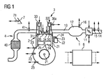
- An internal combustion engine ( FIG. 1 ) comprises an intake tract 1, an engine block 2, a cylinder head 3 and an exhaust tract 4.
- the intake tract 1 preferably comprises a throttle valve 11, furthermore a collector 12 and an intake manifold 13, which lead to a cylinder Z1 via an inlet channel into the engine block 2 is.
- the engine block 2 further comprises a crankshaft 21, which is coupled via a connecting rod 25 with the piston 24 of the cylinder Z1.
- the cylinder head 3 includes a valvetrain with a gas inlet valve 30, a gas outlet valve 31 and valve actuators 32, 33.
- the cylinder head 3 further comprises an injection valve 34 and a spark plug 35.
- the injection valve 34 may also be arranged in the intake manifold 13.
- the exhaust tract 4 comprises a catalyst 40, which is preferably designed as a three-way catalyst.
- a control device 6 is provided, which is associated with sensors which detect different measured variables and in each case determine the measured value of the measured variable.
- the control device 6 determines dependent on at least one of the measured variables manipulated variables, which are then converted into one or more actuating signals for controlling the actuators by means of corresponding actuators.
- the control device 6 can also be referred to as a device for controlling the internal combustion engine.
- the sensors are a pedal position sensor 71, which detects the position of an accelerator pedal 7, an air mass meter 14, which detects an air mass flow upstream of the throttle valve 11, a temperature sensor 15, which detects the intake air temperature, a crankshaft angle sensor 22, which detects a crankshaft angle CRK, then a Speed N is assigned, another temperature sensor 23, which detects a coolant temperature TCO, a camshaft angle sensor 36a, which detects a camshaft angle, a cylinder pressure sensor 37, which detects a pressure p in a combustion chamber of the cylinder Z1, and an exhaust gas probe 41 which a residual oxygen content of the exhaust gas detected and whose measurement signal is characteristic of the air / fuel ratio in the cylinder Z1.
- any subset of said sensors or additional sensors may be present.
- the actuators are, for example, the throttle valve 11, the gas inlet and gas outlet valves 30, 31, the injection valve 34 and the spark plug 35.
- cylinders Z2-Z4 may also be provided, to which corresponding actuators are then assigned.
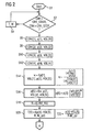
- a program for controlling the internal combustion engine is executed in a step S1 (FIG. FIG. 2 ), in which variables are initialized if necessary.
- a step S2 it is checked whether the current crankshaft angle CRK is greater than a starting crankshaft angle CRK_START. Further, it is checked whether the current crankshaft angle CRK is smaller than a stop crankshaft angle CRK_STOP.
- the starting crankshaft angle CRK_START is preferably selected at about 80 ° crankshaft angle after the ignition top dead center of the piston 24. At the start crankshaft angle CRK_START it is ensured that the combustion of the air / fuel mixture in the combustion chamber of the cylinder Z1 is safely completed.
- crankshaft angle CRK_STOP which is advantageously selected at about 100 ° after the ignition top dead center of the piston 24, it is ensured that the pressure in the cylinder still has a very high value.
- a detection of measured values of the pressure p in the combustion chamber of the cylinder Z1 taking place in the following steps S6 to S12 can be carried out with high quality by means of the cylinder pressure sensor 37.
- Cylinder pressure sensors 37 are usually designed to detect very high pressures. At lower pressures, they may have a larger measurement error.
- step S2 If the condition of step S2 is not fulfilled, the program is continued in a step S4, in which it is for a predetermined waiting time T_W remains before the condition of step S2 is checked again.
- a first measured value p [1] of the pressure in the combustion chamber of the cylinder Z1 is detected by means of the cylinder pressure sensor 37.
- the numbers given in parentheses for the following quantities refer to corresponding values for each crankshaft angle CRK.
- the crankshaft angle CRK [1] is 80 ° after the ignition top dead center
- p [1] is the measured value of the combustion chamber pressure associated with this crankshaft angle CRK [1]
- VOL [1] is the associated volume of the combustion chamber of the cylinder.
- a step S8 at a crankshaft angle CRK [2], which is, for example, 85 ° after the ignition top dead center, a second measured value p [2] of the pressure in the combustion chamber of the cylinder Z1 and the associated volume VOL [2] of the combustion chamber are detected determined.
- a crankshaft angle CRK [3] which is for example 90 ° after the ignition top dead center, a third measured value p [3] of the pressure in the combustion chamber of the cylinder Z1 is detected and the associated volume VOL [3 ] of the combustion chamber of the cylinder Z1 assigned.
- a fourth measured value p [4] of the pressure in the combustion chamber of the cylinder is detected and the corresponding volume VOL [4 ] of the combustion chamber of the cylinder Z1 assigned.
- a polytropic exponent ⁇ then becomes dependent on the first measured value p [1] of the pressure in the combustion chamber of the cylinder Z1, the volume assigned to it VOL [1] of the combustion chamber of the cylinder, the second measured value p [2] of the pressure in the combustion chamber of the cylinder Z1 and the associated volume VOL [2] determined.
- This is preferably done by means of a corresponding resolution of the polytope equation according to the polytropic exponent ⁇ , as shown by way of example in the right-hand part of step S14.
- the polytropic exponent is preferably averaged by multiplying the polytropic exponent K by means of different permutations of the value pairs of steps S6 to S12.
- measurement errors can be reduced and the polytropic exponent ⁇ can thus be determined even more accurately.
- a pressure p [5] in the combustion chamber of the cylinder Z1 is then determined, preferably immediately before the opening of the gas outlet valve 31, depending on the polytropic exponent K, from the second measured value p [2] of the pressure in the combustion chamber the volume VOL [2] associated therewith of the combustion chamber of the cylinder Z1 and the volume VOL [5] assigned to the pressure p [5] in the combustion chamber of the cylinder Z1.
- This is preferably done by means of the formula given on the right side of step S16.
- a suitable cylinder pressure sensor 37 it can also be done by a further detection of a measured value.
- the pressure p [5] in the combustion chamber of the cylinder Z1 can also be determined several times depending on further measured values of the pressure and then averaged.
- a gas constant R is preferably determined as a function of an actual value LAM_AV of the air / fuel ratio in the combustion chamber of the cylinder Z1, which is derived from the measurement signal of the oxygen probe 41.
- the gas constant R is assigned a predetermined value in step S18. Even so, a sufficient accuracy for the individual case in the further calculation can be ensured because the gas constant shows only a small variability.
- a step S20 the temperature T [5] of the exhaust gas in the cylinder Z1 is then dependent on the pressure p [5] in the combustion chamber of the cylinder Z1, the volume VOL [5] associated therewith, the gas constant R and that in the combustion chamber Cylinder Z1 located gas mass M_ZYL determined.
- the gas mass M_ZYL located in the cylinder Z1 can be determined, for example, by means of an intake manifold model depending on an opening degree of the throttle valve and / or the pressure in the collector 12 and / or the air mass flow detected by the air mass sensor 15 taking into account the fuel mass MFF metered in the cylinder Z1 ,
- the calculation of the temperature T [5] is preferably carried out by means of the general gas equation, as indicated on the right side of step S20.
- a pressure p [6] in the combustion chamber of the cylinder which is preferably the pressure at the time at which the gas outlet valve 31 has just closed, is determined by a measurement by means of the cylinder pressure sensor 37.
- a step S36 may be provided in which the pressure p [6] is directly associated with an ambient pressure p_AMB in a particularly simple manner.
- steps S38 and S40 are provided.
- step S38 a pressure p [6 '] associated with a crankshaft angle CRK that is within the crankshaft angle range in which the exhaust gas valve 31 is closed again is determined Gas inlet valve 30 is not opened again, and the time after the pressure p [6] attributable crankshaft angle is. Further, the volume VOL [6 '] to be assigned to the pressure p [6'] is temporarily stored.
- step S40 the pressure p [6] is then determined as a function of the polytropic exponent K, the pressure p [6 '], and the volumes VOL [6], VOL [6']. This is done in accordance with step S16.
- steps S42, S44 and S46 are provided.
- step S42 the pressure p [6 '] and the associated volume VOL [6'] are determined in accordance with the step S38. Furthermore, at least one further pressure p [6 "] is determined, which is assigned to a crankshaft angle CRK which lies within the crankshaft angle range in which the gas outlet valve 31 is closed again, but the gas inlet valve 30 is not yet reopened, and also in time Further, the volume VOL [6 "] to be assigned to the pressure p [6"] is temporarily stored.
- step S44 another polytropic exponent K 'is then determined as a function of the pressures p [6'], p [6 "] and the volumes VOL [6 '], VOL [6"], in accordance with the procedure of step S14. Also in step S44, the further polytropic exponent K 'can be determined as a function of further pressures and associated volumes, specifically as a mean further polytropic exponent.
- the step S46 corresponds to the step S40 with the difference that for determining the pressure p [6] the further or middle further polytropic exponent K 'is used.
- the pressure p [6] can also be determined several times with different further pressures in steps S38 or S46 and then averaged. Thus, measurement errors affect the individual measurements of the pressure less strong.
- a base temperature Tnorm [6] of the exhaust gas to be assigned to the pressure p [6] in the combustion chamber of the cylinder Z1 is determined as a function of the polytropic exponent ⁇ , the pressure p [6] and the pressure p [5] in FIG the combustion chamber of the cylinder Z1 and the temperature T [5] of the exhaust gas in the combustion chamber of the cylinder Z1 determined. This is preferably done by means of the relationship given on the right side of step S24. If step S44 was performed before step S24, the calculation of the base temperature Tnorm [6] may also be made dependent on the polytropic exponent K '.
- a temperature T [6] of the exhaust gas in the cylinder Z1 to be assigned to the pressure p [6] in the combustion chamber of the cylinder Z1 is then determined in a step S26 as a function of the base temperature Tnorm [6], an ambient temperature T_AMB and / or Vehicle speed V of a vehicle in which the internal combustion engine is arranged, and / or the coolant temperature TCO and / or an opening angle CRK_OP and / or a closing angle CRK_CL of the gas outlet valve 31.
- the temperature T [6] can be easily and with high precision. which is in particular the exhaust gas temperature at the time of closing the gas outlet valve 31, determined be without an exhaust back pressure model or a corresponding exhaust back pressure sensor is needed.
- an exhaust gas temperature sensor may also be omitted.
- the influence of the ambient temperature T_AMB, the vehicle speed V or the coolant temperature TCO or the opening angle CRK_OP or the closing angle CRK_CL of the gas outlet valve 31 to the temperature T [6] is preferably taken into account by means of corresponding characteristic curves or characteristic maps.
- an exhaust gas temperature T_KR in the exhaust gas tract and / or a pressure in the exhaust gas tract P_KR can also be taken into account.
- the subsequent steps S28 to S32 are executed when the internal combustion engine is operated by the space ignition method. If, however, the internal combustion engine is operated by means of another combustion method, then the temperature T [6], which is preferably the exhaust-gas temperature at the time of closing the gas outlet valve 31, can be an input variable for any functions of the control device.
- a first fuel mass MFF1 to be supplied is determined as a function of the temperature T [6] of the exhaust gas and a total of the fuel mass MFF to be supplied to the cylinder during a working cycle of the cylinder Z1.
- the first fuel mass MFF1 is metered during an intermediate compression of the cylinder Z1 in the combustion chamber of the cylinder Z1.
- intermediate compression is understood to mean the time duration after the gas outlet valve 31 has been closed and before the gas inlet valve 30 has been opened.
- the first supplied fuel mass MFF1 By metering the first amount of fuel MFF1 during the intermediate compression, an exothermic reaction and fractionation of the metered fuel occurs due to the still low oxygen content in the exhaust gas, resulting in radicals which accelerate the later combustion of the air / fuel mixture in the cylinder ,
- the first supplied fuel mass MFF1 so the timing of the air / fuel mixture can be set effectively. It plays a major role that the temperature T [6] can differ significantly from one working cycle to another and then again has a strong influence on the combustion of the next working cycle. This can be compensated for by appropriately setting the first fuel mass MFF1 and thus a precise adjustment of the ignition timing of the air / fuel mixture.
- a second fuel mass is also determined as a function of the total fuel mass MFF to be metered to the cylinder Z1 and the first fuel mass MFF1. This is preferably done by forming the difference between the total fuel mass MFF to be supplied to the cylinder Z1 and the first fuel mass MFF1.
- the second fuel mass MFF2 is metered into the cylinder Z1 only after the gas inlet valve 30 has been opened.
- a crankshaft angle CRK_MFF1 of the metering of the first fuel mass MFF1 is preferably determined as a function of the temperature T [6] of the exhaust gas.
- the ignition timing of the air / fuel mixture in the cylinder Z1 can also be advantageously influenced by the crankshaft angle CRK_MFF1 of the metering of the first fuel mass MFF1.
- a crankshaft angle CRK_MFF2 is determined as a function of the temperature T [6] of the exhaust gas, which also influences the ignition timing of the air / fuel mixture in the cylinder Z1.
- actuating signals SG for actuating the injection valve 34 are then determined.
- MFF2 be independent of the temperature T [6].
- the first fuel mass MFF1 may be independent of the temperature T [6] of the exhaust gas.
Landscapes
- Engineering & Computer Science (AREA)
- Chemical & Material Sciences (AREA)
- Combustion & Propulsion (AREA)
- Mechanical Engineering (AREA)
- General Engineering & Computer Science (AREA)
- Combined Controls Of Internal Combustion Engines (AREA)
- Electrical Control Of Air Or Fuel Supplied To Internal-Combustion Engine (AREA)
Claims (14)
- Procédé de commande d'un moteur à combustion interne comportant au moins un cylindre (Z1 à Z4) dans lequel une chambre de combustion est formée et auquel un piston (24) est associé, le moteur comprenant un conduit d'échappement (4) étant en communication avec la chambre de combustion du cylindre (Z1 à Z4) en fonction de la position d'une soupape d'échappement des gaz (31), et un capteur de pression de cylindre (37) qui saisit la pression (p) régnant dans la chambre de combustion du cylindre (Z1 à Z4), procédé dans lequel- un exposant de polytrope (κ) est déterminé en fonction d'au moins deux valeurs de mesure (p[1], p[2], p[3], p[4]) de la pression (p) dans la chambre de combustion, valeurs saisies au cours du temps moteur du cylindre (Z1 à Z4) après la fin de la combustion d'un mélange air/carburant dans le cylindre (Z1 à Z4) et avant l'ouverture de la soupape d'échappement des gaz (31),- une première température (T[5]) du gaz d'échappement est déterminée qui est caractéristique de la température des gaz d'échappement avant l'ouverture de la soupape d'échappement des gaz (31),- une deuxième température (T[6]) des gaz d'échappement restant dans la chambre de combustion du cylindre après la fermeture de la soupape d'échappement (31) est déterminée, et ce en fonction de la première température (T[5]) des gaz d'échappement, de la pression associée (p[5]) dans la chambre de combustion, de la pression (p[6]) dans la chambre de combustion après la fermeture de la soupape d'échappement des gaz (31), et de l'exposant de polytrope (K), et- un signal de commande (SG) pour commander un actionneur du moteur à combustion interne est généré en fonction de la deuxième température (T[6]) des gaz d'échappement.
- Procédé selon la revendication 1, dans lequel les valeurs de mesure (p[1], p[2], p[3], p[4]) de la pression (p) des gaz d'échappement dans la chambre de combustion du cylindre (Z1 à Z4) sont saisies sous un angle de vilebrequin (CRK) plus grand qu'un angle de vilebrequin prédéterminé de telle sorte que la combustion du mélange air/carburant soit terminée.
- Procédé selon la revendication 2, dans lequel l'angle de vilebrequin prédéterminé est plus grand que, ou égal à, environ 80° après le point mort haut du piston (24).
- Procédé selon la revendication 2 ou 3, dans lequel l'angle de vilebrequin prédéterminé est plus grand que, ou égal à, environ 100° après le point mort haut du piston (24).
- Procédé selon l'une des revendications précédentes, dans lequel la première température (T[5]) des gaz d'échappement est déterminée en fonction d'une pression (p[5]) dans la chambre de combustion, pression déterminée en fonction d'une des valeurs de mesure (p[1], p[2], p[3], p[4]) de la pression (p) dans la chambre de combustion ; de la grandeur caractéristique du volume (VOL[2]) de la chambre de combustion associé à la valeur correspondante (p[1], p[2], p[3], p[4]) de la pression (p) ; de la grandeur caractéristique du volume (VOL[5]) de la chambre de combustion où les gaz d'échappement sont à la première température ; et de l'exposant de polytrope (K) .
- Procédé selon l'une des revendications précédentes, dans lequel la première température (T[5]) des gaz d'échappement est déterminée à l'aide de l'équation générale des gaz, la constante des gaz (R) étant une valeur fixe prédéterminée.
- Procédé selon l'une des revendications 1 à 6, dans lequel la première température des gaz d'échappement est déterminée à l'aide de l'équation générale des gaz, et une constante des gaz (R) est établie en fonction du rapport air/carburant dans la chambre de combustion du cylindre (Z1 à Z4).
- Procédé selon l'une des revendications précédentes, dans lequel la pression (p[6]) dans la chambre de combustion après la fermeture de la soupape d'échappement des gaz (31) est approchée par une valeur de pression prédéterminée, et la deuxième température des gaz d'échappement est déterminée en fonction d'un paramètre d'environnement et/ou d'un nombre de tours (n) et/ou de l'angle de vilebrequin d'ouverture ou de fermeture de la soupape d'échappement des gaz et/ou d'une température de liquide de refroidissement (TCO).
- Procédé selon l'une des revendications précédentes, dans lequel la pression (p[6]) dans la chambre de combustion est déterminée après la fermeture de la soupape d'échappement des gaz (31) en fonction d'au moins une autre pression (p[6']) et des volumes (VOL[6'], VOL[6]) associés à la au moins autre pression (p[6']) et à la pression (p[6]) régnant dans la chambre de combustion après la fermeture de la soupape d'échappement des gaz (31), l'autre pression (p[6']) étant associée à un angle de vilebrequin CRK) situé à l'intérieur de la plage des angles de vilebrequin dans laquelle la soupape d'échappement des gaz (31) est de nouveau fermée et la soupape d'admission des gaz (30) n'est pas encore ouverte, l'autre pression (p[6']) étant saisie après la saisie de la pression (p[6]).
- Procédé selon la revendication 9, dans lequel un autre exposant de polytrope (K') est déterminé en fonction de la au moins une autre pression (p[6']), de l'autre pression encore (p[6"]), et des volumes (VOL[6'], VOL[6"]) associés à la au moins une autre pression (p[6']) et à l'autre pression encore (p[6"]) dans la chambre de combustion après la fermeture de la soupape d'échappement des gaz (31), l'autre pression encore (p[6"]) étant associée à un angle de vilebrequin (CRK) situé à l'intérieur de la plage des angles de vilebrequin dans laquelle la soupape d'échappement des gaz (31) est de nouveau fermée et la soupape d'admission des gaz (30) n'est pas encore ouverte, l'autre pression encore (p[6"]) étant saisie après la saisie de la pression (p[6]).
- Procédé selon l'une des revendications précédentes, dans lequel une première masse de carburant (MFF1) devant être dosée dans la chambre de combustion du cylindre (Z1 à Z4) après la fermeture de la soupape d'échappement des gaz (31) et avant l'ouverture de la soupape d'admission des gaz (30), est déterminée en fonction de la deuxième température (T[6]) des gaz d'échappement, et la soupape d'injection (34) est commandée en conséquence.
- Procédé selon la revendication 11, dans lequel un angle de vilebrequin (CRK_MFF1) sous lequel une première masse de carburant (MFF1) est dosée est déterminé en fonction de la deuxième température (T[6]).
- Procédé selon l'une des revendications 11 ou 12, dans lequel un angle de vilebrequin (CRK MFF2) sous lequel une deuxième masse de carburant (MFF2) est dosée, est déterminé en fonction de la deuxième température (T[6]), la deuxième masse de carburant (MFF2) étant dosée dans le cylindre (Z1 à Z4) après l'ouverture de la soupape d'admission des gaz.
- Dispositif de commande d'un moteur à combustion interne comportant au moins un cylindre (Z1 à Z4) dans lequel une chambre de combustion est formée, et auquel un piston (24) est associé, comprenant un conduit d'échappement (4) en communication avec la chambre de combustion du cylindre (Z1 à Z4) en fonction de la position d'une soupape d'échappement des gaz (31), et un capteur de pression de cylindre (37) qui saisit la pression (p) régnant dans la chambre de combustion du cylindre (Z1 à Z4), et comprenant des unités qui- déterminent un exposant de polytrope (K) en fonction d'au moins deux valeurs de mesure (p[1], p[2], p[3], p[4]) de la pression (p) dans la chambre de combustion, saisies au cours du temps moteur du cylindre (Z1 à Z4) après la fin de la combustion d'un mélange air/carburant dans le cylindre (Z1 à Z4) et avant l'ouverture de la soupape d'échappement des gaz (31),- déterminent une première température (T[5]) des gaz d'échappement qui est caractéristique de la température des gaz d'échappement avant l'ouverture de la soupape d'échappement des gaz (31),- déterminent une deuxième température (T[6]) du gaz d'échappement restant dans la chambre de combustion du cylindre après la fermeture de la soupape d'échappement des gaz (31), et ce en fonction de la première température (T[5]) du gaz d'échappement, de la pression y associée (p[5]) dans la chambre de combustion, de la pression (p[6]) dans la chambre de combustion après la fermeture de la soupape d'échappement des gaz (31) et de l'exposant de polytrope (κ), et- génèrent un signal de commande (SG) pour commander un actionneur du moteur à combustion interne en fonction de la deuxième température (T[6]) des gaz d'échappement.
Applications Claiming Priority (2)
| Application Number | Priority Date | Filing Date | Title |
|---|---|---|---|
| DE102004038122A DE102004038122B4 (de) | 2004-08-05 | 2004-08-05 | Verfahren und Vorrichtung zum Steuern einer Brennkraftmaschine |
| PCT/EP2005/053496 WO2006015928A1 (fr) | 2004-08-05 | 2005-07-20 | Procede et dispositif de commande d'un moteur a combustion interne |
Publications (2)
| Publication Number | Publication Date |
|---|---|
| EP1774162A1 EP1774162A1 (fr) | 2007-04-18 |
| EP1774162B1 true EP1774162B1 (fr) | 2008-05-07 |
Family
ID=35219279
Family Applications (1)
| Application Number | Title | Priority Date | Filing Date |
|---|---|---|---|
| EP05777714A Expired - Lifetime EP1774162B1 (fr) | 2004-08-05 | 2005-07-20 | Procede et dispositif de commande d'un moteur a combustion interne |
Country Status (4)
| Country | Link |
|---|---|
| US (1) | US7826960B2 (fr) |
| EP (1) | EP1774162B1 (fr) |
| DE (2) | DE102004038122B4 (fr) |
| WO (1) | WO2006015928A1 (fr) |
Families Citing this family (10)
| Publication number | Priority date | Publication date | Assignee | Title |
|---|---|---|---|---|
| DE102004038121B3 (de) * | 2004-08-05 | 2006-06-01 | Siemens Ag | Verfahren und Vorrichtung zum Steuern einer Brennkraftmaschine |
| GB0601727D0 (en) * | 2006-01-27 | 2006-03-08 | Ricardo Uk Ltd | A Method Of Identifying Engine Gas Composition |
| US8322129B2 (en) * | 2006-02-16 | 2012-12-04 | Cummins, Inc. | Method for controlling turbine outlet temperatures in a diesel engine |
| DE102006033484B4 (de) | 2006-07-19 | 2018-08-23 | Robert Bosch Gmbh | Verfahren und Vorrichtung zur Steuerung einer Brennkraftmaschine |
| US8620565B2 (en) * | 2009-12-21 | 2013-12-31 | International Engine Intellectual Property Company, Llc. | Control system and method for limiting engine torque based on engine oil pressure and engine oil temperature data |
| DE102011106544A1 (de) | 2011-06-16 | 2012-12-20 | Fev Gmbh | Verfahren und Vorrichtung zum Betrieb eines Verbrennungsmotors bei kontrollierter Selbstzündung |
| JP5904197B2 (ja) * | 2013-12-11 | 2016-04-13 | トヨタ自動車株式会社 | 内燃機関の診断装置 |
| SE541091C2 (en) * | 2016-03-23 | 2019-04-02 | Scania Cv Ab | A method and a system for adapting engine control of a gas engine in a vehicle |
| SE540143C2 (en) * | 2016-03-23 | 2018-04-10 | Scania Cv Ab | A method and a system for determining the specific gas constant and the stoichiometric air fuel ratio of a fuel gas for a gas engine |
| DE102016207135B3 (de) * | 2016-04-27 | 2017-05-11 | Continental Automotive Gmbh | Brennkraftmaschine und Betriebsverfahren für eine Brennkraftmaschine |
Family Cites Families (13)
| Publication number | Priority date | Publication date | Assignee | Title |
|---|---|---|---|---|
| US4624229A (en) * | 1985-10-29 | 1986-11-25 | General Motors Corporation | Engine combustion control with dilution flow by pressure ratio management |
| US4621603A (en) * | 1985-10-29 | 1986-11-11 | General Motors Corporation | Engine combustion control with fuel balancing by pressure ratio management |
| DE58903237D1 (de) * | 1989-05-23 | 1993-02-18 | Siemens Ag | Verfahren zur bestimmung des brennraumdruckes in einem zylinder einer brennkraftmaschine mit einem drucksensor. |
| US5219227A (en) * | 1990-08-13 | 1993-06-15 | Barrack Technology Limited | Method and apparatus for determining burned gas temperature, trapped mass and NOx emissions in an internal combustion engine |
| DE19900738C1 (de) * | 1999-01-12 | 2000-06-15 | Daimler Chrysler Ag | Verfahren und Vorrichtung zur Bestimmung eines Brennraumdruckverlaufs bei einer Brennkraftmaschine |
| DE19952096C2 (de) * | 1999-10-29 | 2001-10-11 | Daimler Chrysler Ag | Brennkraftmaschine mit Kompressionszündung |
| JP4016568B2 (ja) * | 2000-03-30 | 2007-12-05 | 日産自動車株式会社 | ガソリン自己着火式内燃機関 |
| JP3931549B2 (ja) * | 2000-10-19 | 2007-06-20 | 日産自動車株式会社 | 内燃機関のバルブタイミング制御装置 |
| US6484694B2 (en) * | 2000-12-05 | 2002-11-26 | Detroit Diesel Corporation | Method of controlling an internal combustion engine |
| GB0112338D0 (en) * | 2001-05-21 | 2001-07-11 | Ricardo Consulting Eng | Improved engine management |
| DE102004038121B3 (de) * | 2004-08-05 | 2006-06-01 | Siemens Ag | Verfahren und Vorrichtung zum Steuern einer Brennkraftmaschine |
| US7418336B2 (en) * | 2006-04-24 | 2008-08-26 | Gm Global Technology Operations, Inc. | Method for internal combustion engine control using pressure ratios |
| US7454286B2 (en) * | 2006-12-20 | 2008-11-18 | Delphi Technologies, Inc. | Combustion control in an internal combustion engine |
-
2004
- 2004-08-05 DE DE102004038122A patent/DE102004038122B4/de not_active Expired - Fee Related
-
2005
- 2005-07-20 US US11/659,404 patent/US7826960B2/en not_active Expired - Fee Related
- 2005-07-20 DE DE502005004037T patent/DE502005004037D1/de not_active Expired - Lifetime
- 2005-07-20 WO PCT/EP2005/053496 patent/WO2006015928A1/fr not_active Ceased
- 2005-07-20 EP EP05777714A patent/EP1774162B1/fr not_active Expired - Lifetime
Also Published As
| Publication number | Publication date |
|---|---|
| DE102004038122A1 (de) | 2006-02-23 |
| DE502005004037D1 (de) | 2008-06-19 |
| DE102004038122B4 (de) | 2006-07-20 |
| US7826960B2 (en) | 2010-11-02 |
| EP1774162A1 (fr) | 2007-04-18 |
| US20080183364A1 (en) | 2008-07-31 |
| WO2006015928A1 (fr) | 2006-02-16 |
Similar Documents
| Publication | Publication Date | Title |
|---|---|---|
| DE102008004360A1 (de) | Verfahren und Vorrichtung zum Steuern eines selbstzündenden Verbrennungsmotors | |
| DE102005009104B3 (de) | Verfahren und Vorrichtung zum Steuern einer Brennkraftmaschine | |
| DE112008000616T5 (de) | Verfahren und Vorrichtung zum Steuern der Kraftstoffeinspritzung in einem Motor mit homogener Kompressionszündung | |
| DE10233612B4 (de) | Verfahren und Vorrichtung zum Steuern des Verbrennungsvorganges einer HCCI-Brennkraftmaschine | |
| EP1774162B1 (fr) | Procede et dispositif de commande d'un moteur a combustion interne | |
| EP1774161B1 (fr) | Procede et dispositif pour commander un moteur a combustion interne | |
| EP1749149B1 (fr) | Procede pour detecter un rapport air/carburant, specifique a chaque cylindre, dans un moteur a combustion interne | |
| DE102004062408A1 (de) | Verfahren und Vorrichtung zum Ermitteln einer Sauerstoffspeicherkapazität des Abgaskatalysators einer Brennkraftmaschine und Verfahren und Vorrichtung zum Ermitteln einer Dynamik-Zeitdauer für Abgassonden einer Brennkraftmaschine | |
| DE102009028638A1 (de) | Verfahren zum Ausgleichen von Gaswechsel-Verlusten zwischen Brennräumen eines Ottomotors | |
| DE102006019894B3 (de) | Verfahren und Vorrichtung zum Betreiben einer Brennkraftmaschine | |
| DE10006264C1 (de) | Brennkraftmaschine und Verfahren zum Betrieb einer Brennkraftmaschine | |
| DE102011004068B3 (de) | Verfahren und Steuervorrichtung zum Gleichstellen mehrerer Zylinder einer Brennkraftmaschine | |
| DE102007057142A1 (de) | Verfahren zum Betreiben einer Brennkraftmaschine | |
| EP1706603B1 (fr) | Procede et dispositif de determination d'une phase d'un moteur a combustion interne | |
| DE102004039216B4 (de) | Verfahren und Vorrichtung zum Steuern oder zur Diagnose einer Brennkraftmaschine | |
| DE102007045264B4 (de) | Verfahren und Vorrichtung zum Betreiben einer Brennkraftmaschine | |
| DE102005004442B4 (de) | Verfahren und Vorrichtung zum Steuern einer Brennkraftmaschine | |
| DE102006043702B3 (de) | Verfahren und Vorrichtung zum Betreiben einer Brennkraftmaschine | |
| DE102013213871B4 (de) | Verfahren und Vorrichtung zum Betreiben einer Brennkraftmaschine | |
| DE102004052742A1 (de) | Verfahren zum Betrieb einer Brennkraftmaschine | |
| DE10304242B3 (de) | Verfahren zur Ermittlung eines Parameters einer Verbrennung in einem Zylinder einer mehrzylindrigen Brennkraftmaschine, Brennkraftmaschine mit einer mehrflutiger Abgasanlage und mehrflutige Abgasanlage | |
| DE102007051552A1 (de) | Verfahren zum Betreiben einer Brennkraftmaschine mit mehreren Zylindern | |
| WO2005031143A1 (fr) | Procede et dispositif pour piloter un moteur a combustion interne | |
| DE102006042969B4 (de) | Verfahren und Vorrichtung zum Betreiben einer Brennkraftmaschine | |
| DE102006022994A1 (de) | Verfahren zum Betreiben einer Brennkraftmaschine |
Legal Events
| Date | Code | Title | Description |
|---|---|---|---|
| PUAI | Public reference made under article 153(3) epc to a published international application that has entered the european phase |
Free format text: ORIGINAL CODE: 0009012 |
|
| 17P | Request for examination filed |
Effective date: 20061229 |
|
| AK | Designated contracting states |
Kind code of ref document: A1 Designated state(s): DE FR GB IT |
|
| DAX | Request for extension of the european patent (deleted) | ||
| RBV | Designated contracting states (corrected) |
Designated state(s): DE FR GB IT |
|
| GRAP | Despatch of communication of intention to grant a patent |
Free format text: ORIGINAL CODE: EPIDOSNIGR1 |
|
| GRAS | Grant fee paid |
Free format text: ORIGINAL CODE: EPIDOSNIGR3 |
|
| GRAA | (expected) grant |
Free format text: ORIGINAL CODE: 0009210 |
|
| AK | Designated contracting states |
Kind code of ref document: B1 Designated state(s): DE FR GB IT |
|
| REG | Reference to a national code |
Ref country code: GB Ref legal event code: FG4D Free format text: NOT ENGLISH |
|
| RAP2 | Party data changed (patent owner data changed or rights of a patent transferred) |
Owner name: CONTINENTAL AUTOMOTIVE GMBH |
|
| REF | Corresponds to: |
Ref document number: 502005004037 Country of ref document: DE Date of ref document: 20080619 Kind code of ref document: P |
|
| PLBE | No opposition filed within time limit |
Free format text: ORIGINAL CODE: 0009261 |
|
| STAA | Information on the status of an ep patent application or granted ep patent |
Free format text: STATUS: NO OPPOSITION FILED WITHIN TIME LIMIT |
|
| 26N | No opposition filed |
Effective date: 20090210 |
|
| REG | Reference to a national code |
Ref country code: FR Ref legal event code: TP |
|
| PGFP | Annual fee paid to national office [announced via postgrant information from national office to epo] |
Ref country code: FR Payment date: 20130722 Year of fee payment: 9 Ref country code: GB Payment date: 20130719 Year of fee payment: 9 |
|
| PGFP | Annual fee paid to national office [announced via postgrant information from national office to epo] |
Ref country code: IT Payment date: 20130731 Year of fee payment: 9 |
|
| GBPC | Gb: european patent ceased through non-payment of renewal fee |
Effective date: 20140720 |
|
| REG | Reference to a national code |
Ref country code: FR Ref legal event code: ST Effective date: 20150331 |
|
| PG25 | Lapsed in a contracting state [announced via postgrant information from national office to epo] |
Ref country code: IT Free format text: LAPSE BECAUSE OF NON-PAYMENT OF DUE FEES Effective date: 20140720 |
|
| PG25 | Lapsed in a contracting state [announced via postgrant information from national office to epo] |
Ref country code: GB Free format text: LAPSE BECAUSE OF NON-PAYMENT OF DUE FEES Effective date: 20140720 Ref country code: FR Free format text: LAPSE BECAUSE OF NON-PAYMENT OF DUE FEES Effective date: 20140731 |
|
| REG | Reference to a national code |
Ref country code: DE Ref legal event code: R084 Ref document number: 502005004037 Country of ref document: DE |
|
| REG | Reference to a national code |
Ref country code: DE Ref legal event code: R081 Ref document number: 502005004037 Country of ref document: DE Owner name: VITESCO TECHNOLOGIES GMBH, DE Free format text: FORMER OWNER: CONTINENTAL AUTOMOTIVE GMBH, 30165 HANNOVER, DE |
|
| REG | Reference to a national code |
Ref country code: DE Ref legal event code: R081 Ref document number: 502005004037 Country of ref document: DE Owner name: VITESCO TECHNOLOGIES GMBH, DE Free format text: FORMER OWNER: VITESCO TECHNOLOGIES GMBH, 30165 HANNOVER, DE |
|
| PGFP | Annual fee paid to national office [announced via postgrant information from national office to epo] |
Ref country code: DE Payment date: 20220628 Year of fee payment: 18 |
|
| REG | Reference to a national code |
Ref country code: DE Ref legal event code: R119 Ref document number: 502005004037 Country of ref document: DE |
|
| PG25 | Lapsed in a contracting state [announced via postgrant information from national office to epo] |
Ref country code: DE Free format text: LAPSE BECAUSE OF NON-PAYMENT OF DUE FEES Effective date: 20240201 |