EP1774360B1 - Hochauflösende bilder aus reflexionswellenenergie - Google Patents
Hochauflösende bilder aus reflexionswellenenergie Download PDFInfo
- Publication number
- EP1774360B1 EP1774360B1 EP05763489A EP05763489A EP1774360B1 EP 1774360 B1 EP1774360 B1 EP 1774360B1 EP 05763489 A EP05763489 A EP 05763489A EP 05763489 A EP05763489 A EP 05763489A EP 1774360 B1 EP1774360 B1 EP 1774360B1
- Authority
- EP
- European Patent Office
- Prior art keywords
- signals
- producing
- real
- transducers
- channel signals
- Prior art date
- Legal status (The legal status is an assumption and is not a legal conclusion. Google has not performed a legal analysis and makes no representation as to the accuracy of the status listed.)
- Expired - Lifetime
Links
Images


Classifications
-
- G—PHYSICS
- G01—MEASURING; TESTING
- G01S—RADIO DIRECTION-FINDING; RADIO NAVIGATION; DETERMINING DISTANCE OR VELOCITY BY USE OF RADIO WAVES; LOCATING OR PRESENCE-DETECTING BY USE OF THE REFLECTION OR RERADIATION OF RADIO WAVES; ANALOGOUS ARRANGEMENTS USING OTHER WAVES
- G01S7/00—Details of systems according to groups G01S13/00, G01S15/00, G01S17/00
- G01S7/52—Details of systems according to groups G01S13/00, G01S15/00, G01S17/00 of systems according to group G01S15/00
- G01S7/523—Details of pulse systems
- G01S7/526—Receivers
- G01S7/527—Extracting wanted echo signals
- G01S7/5273—Extracting wanted echo signals using digital techniques
-
- G—PHYSICS
- G01—MEASURING; TESTING
- G01S—RADIO DIRECTION-FINDING; RADIO NAVIGATION; DETERMINING DISTANCE OR VELOCITY BY USE OF RADIO WAVES; LOCATING OR PRESENCE-DETECTING BY USE OF THE REFLECTION OR RERADIATION OF RADIO WAVES; ANALOGOUS ARRANGEMENTS USING OTHER WAVES
- G01S15/00—Systems using the reflection or reradiation of acoustic waves, e.g. sonar systems
- G01S15/88—Sonar systems specially adapted for specific applications
- G01S15/89—Sonar systems specially adapted for specific applications for mapping or imaging
-
- G—PHYSICS
- G01—MEASURING; TESTING
- G01S—RADIO DIRECTION-FINDING; RADIO NAVIGATION; DETERMINING DISTANCE OR VELOCITY BY USE OF RADIO WAVES; LOCATING OR PRESENCE-DETECTING BY USE OF THE REFLECTION OR RERADIATION OF RADIO WAVES; ANALOGOUS ARRANGEMENTS USING OTHER WAVES
- G01S7/00—Details of systems according to groups G01S13/00, G01S15/00, G01S17/00
- G01S7/52—Details of systems according to groups G01S13/00, G01S15/00, G01S17/00 of systems according to group G01S15/00
- G01S7/523—Details of pulse systems
- G01S7/526—Receivers
- G01S7/53—Means for transforming coordinates or for evaluating data, e.g. using computers
-
- G—PHYSICS
- G01—MEASURING; TESTING
- G01S—RADIO DIRECTION-FINDING; RADIO NAVIGATION; DETERMINING DISTANCE OR VELOCITY BY USE OF RADIO WAVES; LOCATING OR PRESENCE-DETECTING BY USE OF THE REFLECTION OR RERADIATION OF RADIO WAVES; ANALOGOUS ARRANGEMENTS USING OTHER WAVES
- G01S7/00—Details of systems according to groups G01S13/00, G01S15/00, G01S17/00
- G01S7/52—Details of systems according to groups G01S13/00, G01S15/00, G01S17/00 of systems according to group G01S15/00
- G01S7/56—Display arrangements
Definitions
- This invention relates to imaging systems based on receiving reflected wave energy and more particularly to apparatus, methods, media and signals for producing high resolution images from reflected wave energy.
- Imaging systems based on receiving reflected wave energy conventionally employ electromagnetic waves or acoustic waves to produce a reflected signal from a distant object. This reflected signal is interpreted and used to produce a display image. Various techniques may be used to interpret the reflected signal.
- Each transducer produces a signal in response to reflected wave energy and each signal is processed to produce a focusing effect whereby the array appears to receive reflected wave energy in a steerable beam.
- this steerable beam can be swept through a plurality of angles to scan an area in which reflected wave energy is present.
- Transducer arrays can be costly however, and require significant processing capability to adequately process signals from each transducer element to ultimately produce an image.
- a process for producing signals for controlling a display to produce an image in an imaging system employing a plurality of transducers involves producing first and second beam signals in response to delayed channel signals associated with respective transducers.
- the delayed channel signals represent real and imaginary components of time domain signals associated with respective transducers suitably delayed to focus a receive beam pattern of the transducers at a beam angle.
- Each of the first and second beam signals includes separate real and imaginary component representations.
- the process further involves combining the real and imaginary components of the first and second beam signals, to produce a composite beam signal, the composite beam signal including separate real and imaginary component representations.
- the process further involves performing a trigonometric expansion on normalized values of the real and imaginary component representations of the composite beam signal to produce a plurality of expanded values and producing illumination signals in response to the expanded values, for illuminating pixels on the display.
- the process may involve receiving the delayed channel signals.
- the process may involve producing the delayed channel signals.
- the delayed channel signals may comprise producing the delayed channel signals in response to channel signals and delay signals associated with the respective transducers,
- Each channel signal may represent a signal received at a corresponding transducer and include separate real and imaginary component representations and the delay signals may include separate cosine and sine delay components of a delay dependent on a desired beam angle at which the transducers are to be focused.
- Each of the delayed channel signals may include separate real and imaginary component representations.
- the process may further include receiving the channel signals.
- the process may further include producing the channel signals.
- the channel signals may comprise producing frequency domain representations of respective time sampled representations of respective signals received at respective transducers and producing time domain representations of the respective signals in response to the frequency domain representations, the time domain representations comprising real and imaginary components.
- the process may further include receiving the delay signals.
- the process may further include receiving the channel signals and the delay signals may be received before the channel signals are received.
- the process may further include producing the delay signals.
- the process may further include receiving the channel signals and the delay signals may be produced before the channel signals are received.
- Producing the delay signals may comprise producing the delay signals in response to transducer spacing, angular frequency of wave energy received at the transducers, desired beam angle and speed of the wave energy in an area of a medium for which the image is to be produced.
- the process may further include producing a normalized composite beam signal comprising a plurality of normalized values, in response to the real and imaginary component representations of the composite beam signal and for each of the normalized values calculating a real part of the product of the first beam signal and the complex conjugate of the second beam signal.
- Producing a normalized composite beam signal may comprise scaling the real part of a product of the first beam signal and a complex conjugate of the second beam signal, by a magnitude value.
- the process may further include producing the magnitude value in response to the real and imaginary components of the first and second beam signals.
- Performing a trigonometric expansion may comprise performing a power expansion on each of the normalized values.
- Performing a trigonometric expansion may comprise performing a sum of Chebyshev polynomials on each of the normalized values.
- the process may further include illuminating pixels on the display in response to the illumination signals.
- the process may involve conducting the process above and/or variations thereof for each of a plurality of beam angles to produce a set of illumination signals for each the beam angle.
- the process may further include defining the plurality of beam angles.
- the process may further include mapping respective sets of illumination values to respective rays of pixels on the display, each the ray corresponding to a respective beam angle, the illumination signals being operable to cause pixels along a given ray to be illuminated in response to corresponding illumination values.
- a computer readable medium encoded with instructions for directing a processor to execute the process above.
- a computer readable signal encoded with instructions for directing a processor to execute the process above.
- an apparatus for producing signals for controlling a display to produce an image in an imaging system employing a plurality of transducers includes provisions for producing first and second beam signals in response to delayed channel signals associated with transducers, the delayed channel signals representing real and imaginary components of time domain signals associated with respective transducers suitably delayed to focus a receive beam pattern of the transducers at a beam angle, each of the first and second beam signals including separate real and imaginary component representations.
- the apparatus further includes provisions for combining the real and imaginary components of the first and second beam signals, to produce a composite beam signal, the composite beam signal including separate real and imaginary component representations, provisions for performing a trigonometric expansion on normalized values of the real and imaginary component representations of the composite bean signal to produce a plurality of expanded values and provisions for producing illumination signals, in response to the expanded values, the illumination signals being operable to be received by the display for illuminating pixels on the display.
- the apparatus may further include provisions for receiving the delayed channel signals.
- the apparatus may further include provisions for producing the delayed channel signals.
- the provisions for producing the delayed channel signals may comprise provisions for producing the delayed channel signals in response to channel signals and delay signals associated with the transducers,
- Each channel signal may represent a signal received at a corresponding transducer and may include separate real and imaginary component representations and the delay signals may include separate cosine and sine delay components of a delay dependent on a desired beam angle at which the transducers are to be focused.
- Each of the delayed channel signals may include separate real and imaginary component representations.
- the apparatus may further include provisions for receiving the channel signals.
- the apparatus may further include provisions for producing the channel signals.
- the provisions for producing the channel signals may comprise provisions for producing frequency domain representations of respective time sampled representations of respective signals received at respective transducers and provisions for producing time domain representations of the respective signals in response to the frequency domain representations.
- the time domain representations may comprise real and imaginary components.
- the apparatus may further include provisions for receiving the delay signals.
- the apparatus may further include provisions for receiving the channel signals and the delay signals may be received before the channel signals are received.
- the apparatus may further include provisions for producing the delay signals.
- the apparatus may further include provisions for receiving the channel signals and the delay signals may be produced before the channel signals are received.
- the provisions for producing the delay signals may comprise provisions for producing the delay signals in response to transducer spacing, angular frequency of wave energy received at the transducers, desired beam angle and speed of the wave energy in an area of a medium for which the image is to be produced.
- the apparatus may further include provisions for producing a normalized composite beam signal comprising a plurality of normalized values in response to the real and imaginary component representations of the composite beam signal and the provisions for producing a normalized composite beam signal may include provisions for, for each of the normalized values, calculating a real part of the product of the first beam signal and a complex conjugate of the second beam signal.
- the provisions for normalizing may comprise provisions for scaling the real part of a product of the first beam signal and the complex conjugate of the second beam signal, by a magnitude value.
- the apparatus may further include provisions for producing the magnitude value in response to the real and imaginary components of the first and second beam signals.
- the provisions for performing a trigonometric expansion may comprise provisions for performing a power expansion on each of the normalized values.
- the provisions for performing a trigonometric expansion may comprise provisions for performing a sum of Chebyshev polynomials on each of the normalized values.
- the apparatus may further include provisions for illuminating pixels on the display in response to the expanded values.
- the apparatus may further include provisions for causing the apparatus to produce a set of illumination signals for a plurality of the beam angles.
- the apparatus may further include provisions for defining the plurality of beam angles.
- the apparatus may further include provisions for mapping respective sets of illumination values to respective rays of pixels on the display, each of the rays corresponding to a respective beam angle, the illumination signals being operable to cause pixels along a given ray to be illuminated in response to corresponding illumination values.
- an apparatus for producing signals for controlling a display to produce an image in an imaging system employing a plurality of transducers includes memory for storing delayed channel signals associated with respective transducers, the delayed channel signals representing real and imaginary components of time domain signals associated with respective transducers suitably delayed to focus a receive beam pattern of the transducers at a beam angle.
- the apparatus further includes a processor in communication with the memory and operably configured to produce first and second beam signals in response to the delayed channel signals, each of the first and second beam signals including separate real and imaginary component representations.
- the processor is further operably configured to combine the real and imaginary components of the first and second beam signals, to produce a composite beam signal, the composite beam signal including separate real and imaginary component representations, perform a trigonometric expansion on normalized values of the real and imaginary component representations of the composite beam signal to produce a plurality of expanded values and produce illumination signals in response to the expanded values, for use by the display, for illuminating pixels on the display.
- the apparatus may further include an input operably coupled to the processor for receiving the delayed channel signals.
- the processor may be operably configured to produce the delayed channel signals.
- the apparatus may further include memory for storing channel signals and delay signals associated with the respective transducers, each channel signal representing a signal received at a corresponding transducer and including separate real and imaginary component representations, and the delay signals including separate cosine and sine delay components of a delay dependent on a desired beam angle at which the transducers are to be focused, and the processor may be operably configured to produce the delayed channel signals in response to the channel signals and delay signals, each of the delayed channel signals including separate real and imaginary component representations.
- the apparatus may further include an input coupled to the processor for receiving the channel signals.
- the processor may be operably configured to produce the channel signals.
- the apparatus may further include an input operably coupled to the processor to enable the processor to receive and store in the memory respective time sampled representations of respective signals received at respective transducers and the processor may be operably configured to produce the channel signals by producing frequency domain representations of respective time sampled representations of respective signals received at respective transducers and to produce time domain representations of the respective signals in response to the frequency domain representations, the time domain representations comprising real and imaginary components.
- the apparatus may further include an input operably coupled to the processor to enable the processor to receive and store in the memory the delay signals.
- the apparatus may further include an input operably coupled to the processor to enable the processor to receive the channel signals and wherein the delay signals may be received before the channel signals are received.
- the processor may be operably configured to produce the delay signals.
- the apparatus may further include an input operably coupled to the processor for receiving the channel signals and the processor may be operably configured to produce the delay signals before the channel signals are received.
- the apparatus may further include memory for storing representations of transducer spacing, angular frequency of wave energy received at the transducers, desired beam angle and speed of the wave energy in an area of a medium for which the image is to be produced, and the processor may be operably configured to produce the delay signals in response to the representations of transducer spacing, angular frequency of wave energy received at the transducers, desired beam angle and speed of the wave energy in an area of a medium for which the image is to be produced.
- the processor may be operably configured to produce a normalized composite beam signal comprising a plurality of normalized values in response to the real and imaginary component representations of the composite beam signal and for each of the normalized values, calculating a real part of a product of the first beam signal and a complex conjugate of the second beam signal.
- the processor may be operably configured to scale the real part of the product of the first beam signal and the complex conjugate of the second beam signal, by a magnitude value.
- the processor may be operably configured to produce the magnitude value in response to the real and imaginary components of the first and second beam signals.
- the processor may be operably configured to perform the trigonometric expansion by performing a power expansion on each of the normalized values.
- the processor may be operably configured to perform the trigonometric expansion by performing a sum of Chebyshev polynomials on each of the normalized values.
- the processor may be operably configured to produce illumination signals operable to be received by an LCD display.
- the processor may be operably configured to, for each of a plurality of beam angles, produce a set of illumination signals for each beam angle.
- the processor may be operably configured to define the plurality of beam angles.
- the processor may be operably configured to map respective sets of illumination values to respective rays of pixels on the display, each the ray corresponding to a respective beam angle, the illumination signals being operable to cause pixels along a given ray to be illuminated in response to corresponding illumination values.
- an imaging system according to a first embodiment of the invention is shown generally at 10.
- the system includes a sonar imaging system having a sonar transducer unit 12 and a remotely located processor 14 having a display 16.
- a sonar imaging system having a sonar transducer unit 12 and a remotely located processor 14 having a display 16.
- the embodiment described is a sonar imaging system, the processes described herein may alternatively be used with electromagnetic energy systems, or other acoustic energy systems.
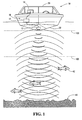
- the remotely located processor 14 may be mounted on a boat 18 in a wheelhouse 20 thereof, for example and the sonar transducer unit 12 may be secured to the hull 22 of the boat 18 or may be towed behind, for example.
- the processor 14 controls the sonar transducer unit 12 causing it to produce and receive sonar signals and send signals representing the sonar signals to the processor 14 for processing to produce a display image on the display 16, indicating underwater elements such as fish 42 or an ocean bottom 44, for example, that have reflected the sonar signals produced by the sonar transducer unit 12.
- the display image is produced by using the process and apparatus described herein to calculate illumination values for each pixel within a field of view represented by the display.
- the sonar transducer unit 12 includes a digital signal processor (DSP) 30 controlled by a program stored in an Erasable Programmable Read Only Memory (EPROM) 31.
- the DSP 30 is in communication with a communications interface 32, which in this embodiment includes a Universal Asynchronous Receiver Transmitter (UART) or Ethernet Network Interface Chip, for example.
- the communications interface 32 is in communication with the processor 14 shown in Figure 1 , through a cable 33 extending from the transducer unit 12 to the processor 14 and facilitates communications between the DSP 30 and the processor 14.
- the DSP 30 is operable to receive a "remote" command signal from the processor 14, the remote command signal containing depth range information. The DSP extracts this depth range information and produces one or more "local" command signals to control various components of the sonar transducer unit 12.
- the sonar transducer unit 12 includes a sonar signal source, referred to hereafter as a transmit transducer or sonar signal transducer 34.
- the transmit transducer 34 produces sonar signals in response to electrical input signals received from a transmit amplifier 36 which receives input signals from a transmit and mixing frequency numerically controlled oscillator (NCO) 38 controlled by a local command signal produced by the DSP 30.
- NCO numerically controlled oscillator
- the DSP 30 and transmit and mixing frequency NCO 38 cooperate to cause the transmit transducer 34 to produce a sonar signal burst of acoustic energy having a "ping length", the ping length being dependent upon the depth range of interest specified in the local command signal.
- the sonar signal burst of acoustic energy also has an acoustic frequency set by the transmit and mixing frequency NCO 38 in response to the local command.
- the acoustic frequency may be 320 kHz, for example, and in general, it may be any frequency that provides for suitable acoustic energy propagation in the medium (e.g., water in this embodiment) in which depth or distance is to be measured.
- the burst of acoustic energy propagates through the water and is reflected by elements in the water, such as fish 42 or the ocean bottom 44, for example, which cause a reflected acoustic pressure signal burst to be reflected back to the transducer unit 12.
- the transducer unit 12 receives the reflected acoustic signal burst at a plurality (m) of transducer elements which in this embodiment includes only two elements, to produce a plurality of received signals, generates a reference signal having a reference frequency dependent on a depth range of interest, heterodynes each of the received signals with the reference signal to produce respective beat signals having a beat frequency, samples each of the beat signals at a sampling frequency dependent on the beat frequency to produce sets of sample values, each set of sample values being associated with a corresponding transducer element, and makes each set of sample values available for processing.
- the transducer unit 12 includes a sonar signal receiver apparatus such as shown generally at 50 comprising transducer elements A and B arranged side by side on a linear axis 49 with a spacing 51 of about 3 mm between the transducer elements. Other spacings could be used.
- a sonar signal receiver apparatus such as shown generally at 50 comprising transducer elements A and B arranged side by side on a linear axis 49 with a spacing 51 of about 3 mm between the transducer elements. Other spacings could be used.
- the transducer elements A and B receive the reflected acoustic signal burst from any reflecting elements within the water.
- the transducer elements receive the reflected signal burst from a given reflecting element at different times due to the difference in distance between the given reflecting element and each transducer element as a result of the spacing 51 between the transducer elements.
- a reflected sound wave having the same amplitude-time properties is received at each transducer element A and B but appears to be shifted in time due to the differences in travel time of the reflected acoustic signal burst to reach respective transducer elements A and B.
- each of the transducer elements A and B has an associated signal conditioning stage as shown generally at 54, which, in this embodiment includes a pre-amplifier and time varying gain amplifier for producing a suitably strong amplified analog electrical signal representing the reflected acoustic signal received at the corresponding transducer element.
- the receiver apparatus 50 further includes a heterodyning component shown generally at 56 operable to heterodyne each of the amplified transducer element signals with a reference signal to produce respective modulated signals.
- the reference signal is produced by the transmit and mixing frequency NCO 38 which acts as a reference signal frequency generator to produce the reference signal in response to the local command signal received from the DSP 30.
- the local command is produced by the DSP 30 in response to depth range information in the remote command received from the processor 14.
- the reference signal has a reference frequency which is the sum of the acoustic frequency and a "delta" frequency. Delta frequencies and resulting reference frequencies for various depth ranges are shown in Figure 4 .
- the reference frequency generator NCO 38
- the heterodyning component 56 includes two signal mixers shown generally at 58 which multiply the reference signal with respective individual amplified transducer element signals to produce respective mixed signals.
- a reference signal at a reference frequency associated with a particular depth range is mixed (multiplied) with the signals produced by each transducer element, which have a frequency at the acoustic frequency (e.g., 320 kHz).
- the resulting modulated signals each have sum and difference components having frequencies f 1 + f 2 and f 1 - f 2 respectively, which preserve the relative phase of the received sound pressure from the different transducer elements.
- the difference component also referred to as a beat component contains the amplitude information of the original received signal and has a beat frequency corresponding to the delta frequency employed for the particular depth range of interest.
- the beat components associated with respective transducer elements A and B are used for further processing in this embodiment.
- the beat components are applied to respective cutoff frequency controlled low pass filters as shown generally at 60 to produce respective beat signals.
- These filters are controlled to have a common cutoff frequency set by a cutoff frequency control signal produced by a low pass and sampling frequency numerically controlled oscillator (NCO) 62 controlled by a local command produced by the DSP 30.
- the NCO 62 produces the cutoff frequency signal such that the cutoff frequency of the cutoff frequency controlled low pass filters is dependent upon the beat frequency as determined by the delta frequency set according to the depth range of interest, in response to the local command received from the DSP 30.
- the low pass filters 60 thus produce filtered beat signals associated with array elements A and B, respectively, having a frequency dependent on the reference frequency.
- a time-amplitude representation of acoustic pressure received at a given transducer element such as element (B), for example, is shown generally at 70.
- Amplitude is shown relative to a reference value of zero with positive amplitude values being to the right of the zero value and negative amplitude values being to the left of the zero value.
- the transducers would include antennas and the amplitude of a reflected electromagnetic wave received at an antenna could follow a similar trace.
- the transducer unit 12 further includes a sampling component 64 which, in this embodiment, includes the DSP 30 and a two-channel analog to digital converter which cooperates to individually simultaneously sample each of the beat signals to produce respective sets of time domain sample values, each set being associated with a respective transducer element A and B.
- the DSP 30 initiates sampling shortly after an acoustic burst is issued by the transmit transducer 34 and continues sampling until shortly after all reflected acoustic signals are expected to have been received, as determined by the depth range of interest.
- the sets of sample values are stored in memory 66 incorporated in the DSP 30.
- the DSP issues a local command to the low pass and sampling frequency NCO 62 which acts as a sampling signal frequency generator that generates a sampling signal for controlling the sampling component 64 to sample the filtered beat signals at a sampling frequency.
- the sampling frequency is set according to the depth range of interest and, more particularly, is set to be a multiple of the expected beat frequency of the beat signals, ultimately determined by the "delta" frequency. In this embodiment, the sampling frequency is set at 2.4615 times the delta frequency. Exemplary sampling frequencies for various depth ranges are shown in the table shown in Figure 4 .
- the sampling component 64 is controlled such that the same number of sample values is produced regardless of the depth range of interest.
- 500 sample values are included in each set of sample values, regardless of range.
- 2 sets of 500 samples are produced.
- the effect of producing the same number of samples regardless of the depth range of interest is that for greater depth ranges, the distance the sound travels between samples is greater than at lesser depth ranges. Fine resolution over long distances is usually not required and can exceed the resolution of the display and thus, a larger number of samples at a greater depth range is not required.
- sample points i.e. times at which samples are taken by the sampling component 64 of Figure 2
- the x's thus depict sample-defined positions along the waveform.
- a corresponding distance in cm for a 40 m-depth range of interest is shown for each sample point.
- a corresponding sample number S n is also shown.
- sample number 6 is associated with a distance of 47.7 cm from the transducer elements A and B.
- the programs in the EPROM 31 include program code for implementing a communications function to cause the DSP 30 to transmit to the processor 14, via the communications interface 32, the sets of sample values for further processing at the processor 14.
- These codes and the DSP 30 act as a communications component operable to communicate each set of sample values to the processor 14 for interpretation to control the illumination of pixels on the display 16 to ultimately produce a display image.
- a plurality of transducer elements may be employed.
- an array of sixteen transducer elements may be employed and a separate set of sample values may be produced and communicated to the processor 14 for each respective transducer element.
- at least two sets of samples from two separate, spaced apart transducers are required.
- the processor 14 may include a Personal Computer (PC) style computer, for example, of the type having a 2.8GHz Pentium IV processor chip, for example.
- PC Personal Computer
- Various computer implementations could be used, provided they have enough processing speed to perform the calculations described below sufficiently fast to avoid a noticeable delay in producing successive updates of a display image seen on the display 16.
- an exemplary processor circuit suitable to perform the operations described herein is shown at 72 in Figure 6 .
- the exemplary processor circuit includes a central processing unit (CPU) 74, program memory 76, random access memory 78 an input interface 80 and an output interface 82.
- CPU central processing unit
- the program memory 76 acts as a computer readable medium for storing program codes for directing the CPU, (hereinafter referred to as a processor) to carry out the functions described herein.
- the random access memory 78 may be used by the processor to store the sets of samples from each transducer element, for example.
- the input interface 80 is in communication with a user input device 84, which may include a keyboard, pointing device or other human interface.
- the input interface 80 and the output interface 82 are in communication with a communications unit 86 which is in communication with the sonar transducer unit 12 to permit the processor to send the above described remote command to the sonar transducer unit 12 and to permit the processor to receive the sets of sample values associated with respective transducers.
- the input interface 80 may include provisions such as a network interface 88 for receiving from a network, such as the Internet, computer readable signals encoded with codes operable to be stored in the program memory 76 for directing the processor to carry out one or more of the functional tasks described herein.
- a network such as the Internet
- computer readable signals encoded with codes operable to be stored in the program memory 76 for directing the processor to carry out one or more of the functional tasks described herein.
- the input interface 80 may be connected or connectable to a media reader 90 operable to read computer readable media that may provide codes operable to be stored in the program memory 76 for directing the processor to carry out one or more of the functional tasks described herein.
- the output interface 82 is in communication with the display 16 to control the display to produce an image representing objects beneath the boat.
- the codes stored in the program memory 76 direct the processor to carry out a process for producing illumination signals for use in controlling illumination of pixels on a display, in response to the sets of sample values associated with respective transducers.
- the process involves producing first and second beam signals in response to delayed channel signals associated with respective transducers.
- the delayed channel signals may be previously produced by the same processor or another processor in response to the sets of sample values associated with respective transducers and represent real and imaginary components of time domain signals associated with respective transducers, suitably delayed to focus a receive beam pattern of the transducers at a beam angle.
- the function shown in block 202 involves combining the delayed channel signals to produce only two beam signals.
- Each of the first and second beam signals includes separate real and imaginary component representations.
- Combining the delayed channel signals for respective transducers may be done by adjusting the amplitudes of the sample values of each set of samples, according to suitable delay values associated with a desired beam angle at which it is desired to focus the array and then for each sample time, adding the adjusted sample values to produce a combined sample value for that sample time.
- the combined sample values may then be scaled, as desired, into a workable range.
- Combining sets of sample values can be done symmetrically, such as by combining the delayed channel signals associated with the first eight transducers in a set of sixteen transducer elements, for example, to produce the first beam signal and then combining the sample values associated with the ninth through sixteenth transducers to produce the second beam signal.
- the sets of sample values associated with each transducer may be asymmetrically combined.
- the set of sample values associated with the first through fourth transducers may be combined to produce the first beam signal and the sets of sample values associated with the fifth through sixteenth transducers may be combined to produce the second beam signal, or vice versa.
- each beam signal represents a channel signal associated with a respective virtual transducer, since there is no single transducer with which the actual first and second beam signals are associated.
- the first and second beam signals represent received at a respective real or virtual transducer.
- the process then involves combining the real and imaginary components of the first and second beam signals, to produce a composite beam signal.
- the composite beam signal includes separate real and imaginary component representations.
- the process then involves performing a trigonometric expansion on normalized values of the real and imaginary component representations of the composite beam signal to produce a plurality of expanded values.
- the process then involves producing illumination signals in response to the expanded values, for illuminating pixels on the display.
- the broad process shown in Figure 7 may be used in the acoustic imaging system shown in Figure 1 , with suitable adaptations to facilitate use with a plurality of transducers, if desired, and with certain considerations for processing information for a plurality of beam angles at once.
- FIG. 8 An embodiment of the broad process adapted for use in the acoustic imaging system of Figure 1 , is shown generally at 100 in Figure 8 .
- the generic process shown in Figure 7 has been adapted to further include additional functions to adapt the process to the particular display used.
- the process applied to the acoustic imaging system in Figure 1 includes a first initialization step depicted generally at 96 in Figure 8 .
- Initialization is carried out by a block of program codes that directs the processor 72 shown in Figure 6 to retrieve initialization parameters from program memory 76.
- Initialization parameters may be stored in a file and retrieved by the processor on power up. These initialization parameters may be used by the processor to set color schemes for the display 16, for example, by creating a mapping between signal intensity and color. The color red for example may be used to identify signal portions of greater intensity or amplitude, while blue for example may be used to represent signal intensity or amplitude near zero.
- the initialization parameters may also be used to initialize any mathematical variable or arrays used for computations to follow.
- the processor may include routines (not shown), that cause it to receive user input from the user input device 84, or referring to Figure 2 , to communicate with the DSP 30 in the transducer unit 12, to acquire data indicating the spacing 51 between the transducer elements (e.g. 3 mm), the acoustic frequency (e.g. 320 kHz), the speed of sound in water (e.g. 1500 m/s), the sampling frequency used by the receiver (e.g. 9.375 kHz) and any other information that may be necessary.
- user input may be provided through the user input device 84 to indicate to the processor the dimensions or useable area of the display 16 in pixels (e.g. 640 x 480 ), for example, in which an image may be displayed.
- program codes may be provided to present menus on the display 16 to permit a user to select a depth range of interest.
- the user may select a depth range of 5, 10, 20 or 40 meters, for example, and referring to Figure 1 , may select a reference plane 103 such as a plane coincident with the linear axis 49, or a non-axis-coincident reference plane 105 at a depth below the plane coincident with the linear axis.
- the range may be set to 40 meters, for example and the reference plane may be set at 20 meters, for example, thus selecting an area of interest of between 20 and 40 meters depth.
- a mapping can be created to map the locations of pixels on the display to corresponding locations within the area of interest.
- pixel positions on the display are mapped to or associated with "pixel-defined positions" in the area of interest.
- the reference frequency, sample frequency and filter cutoff frequency to be used by the transducer unit may be determined from the table shown in Figure 4 , before any acoustic energy is emitted or received.
- an exemplary field of view is 102.75 degrees centered on the linear axis 49.
- the processor sets the color of every pixel associated with a location outside of the field of view to black, and only considers and performs calculations to determine illumination intensity for pixels at locations on the display 16 that have corresponding locations inside the field of view, in the area of interest.
- Block 102 directs the processor to produce delay signals in response to transducer spacing, angular frequency of wave energy received at the transducers, desired beam angle and speed of the wave energy in an area of a medium for which the image is to be produced.
- block 102 first directs the processor to define a plurality of beam angles and pre-calculate delay signals for each beam angle within the field of view.
- arbitrarily, 150 beam angles are defined.
- the above relation provides a suitable approximation for calculating delay values where it is assumed the sound wave impinging upon the transducer elements is a plane wave.
- Other geometric relations may be more suitable for calculating beam angles where the impinging sound wave is more spherical for example, i.e. at close range. For example, if a representation of a pixel position of interest can be obtained relative to the transducer elements, simple triangulation can be used to determine a corresponding beam angle for that pixel and each transducer element.
- pre-calculation of the range delay ST r for each beam angle results in 150 transducer-dependent phase values (ST r [k][m]), represented in units of radians, for each transducer element as depicted generally at 120.
- sine and cosine values are then produced for each beam angle, i.e., Sin (ST r [k][m]) and Cos (ST r [k][m]), to produce 150 pairs of Sine and Cosine values as shown at 124, for each of the first and second transducers A and B, for each beam angle.
- the sine and cosine values associated with the first transducer act as a first delay signal and the sine and cosine values associated with the second transducer act as a second delay signal.
- the first and second delay signals are pre-calculated before receiving or producing the first and second channel signals.
- the delay signals for each transducer may be pre-calculated by another processor and sent to the processor shown in Figure 6 , or they may be pre-calculated and stored in memory for use by the processor shown in Figure 6 .
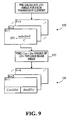
- block 104 directs the processor to acquire time samples from the transducers. This may involve causing the processor shown in Figure 6 to communicate with the transducer unit 12, to cause it to initiate the sampling process as described above to cause the transducer unit to send sets of samples from each transducer to the processor shown in Figure 6 . Representations of time samples are shown generally at 126 in Figure 10 A , for example.
- Block 106 then directs the processor to produce channel signals for respective transducers, in response to respective sets of time samples.
- the processor is directed to perform a Fourier Transform on each respective data set 126 to produce respective frequency domain representations of the sets of time samples and then to perform an inverse Fourier Transform on respective frequency domain representations to produce respective representations of synthesized waveforms representing time domain representations of the waveforms associated with respective transducers.
- the representations of the synthesized waveforms may be referred to as channel signals.
- Each synthesized waveform for each real or virtual transducer has the form: A t ⁇ cos ⁇ t
- the inverse Fourier Transform effectively provides sets of values 130 and 132 for each respective transducer, each set representing real and imaginary portions of its respective synthesized waveform at a plurality of sample points in time.
- the sets of values 130 and 132 thus represent a channel signal for corresponding transducers.
- the sample times of the Inverse Fourier Transform may be referred to as Fourier sample times and coincide with the sample times of the original waveforms.
- the processor may produce the channel signals in response to time samples from corresponding transducers or another processor may produce them and they may be received by the processor shown in Figure 6 and processed as described below, regardless of whether they are produced or received by the processor shown in Figure 6 .
- Channel signals are produced using the process described above in connection with blocks 126 and 106, for each transducer.
- block 108 directs the processor to produce the first and second delayed channel signals in response to the delay signals produced at block 102 and the channel signals produced at block 106.
- the transducers may be labeled A-P and real and imaginary components for the delayed channel signal associated with a respective transducer may be calculated using the relations shown above.
- the result is shown generally at 134 in Figure 10A where real and imaginary components of each delayed channel signal, for each beam angle are given for respective transducers A - P.
- a delayed channel signal comprising real and imaginary components for a plurality of time samples and for a plurality of beam angles is produced for each respective transducer.
- the delayed channel signals represent real and imaginary components of time domain signals associated with the transducers, suitably delayed to focus a receive beam pattern of the transducers at a beam angle.
- the transducers are then divided into two groups and the delayed channel signals of each group are combined to produce first and second beam signals respectively.
- the first and second beam signals are produced in response to the delayed channel signals.
- the transducers need not be grouped symmetrically.
- the first four delayed channel signals may be combined as described above to produce the first beam signal and the fifth through sixteenth delayed channel signals may be combined to produce the second beam signal or other combinations of channel signals may be used.
- each composite beam signal including separate real and imaginary component representations as shown at 138.
- the composite beam signal is comprised of a plurality of magnitude values produced according to the relation below in which the value ⁇ , represents the amplitude value of the composite beam signal at sample point n, at the given beam angle.
- ⁇ k , n ⁇ ⁇ R k , n ⁇ ⁇ ⁇ R k , n + ⁇ ⁇ I k , n ⁇ ⁇ ⁇ I k , n 2 + ⁇ ⁇ I k , n ⁇ ⁇ ⁇ R k , n - ⁇ ⁇ I k , n ⁇ ⁇ ⁇ R k , n 2
- k 1 to 150 beam angles
- n 1 to 500 sample points
- Block 112 then directs the processor to normalize the composite beam signal to produce a normalized composite beam signal for each beam angle.
- the processor is directed to calculate a real part of the product of the first beam signal and the complex conjugate of the second beam signal and then scale the real part by the magnitude value.
- the normalized composite beam signal is thus comprised of a set of normalized composite values.
- the sets of normalized composite values are shown generally at 140 in Figure 10B .
- block 114 then directs the processor to perform a trigonometric expansion on each normalized composite value of each set of normalized composite values to produce expanded composite values.
- z may be 17, for example.
- Each of these expanded composite values for each angle will be near z if the signals of beams of the transducers are in phase, and will sum to near 1 otherwise.
- performing a trigonometric expansion may comprise performing a sum of Chebyshev polynomials on respective values of the composite beam signal.
- the result is a set of amplitude values for each beam angle.
- block 118 directs the processor to map the sets of amplitude values associated with respective beam angles to corresponding rays on the display, and to use the amplitude values in a given set of amplitude values control the illumination intensity of respective pixels along the ray.
- the display may include a rectangular pixel array of 640 by 480 pixels, for example. Rays, one of which is designated 152 may be defined to emanate from a common point such as shown at 154, which corresponds to the centerpoint between the transducers A and B shown in Figures 2 and 3 . In Figure 11 , six rays are shown, each at a different angle 1 - 6 corresponding to a respective beam angle. From the initialization procedures performed by block 96 in Figure 7 and from the knowledge of the field of view and number of radians per sample determined by blocks 98 and 99 in Figure 7 , the sample time is known and thus so is the sample distance.
- the sample distance may be related to pixels on the display by mapping the sample distance to a pixel distance representing a distance on the display, from the common point 154.
- the mapping depends upon the scale of the display.
- the representative waveform shown in Figure 5 may be considered to lie on one of the rays shown in Figure 11 such that the zero time position is coincident with the common point 154 and a maximum time point is coincident with the 480 th pixel along the ray.
- the representative waveform is mapped onto the ray on the display 16.
- sampling frequency 9.375 KHz
- a plurality of pixel-defined positions p may be marked on the time-amplitude representation as shown.
- the pixels on the display viewing area will generally represent amplitude at different times t than the times x associated with samples.
- the sample distance can be calculated and the pixel nearest the sample distance can be illuminated with the corresponding amplitude value.
- the nearest pixel may be found by using the sample distance and beam angle to find rectangular coordinates for the nearest pixel.
- the processor simply steps through the set of amplitude values for a given beam angle, calculates the corresponding sample distance from the current sample number, finds the nearest pixel and uses the associated amplitude value to specify a pixel illumination intensity and/or color to illuminate the pixel.
- the pixels along rays associated with beam angles are successively illuminated and the pixels along rays corresponding to successive beam angles illuminated, thereby creating an overall image, representing features that reflect sound in water.
- the process may be repeated several times per second for all the beam angles, thereby updating the overall image several times per second and providing a real-time image.
- the trigonometric expansion conducted at block 206 in Figure 7 and at block 114 in Figures 8 and 10B serves to sharpen the focus of the transducers to produce an effective beam width greater than would be achieved without trigonometric expansion.
- FIG 12 representation of beam width with and without the trigonometric expansion is shown generally at 156.
- a trace 158 shown in broken outline, depicts beam width in a system of the type shown without the use of the trigonometric expansion step 114 shown in Figures 8 and 10B .
- trace 158 shows beam width for a system in which the normalized composite values are simply scaled to produce the amplitude values used to illuminate pixels on the display.
- a trace 160 depicts beam width when the trigonometric expansion step 114 is included in the process and shows a significant narrowing of beam width beginning at about 40 degrees off-center of the beam.
- the use of the trigonometric expansion step has the effect of causing the transducer array to act as though it were an array of a greater number of transducers.
- Increasing the degree of the trigonometric expansion greater than the 17 th order as in the embodiment described, has the effect of further focusing the beam, creating the effect of a greater number of transducers.
- the method described above involves the use of a Fourier Transform performed on time samples from a given transducer, followed by an inverse Fourier Transform, which accurately produces real and imaginary components of the channel signal for that transducer. These real and imaginary components are used in subsequent calculations and ultimately contribute to the production of the normalized composite values that are used in the trigonometric expansion. Without accurately produced real and imaginary components of the channel signals, such as would be the case with most analog systems, the signal to noise ratio of the channel signals and their components would begin to swamp the higher order terms of the trigonometric expansion, thereby diminishing the value of the higher order terms, rendering them useless and effectively limiting the benefit of the trigonometric expansion.
Landscapes
- Engineering & Computer Science (AREA)
- Radar, Positioning & Navigation (AREA)
- Remote Sensing (AREA)
- Physics & Mathematics (AREA)
- Computer Networks & Wireless Communication (AREA)
- General Physics & Mathematics (AREA)
- Acoustics & Sound (AREA)
- Measurement Of Velocity Or Position Using Acoustic Or Ultrasonic Waves (AREA)
Claims (46)
- Prozess zum Erzeugen von Signalen zum Steuern einer Anzeige zum Erzeugen eines Bildes in einem Bildgabesystem unter Verwendung mehrerer Messwandler, wobei der Prozess Folgendes umfasst:Erzeugen eines ersten und eines zweiten Strahlsignals in Reaktion auf verzögerte Kanalsignale, die jeweiligen Messwandlern zugeordnet sind, wobei die verzögerten Kanalsignale reale und imaginäre Komponenten von Zeitbereichssignalen darstellen, die jeweiligen Messwandlern zugeordnet sind, die auf geeignete Weise verzögert werden, um ein Empfangsstrahlmuster der Messwandler in einem Strahlwinkel zu fokussieren, wobei sowohl das erste als auch das zweite Strahlsignal separate reale und imaginäre Komponentendarstellungen enthalten;Kombinieren der realen und imaginären Komponentendarstellungen des ersten und des zweiten Strahlsignals, um ein zusammengesetztes Strahlsignal zu erzeugen, wobei das zusammengesetzte Strahlsignal separate reale und imaginäre Komponentendarstellungen enthält;Ausführen einer trigonometrischen Entwicklung an normalisierten Werten der realen und imaginären Komponentendarstellungen des zusammengesetztes Strahlsignals, um mehrere entwickelte Werte zu erzeugen; undErzeugen von Beleuchtungssignalen in Reaktion auf die entwickelten Werte zum Beleuchten von Pixeln auf der Anzeige.
- Prozess nach Anspruch 1, der des Weiteren das Empfangen der verzögerten Kanalsignale umfasst.
- Prozess nach Anspruch 1, der des Weiteren das Erzeugen der verzögerten Kanalsignale umfasst.
- Prozess nach Anspruch 3, wobei das Erzeugen der verzögerten Kanalsignale das Erzeugen der verzögerten Kanalsignale in Reaktion auf Kanalsignale und Verzögerungssignale, die den jeweiligen Messwandlern zugeordnet sind, umfasst,
wobei jedes Kanalsignal ein Signal darstellt, das in einem entsprechenden Messwandler empfangen wird, und separate reale und imaginäre Komponentendarstellungen enthält; und
wobei die Verzögerungssignale separate Kosinus- und Sinusverzögerungskomponenten einer Verzögerung enthalten, die von einem gewünschten Strahlwinkel abhängig ist, in dem die Messwandler fokussiert werden sollen;
wobei jedes der verzögerten Kanalsignale separate reale und imaginäre Komponentendarstellungen enthält. - Prozess nach Anspruch 4, der des Weiteren das Empfangen der Kanalsignale umfasst.
- Prozess nach Anspruch 4, der des Weiteren das Erzeugen der Kanalsignale umfasst.
- Prozess nach Anspruch 6, wobei das Erzeugen der Kanalsignale Folgendes umfasst: Erzeugen von Frequenzbereichsdarstellungen jeweiliger zeitlich abgetasteter Darstellungen jeweiliger Signale, die in jeweiligen Messwandlern empfangen werden, und Erzeugen von Zeitbereichsdarstellungen der jeweiligen Signale in Reaktion auf die Frequenzbereichsdarstellungen, wobei die Zeitbereichsdarstellungen reale und imaginäre Komponenten umfassen.
- Prozess nach Anspruch 4, der des Weiteren das Empfangen der Verzögerungssignale umfasst.
- Prozess nach Anspruch 8, der des Weiteren das Empfangen der Kanalsignale umfasst, und wobei die Verzögerungssignale empfangen werden, bevor die Kanalsignale empfangen werden.
- Prozess nach Anspruch 4, der des Weiteren das Erzeugen der Verzögerungssignale umfasst.
- Prozess nach Anspruch 10, der des Weiteren das Empfangen der Kanalsignale umfasst, und wobei die Verzögerungssignale erzeugt werden, bevor die Kanalsignale empfangen werden.
- Prozess nach Anspruch 10, wobei das Erzeugen der Verzögerungssignale das Erzeugen der Verzögerungssignale in Reaktion auf eine Messwandlerbeabstandung, eine Winkelfrequenz einer in den Messwandlern empfangenen Wellenenergie, einen gewünschten Strahlwinkel und eine Geschwindigkeit der Wellenenergie in einem Bereich eines Mediums, für den das Bild erzeugt werden soll, umfasst.
- Prozess nach Anspruch 1, der des Weiteren Folgendes umfasst:Erzeugen eines normalisierten zusammengesetzten Strahlsignals, das mehrere normalisierte Werte umfasst, in Reaktion auf die realen und imaginären Komponentendarstellungen des zusammengesetzten Strahlsignals; und für jeden der normalisierten Werte: Berechnen eines realen Teils des Produkts des ersten Strahlsignals und einer Komplexkonjugierten des zweiten Strahlsignals.
- Prozess nach Anspruch 13, wobei das Erzeugen eines normalisierten zusammengesetzten Strahlsignals das Skalieren des realen Teils eines Produkts des ersten Strahlsignals und einer Komplexkonjugierten des zweiten Strahlsignals um einen Größenordnungswert umfasst.
- Prozess nach Anspruch 14, der des Weiteren das Erzeugen des Größenordnungswertes in Reaktion auf die realen und imaginären Komponenten des ersten und des zweiten Strahlsignals umfasst.
- Prozess nach Anspruch 1, wobei das Ausführen der trigonometrischen Entwicklung das Ausführen einer Reihenentwicklung an jedem der normalisierten Werte umfasst.
- Prozess nach Anspruch 1, wobei das Ausführen der trigonometrischen Entwicklung das Ausführen einer Summe Tschebyscheffscher Polynome an jedem der normalisierten Werte umfasst.
- Prozess nach Anspruch 1, der des Weiteren das Beleuchten von Pixeln auf der Anzeige in Reaktion auf die Beleuchtungssignale umfasst.
- Prozess zum Erzeugen von Signalen zum Steuern einer Anzeige zum Erzeugen eines Bildes in einem Bildgabesystem, wobei der Prozess das Durchführen des Prozesses nach Anspruch 1 für jeden von mehreren Strahlwinkeln zum Erzeugen einer Menge von Beleuchtungssignalen für jeden der Strahlwinkel umfasst.
- Prozess nach Anspruch 19, der des Weiteren das Definieren der mehreren Strahlwinkel umfasst.
- Prozess nach Anspruch 19, der des Weiteren das Abbilden jeweiliger Mengen von Beleuchtungswerten auf jeweilige Strahlen von Pixeln auf der Anzeige umfasst, wobei jeder der Strahlen einem jeweiligen Strahlwinkel entspricht, wobei die Beleuchtungssignale in der Lage sind zu veranlassen, dass Pixel entlang eines bestimmtes Strahls in Reaktion auf entsprechende Beleuchtungswerte beleuchtet werden.
- Computerlesbares Medium, das mit Instruktionen codiert ist, um einen Prozessor anzuweisen, den Prozess nach Anspruch 1 auszuführen.
- Computerlesbares Signal, das mit Instruktionen codiert ist, um einen Prozessor anzuweisen, den Prozess nach Anspruch 1 auszuführen.
- Vorrichtung zum Erzeugen von Signalen zum Steuern einer Anzeige zum Erzeugen eines Bildes in einem Bildgabesystem unter Verwendung mehrerer Messwandler, wobei die Vorrichtung Folgendes umfasst:ein Mittel zum Erzeugen eines ersten und eines zweiten Strahlsignals in Reaktion auf verzögerte Kanalsignale, die jeweiligen Messwandlern zugeordnet sind, wobei die verzögerten Kanalsignale reale und imaginäre Komponenten von Zeitbereichssignalen darstellen, die jeweiligen Messwandlern zugeordnet sind, die auf geeignete Weise verzögert werden, um ein Empfangsstrahlmuster der Messwandler in einem Strahlwinkel zu fokussieren, wobei sowohl das erste als auch das zweite Strahlsignal separate reale und imaginäre Komponentendarstellungen enthalten;ein Mittel zum Kombinieren der realen und imaginären Komponentendarstellungen des ersten und des zweiten Strahlsignals, um ein zusammengesetztes Strahlsignal zu erzeugen, wobei das zusammengesetzte Strahlsignal separate reale und imaginäre Komponentendarstellungen enthält;ein Mittel zum Ausführen einer trigonometrischen Entwicklung an normalisierten Werten der realen und imaginären Komponentendarstellungen des zusammengesetztes Strahlsignals, um mehrere entwickelte Werte zu erzeugen; undein Mittel zum Erzeugen von Beleuchtungssignalen in Reaktion auf die entwickelten Werte, wobei die Beleuchtungssignale durch die Anzeige zum Beleuchten von Pixeln auf der Anzeige empfangen werden können.
- Vorrichtung nach Anspruch 24, die des Weiteren ein Mittel zum Empfangen der verzögerten Kanalsignale umfasst.
- Vorrichtung nach Anspruch 24, die des Weiteren ein Mittel zum Erzeugen der verzögerten Kanalsignale umfasst.
- Vorrichtung nach Anspruch 26, wobei das Mittel zum Erzeugen der verzögerten Kanalsignale ein Mittel zum Erzeugen der verzögerten Kanalsignale in Reaktion auf Kanalsignale und Verzögerungssignale, die den Messwandlern zugeordnet sind, umfasst,
wobei jedes Kanalsignal ein Signal darstellt, das in einem entsprechenden Messwandler empfangen wird, und separate reale und imaginäre Komponentendarstellungen enthält; und
wobei die Verzögerungssignale separate Kosinus- und Sinusverzögerungskomponenten einer Verzögerung enthalten, die von einem gewünschten Strahlwinkel abhängig ist, in dem die Messwandler fokussiert werden sollen;
wobei jedes der verzögerten Kanalsignale separate reale und imaginäre Komponentendarstellungen enthält. - Vorrichtung nach Anspruch 27, die des Weiteren ein Mittel zum Empfangen der Kanalsignale umfasst.
- Vorrichtung nach Anspruch 27, die des Weiteren ein Mittel zum Erzeugen der Kanalsignale umfasst.
- Vorrichtung nach Anspruch 29, wobei das Mittel zum Erzeugen der Kanalsignale Folgendes umfasst:ein Mittel zum Erzeugen von Frequenzbereichsdarstellungen jeweiliger zeitlich abgetasteter Darstellungen jeweiliger Signale, die in jeweiligen Messwandlern empfangen werden; undein Mittel zum Erzeugen von Zeitbereichsdarstellungen der jeweiligen Signale in Reaktion auf die Frequenzbereichsdarstellungen,wobei die Zeitbereichsdarstellungen reale und imaginäre Komponentendarstellungen umfassen.
- Vorrichtung nach Anspruch 27, die des Weiteren ein Mittel zum Empfangen der Verzögerungssignale umfasst.
- Vorrichtung nach Anspruch 31, die des Weiteren ein Mittel zum Empfangen der Kanalsignale umfasst, und wobei die Verzögerungssignale empfangen werden, bevor die Kanalsignale empfangen werden.
- Vorrichtung nach Anspruch 27, die des Weiteren ein Mittel zum Erzeugen der Verzögerungssignale umfasst.
- Vorrichtung nach Anspruch 33, die des Weiteren ein Mittel zum Empfangen der Kanalsignale umfasst, und wobei die Verzögerungssignale erzeugt werden, bevor die Kanalsignale empfangen werden.
- Vorrichtung nach Anspruch 33, wobei das Mittel zum Erzeugen der Verzögerungssignale ein Mittel zum Erzeugen der Verzögerungssignale in Reaktion auf eine Messwandlerbeabstandung, eine Winkelfrequenz einer in den Messwandlern empfangenen Wellenenergie, einen gewünschten Strahlwinkel und eine Geschwindigkeit der Wellenenergie in einem Bereich eines Mediums, für den das Bild erzeugt werden soll, umfasst.
- Vorrichtung nach Anspruch 24, die des Weiteren ein Mittel zum Erzeugen eines normalisierten zusammengesetzten Strahlsignals, das mehrere normalisierte Werte umfasst, in Reaktion auf die realen und imaginären Komponentendarstellungen des zusammengesetzten Strahlsignals umfasst, wobei das Mittel zum Erzeugen eines normalisierten zusammengesetzten Strahlsignals ein Mittel umfasst, um für jeden der normalisierten Werte einen realen Teil des Produkts des ersten Strahlsignals und einer Komplexkonjugierten des zweiten Strahlsignals zu berechnen.
- Vorrichtung nach Anspruch 36, wobei das Mittel zum Normalisieren ein Mittel zum Skalieren des realen Teils eines Produkts des ersten Strahlsignals und der Komplexkonjugierten des zweiten Strahlsignals um einen Größenordnungswert umfasst.
- Vorrichtung nach Anspruch 37, die des Weiteren ein Mittel zum Erzeugen des Größenordnungswertes in Reaktion auf die realen und imaginären Komponenten des ersten und des zweiten Strahlsignals umfasst.
- Vorrichtung nach Anspruch 24, wobei das Mittel zum Ausführen der trigonometrischen Entwicklung ein Mittel zum Ausführen einer Reihenentwicklung an jedem der normalisierten Werte umfasst.
- Vorrichtung nach Anspruch 24, wobei das Mittel zum Ausführen der trigonometrischen Entwicklung ein Mittel zum Ausführen einer Summe Tschebyscheffscher Polynome an jedem der normalisierten Werte umfasst.
- Vorrichtung nach Anspruch 24, die des Weiteren ein Mittel zum Beleuchten von Pixeln auf der Anzeige in Reaktion auf die entwickelten Werte umfasst.
- Vorrichtung nach Anspruch 24, die des Weiteren ein Mittel umfasst, um die Vorrichtung zum Erzeugen einer Menge von Beleuchtungssignalen für mehrere der Strahlwinkel zu veranlassen.
- Vorrichtung nach Anspruch 42, die des Weiteren ein Mittel zum Definieren der mehreren Strahlwinkel umfasst.
- Vorrichtung nach Anspruch 42, die des Weiteren ein Mittel zum Abbilden jeweiliger Mengen von Beleuchtungswerten auf jeweilige Strahlen von Pixeln auf der Anzeige umfasst, wobei jeder der Strahlen einem jeweiligen Strahlwinkel entspricht, wobei die Beleuchtungssignale in der Lage sind zu veranlassen, dass Pixel entlang eines bestimmtes Strahls in Reaktion auf entsprechende Beleuchtungswerte beleuchtet werden.
- Vorrichtung nach Anspruch 24, die Folgendes umfasst:Speicher zum Speichern von Signalen, die jeweiligen Messwandlern zugeordnet sind; undwobei das Mittel zum Erzeugen, das Mittel zum Kombinieren und das Mittel zum Ausführen in einem Prozessor implementiert sind, der mit dem Speicher kommuniziert.
- Vorrichtung nach Anspruch 45, die des Weiteren einen mit dem Prozessor wirkverbundenen Eingang zum Empfangen der verzögerten Kanalsignale umfasst.
Applications Claiming Priority (3)
| Application Number | Priority Date | Filing Date | Title |
|---|---|---|---|
| US10/891,655 US7212466B2 (en) | 2004-07-15 | 2004-07-15 | Producing amplitude values for controlling pixel illumination on a sonar display |
| US11/034,628 US7450470B2 (en) | 2004-07-15 | 2005-01-12 | High resolution images from reflected wave energy |
| PCT/CA2005/001081 WO2006005180A1 (en) | 2004-07-15 | 2005-07-12 | High resolution images from reflected wave energy |
Publications (3)
| Publication Number | Publication Date |
|---|---|
| EP1774360A1 EP1774360A1 (de) | 2007-04-18 |
| EP1774360A4 EP1774360A4 (de) | 2010-03-17 |
| EP1774360B1 true EP1774360B1 (de) | 2010-11-10 |
Family
ID=35783475
Family Applications (1)
| Application Number | Title | Priority Date | Filing Date |
|---|---|---|---|
| EP05763489A Expired - Lifetime EP1774360B1 (de) | 2004-07-15 | 2005-07-12 | Hochauflösende bilder aus reflexionswellenenergie |
Country Status (3)
| Country | Link |
|---|---|
| EP (1) | EP1774360B1 (de) |
| CA (2) | CA2573960C (de) |
| WO (2) | WO2006005179A1 (de) |
Family Cites Families (3)
| Publication number | Priority date | Publication date | Assignee | Title |
|---|---|---|---|---|
| JPS5444375A (en) * | 1977-09-14 | 1979-04-07 | Oki Electric Ind Co Ltd | Ultrasonic wave reflection system |
| JPS6282379A (ja) * | 1985-10-07 | 1987-04-15 | Nec Corp | ソ−ナ−信号表示方式 |
| WO1997004334A1 (en) * | 1995-07-18 | 1997-02-06 | Lowrance Electronics, Inc. | Integrated sonar and mapping system and associated method |
-
2005
- 2005-06-12 CA CA2573960A patent/CA2573960C/en not_active Expired - Fee Related
- 2005-06-12 WO PCT/CA2005/001079 patent/WO2006005179A1/en not_active Ceased
- 2005-07-12 EP EP05763489A patent/EP1774360B1/de not_active Expired - Lifetime
- 2005-07-12 WO PCT/CA2005/001081 patent/WO2006005180A1/en not_active Ceased
- 2005-07-12 CA CA2573970A patent/CA2573970C/en not_active Expired - Fee Related
Also Published As
| Publication number | Publication date |
|---|---|
| CA2573960C (en) | 2014-04-08 |
| WO2006005180A1 (en) | 2006-01-19 |
| EP1774360A1 (de) | 2007-04-18 |
| WO2006005179A1 (en) | 2006-01-19 |
| CA2573960A1 (en) | 2006-01-19 |
| CA2573970A1 (en) | 2006-01-19 |
| EP1774360A4 (de) | 2010-03-17 |
| CA2573970C (en) | 2013-10-29 |
Similar Documents
| Publication | Publication Date | Title |
|---|---|---|
| US7450470B2 (en) | High resolution images from reflected wave energy | |
| US6373970B1 (en) | Image registration using fourier phase matching | |
| US5841889A (en) | Ultrasound image texture control using adaptive speckle control algorithm | |
| EP1060413B1 (de) | Bestimmung des doppler-winkels in ultraschall farbströmung | |
| US5230340A (en) | Ultrasound imaging system with improved dynamic focusing | |
| US5235982A (en) | Dynamic transmit focusing of a steered ultrasonic beam | |
| US4237737A (en) | Ultrasonic imaging system | |
| US6130641A (en) | Imaging methods and apparatus using model-based array signal processing | |
| US5142649A (en) | Ultrasonic imaging system with multiple, dynamically focused transmit beams | |
| US4207620A (en) | Oceanographic mapping system | |
| JP4620261B2 (ja) | 高次の非線形成分による超音波撮像 | |
| US5349525A (en) | Color flow imaging system utilizing a frequency domain wall filter | |
| US5121364A (en) | Time frequency control filter for an ultrasonic imaging system | |
| JP2002534184A (ja) | コヒーレンス・イメージングのための方法および装置 | |
| JPH07503551A (ja) | 時間領域で適応可能な障壁フィルタを用いたカラー・フロー作像システム | |
| JPH0661333B2 (ja) | 流動する反射体の大きさ及び方向の表示を求める方法及びコヒーレント作像システム | |
| US6423004B1 (en) | Real-time ultrasound spatial compounding using multiple angles of view | |
| US5476098A (en) | Partially coherent imaging for large-aperture phased arrays | |
| US6740034B2 (en) | Three-dimensional ultrasound imaging system for performing receive-focusing at voxels corresponding to display pixels | |
| US6048313A (en) | Method and apparatus for fractal-based enhancement of ultrasound imaging | |
| EP1774360B1 (de) | Hochauflösende bilder aus reflexionswellenenergie | |
| EP0486096B1 (de) | Unterdrückung des Überfaltungsartefaktes in Puls-Dopplersystemen | |
| HK1102141B (en) | High resolution images from reflected wave energy | |
| JP3528580B2 (ja) | 物体計測装置 | |
| WO2011058527A1 (en) | Method and apparatus for processing sonar signals |
Legal Events
| Date | Code | Title | Description |
|---|---|---|---|
| PUAI | Public reference made under article 153(3) epc to a published international application that has entered the european phase |
Free format text: ORIGINAL CODE: 0009012 |
|
| 17P | Request for examination filed |
Effective date: 20070213 |
|
| AK | Designated contracting states |
Kind code of ref document: A1 Designated state(s): AT BE BG CH CY CZ DE DK EE ES FI FR GB GR HU IE IS IT LI LT LU LV MC NL PL PT RO SE SI SK TR |
|
| DAX | Request for extension of the european patent (deleted) | ||
| REG | Reference to a national code |
Ref country code: HK Ref legal event code: DE Ref document number: 1102141 Country of ref document: HK |
|
| A4 | Supplementary search report drawn up and despatched |
Effective date: 20100217 |
|
| GRAP | Despatch of communication of intention to grant a patent |
Free format text: ORIGINAL CODE: EPIDOSNIGR1 |
|
| RIC1 | Information provided on ipc code assigned before grant |
Ipc: G01S 13/89 20060101ALI20100504BHEP Ipc: G01S 7/04 20060101AFI20100504BHEP Ipc: G09G 5/10 20060101ALI20100504BHEP |
|
| GRAS | Grant fee paid |
Free format text: ORIGINAL CODE: EPIDOSNIGR3 |
|
| GRAA | (expected) grant |
Free format text: ORIGINAL CODE: 0009210 |
|
| AK | Designated contracting states |
Kind code of ref document: B1 Designated state(s): AT BE BG CH CY CZ DE DK EE ES FI FR GB GR HU IE IS IT LI LT LU LV MC NL PL PT RO SE SI SK TR |
|
| REG | Reference to a national code |
Ref country code: GB Ref legal event code: FG4D |
|
| REG | Reference to a national code |
Ref country code: CH Ref legal event code: EP |
|
| REG | Reference to a national code |
Ref country code: IE Ref legal event code: FG4D |
|
| REF | Corresponds to: |
Ref document number: 602005024691 Country of ref document: DE Date of ref document: 20101223 Kind code of ref document: P |
|
| REG | Reference to a national code |
Ref country code: NL Ref legal event code: VDEP Effective date: 20101110 |
|
| LTIE | Lt: invalidation of european patent or patent extension |
Effective date: 20101110 |
|
| PG25 | Lapsed in a contracting state [announced via postgrant information from national office to epo] |
Ref country code: LT Free format text: LAPSE BECAUSE OF FAILURE TO SUBMIT A TRANSLATION OF THE DESCRIPTION OR TO PAY THE FEE WITHIN THE PRESCRIBED TIME-LIMIT Effective date: 20101110 |
|
| PG25 | Lapsed in a contracting state [announced via postgrant information from national office to epo] |
Ref country code: IS Free format text: LAPSE BECAUSE OF FAILURE TO SUBMIT A TRANSLATION OF THE DESCRIPTION OR TO PAY THE FEE WITHIN THE PRESCRIBED TIME-LIMIT Effective date: 20110310 Ref country code: NL Free format text: LAPSE BECAUSE OF FAILURE TO SUBMIT A TRANSLATION OF THE DESCRIPTION OR TO PAY THE FEE WITHIN THE PRESCRIBED TIME-LIMIT Effective date: 20101110 Ref country code: BG Free format text: LAPSE BECAUSE OF FAILURE TO SUBMIT A TRANSLATION OF THE DESCRIPTION OR TO PAY THE FEE WITHIN THE PRESCRIBED TIME-LIMIT Effective date: 20110210 Ref country code: CY Free format text: LAPSE BECAUSE OF FAILURE TO SUBMIT A TRANSLATION OF THE DESCRIPTION OR TO PAY THE FEE WITHIN THE PRESCRIBED TIME-LIMIT Effective date: 20101110 Ref country code: AT Free format text: LAPSE BECAUSE OF FAILURE TO SUBMIT A TRANSLATION OF THE DESCRIPTION OR TO PAY THE FEE WITHIN THE PRESCRIBED TIME-LIMIT Effective date: 20101110 Ref country code: LV Free format text: LAPSE BECAUSE OF FAILURE TO SUBMIT A TRANSLATION OF THE DESCRIPTION OR TO PAY THE FEE WITHIN THE PRESCRIBED TIME-LIMIT Effective date: 20101110 Ref country code: FI Free format text: LAPSE BECAUSE OF FAILURE TO SUBMIT A TRANSLATION OF THE DESCRIPTION OR TO PAY THE FEE WITHIN THE PRESCRIBED TIME-LIMIT Effective date: 20101110 Ref country code: SE Free format text: LAPSE BECAUSE OF FAILURE TO SUBMIT A TRANSLATION OF THE DESCRIPTION OR TO PAY THE FEE WITHIN THE PRESCRIBED TIME-LIMIT Effective date: 20101110 Ref country code: PT Free format text: LAPSE BECAUSE OF FAILURE TO SUBMIT A TRANSLATION OF THE DESCRIPTION OR TO PAY THE FEE WITHIN THE PRESCRIBED TIME-LIMIT Effective date: 20110310 Ref country code: SI Free format text: LAPSE BECAUSE OF FAILURE TO SUBMIT A TRANSLATION OF THE DESCRIPTION OR TO PAY THE FEE WITHIN THE PRESCRIBED TIME-LIMIT Effective date: 20101110 |
|
| PG25 | Lapsed in a contracting state [announced via postgrant information from national office to epo] |
Ref country code: GR Free format text: LAPSE BECAUSE OF FAILURE TO SUBMIT A TRANSLATION OF THE DESCRIPTION OR TO PAY THE FEE WITHIN THE PRESCRIBED TIME-LIMIT Effective date: 20110211 |
|
| REG | Reference to a national code |
Ref country code: HK Ref legal event code: GR Ref document number: 1102141 Country of ref document: HK |
|
| PG25 | Lapsed in a contracting state [announced via postgrant information from national office to epo] |
Ref country code: EE Free format text: LAPSE BECAUSE OF FAILURE TO SUBMIT A TRANSLATION OF THE DESCRIPTION OR TO PAY THE FEE WITHIN THE PRESCRIBED TIME-LIMIT Effective date: 20101110 Ref country code: ES Free format text: LAPSE BECAUSE OF FAILURE TO SUBMIT A TRANSLATION OF THE DESCRIPTION OR TO PAY THE FEE WITHIN THE PRESCRIBED TIME-LIMIT Effective date: 20110221 Ref country code: BE Free format text: LAPSE BECAUSE OF FAILURE TO SUBMIT A TRANSLATION OF THE DESCRIPTION OR TO PAY THE FEE WITHIN THE PRESCRIBED TIME-LIMIT Effective date: 20101110 Ref country code: CZ Free format text: LAPSE BECAUSE OF FAILURE TO SUBMIT A TRANSLATION OF THE DESCRIPTION OR TO PAY THE FEE WITHIN THE PRESCRIBED TIME-LIMIT Effective date: 20101110 |
|
| PG25 | Lapsed in a contracting state [announced via postgrant information from national office to epo] |
Ref country code: PL Free format text: LAPSE BECAUSE OF FAILURE TO SUBMIT A TRANSLATION OF THE DESCRIPTION OR TO PAY THE FEE WITHIN THE PRESCRIBED TIME-LIMIT Effective date: 20101110 Ref country code: RO Free format text: LAPSE BECAUSE OF FAILURE TO SUBMIT A TRANSLATION OF THE DESCRIPTION OR TO PAY THE FEE WITHIN THE PRESCRIBED TIME-LIMIT Effective date: 20101110 Ref country code: DK Free format text: LAPSE BECAUSE OF FAILURE TO SUBMIT A TRANSLATION OF THE DESCRIPTION OR TO PAY THE FEE WITHIN THE PRESCRIBED TIME-LIMIT Effective date: 20101110 Ref country code: SK Free format text: LAPSE BECAUSE OF FAILURE TO SUBMIT A TRANSLATION OF THE DESCRIPTION OR TO PAY THE FEE WITHIN THE PRESCRIBED TIME-LIMIT Effective date: 20101110 |
|
| PLBE | No opposition filed within time limit |
Free format text: ORIGINAL CODE: 0009261 |
|
| STAA | Information on the status of an ep patent application or granted ep patent |
Free format text: STATUS: NO OPPOSITION FILED WITHIN TIME LIMIT |
|
| 26N | No opposition filed |
Effective date: 20110811 |
|
| REG | Reference to a national code |
Ref country code: DE Ref legal event code: R097 Ref document number: 602005024691 Country of ref document: DE Effective date: 20110811 |
|
| PG25 | Lapsed in a contracting state [announced via postgrant information from national office to epo] |
Ref country code: IT Free format text: LAPSE BECAUSE OF FAILURE TO SUBMIT A TRANSLATION OF THE DESCRIPTION OR TO PAY THE FEE WITHIN THE PRESCRIBED TIME-LIMIT Effective date: 20101110 |
|
| PG25 | Lapsed in a contracting state [announced via postgrant information from national office to epo] |
Ref country code: MC Free format text: LAPSE BECAUSE OF NON-PAYMENT OF DUE FEES Effective date: 20110731 |
|
| REG | Reference to a national code |
Ref country code: CH Ref legal event code: PL |
|
| REG | Reference to a national code |
Ref country code: IE Ref legal event code: MM4A |
|
| PG25 | Lapsed in a contracting state [announced via postgrant information from national office to epo] |
Ref country code: CH Free format text: LAPSE BECAUSE OF NON-PAYMENT OF DUE FEES Effective date: 20110731 Ref country code: LI Free format text: LAPSE BECAUSE OF NON-PAYMENT OF DUE FEES Effective date: 20110731 Ref country code: DE Free format text: LAPSE BECAUSE OF NON-PAYMENT OF DUE FEES Effective date: 20120201 |
|
| REG | Reference to a national code |
Ref country code: DE Ref legal event code: R119 Ref document number: 602005024691 Country of ref document: DE Effective date: 20120201 |
|
| PG25 | Lapsed in a contracting state [announced via postgrant information from national office to epo] |
Ref country code: IE Free format text: LAPSE BECAUSE OF NON-PAYMENT OF DUE FEES Effective date: 20110712 |
|
| PG25 | Lapsed in a contracting state [announced via postgrant information from national office to epo] |
Ref country code: LU Free format text: LAPSE BECAUSE OF NON-PAYMENT OF DUE FEES Effective date: 20110712 |
|
| PG25 | Lapsed in a contracting state [announced via postgrant information from national office to epo] |
Ref country code: TR Free format text: LAPSE BECAUSE OF FAILURE TO SUBMIT A TRANSLATION OF THE DESCRIPTION OR TO PAY THE FEE WITHIN THE PRESCRIBED TIME-LIMIT Effective date: 20101110 |
|
| PG25 | Lapsed in a contracting state [announced via postgrant information from national office to epo] |
Ref country code: HU Free format text: LAPSE BECAUSE OF FAILURE TO SUBMIT A TRANSLATION OF THE DESCRIPTION OR TO PAY THE FEE WITHIN THE PRESCRIBED TIME-LIMIT Effective date: 20101110 |
|
| REG | Reference to a national code |
Ref country code: FR Ref legal event code: PLFP Year of fee payment: 12 |
|
| REG | Reference to a national code |
Ref country code: FR Ref legal event code: PLFP Year of fee payment: 13 |
|
| REG | Reference to a national code |
Ref country code: FR Ref legal event code: PLFP Year of fee payment: 14 |
|
| PGFP | Annual fee paid to national office [announced via postgrant information from national office to epo] |
Ref country code: FR Payment date: 20190715 Year of fee payment: 15 |
|
| PGFP | Annual fee paid to national office [announced via postgrant information from national office to epo] |
Ref country code: GB Payment date: 20190715 Year of fee payment: 15 |
|
| GBPC | Gb: european patent ceased through non-payment of renewal fee |
Effective date: 20200712 |
|
| PG25 | Lapsed in a contracting state [announced via postgrant information from national office to epo] |
Ref country code: GB Free format text: LAPSE BECAUSE OF NON-PAYMENT OF DUE FEES Effective date: 20200712 Ref country code: FR Free format text: LAPSE BECAUSE OF NON-PAYMENT OF DUE FEES Effective date: 20200731 |