EP1775010A2 - Canal interne d'un élément de filtration permettant une homogénéisation de la température et filtre pour traitement des rejets gazeux - Google Patents
Canal interne d'un élément de filtration permettant une homogénéisation de la température et filtre pour traitement des rejets gazeux Download PDFInfo
- Publication number
- EP1775010A2 EP1775010A2 EP06121825A EP06121825A EP1775010A2 EP 1775010 A2 EP1775010 A2 EP 1775010A2 EP 06121825 A EP06121825 A EP 06121825A EP 06121825 A EP06121825 A EP 06121825A EP 1775010 A2 EP1775010 A2 EP 1775010A2
- Authority
- EP
- European Patent Office
- Prior art keywords
- filter element
- filter
- element according
- interior
- exhaust gas
- Prior art date
- Legal status (The legal status is an assumption and is not a legal conclusion. Google has not performed a legal analysis and makes no representation as to the accuracy of the status listed.)
- Withdrawn
Links
Images


Classifications
-
- F—MECHANICAL ENGINEERING; LIGHTING; HEATING; WEAPONS; BLASTING
- F01—MACHINES OR ENGINES IN GENERAL; ENGINE PLANTS IN GENERAL; STEAM ENGINES
- F01N—GAS-FLOW SILENCERS OR EXHAUST APPARATUS FOR MACHINES OR ENGINES IN GENERAL; GAS-FLOW SILENCERS OR EXHAUST APPARATUS FOR INTERNAL-COMBUSTION ENGINES
- F01N3/00—Exhaust or silencing apparatus having means for purifying, rendering innocuous, or otherwise treating exhaust
- F01N3/02—Exhaust or silencing apparatus having means for purifying, rendering innocuous, or otherwise treating exhaust for cooling, or for removing solid constituents of, exhaust
- F01N3/021—Exhaust or silencing apparatus having means for purifying, rendering innocuous, or otherwise treating exhaust for cooling, or for removing solid constituents of, exhaust by means of filters
- F01N3/022—Exhaust or silencing apparatus having means for purifying, rendering innocuous, or otherwise treating exhaust for cooling, or for removing solid constituents of, exhaust by means of filters characterised by specially adapted filtering structure, e.g. honeycomb, mesh or fibrous
- F01N3/0222—Exhaust or silencing apparatus having means for purifying, rendering innocuous, or otherwise treating exhaust for cooling, or for removing solid constituents of, exhaust by means of filters characterised by specially adapted filtering structure, e.g. honeycomb, mesh or fibrous the structure being monolithic, e.g. honeycombs
-
- B—PERFORMING OPERATIONS; TRANSPORTING
- B01—PHYSICAL OR CHEMICAL PROCESSES OR APPARATUS IN GENERAL
- B01D—SEPARATION
- B01D46/00—Filters or filtering processes specially modified for separating dispersed particles from gases or vapours
- B01D46/24—Particle separators, e.g. dust precipitators, using rigid hollow filter bodies
- B01D46/2403—Particle separators, e.g. dust precipitators, using rigid hollow filter bodies characterised by the physical shape or structure of the filtering element
-
- F—MECHANICAL ENGINEERING; LIGHTING; HEATING; WEAPONS; BLASTING
- F01—MACHINES OR ENGINES IN GENERAL; ENGINE PLANTS IN GENERAL; STEAM ENGINES
- F01N—GAS-FLOW SILENCERS OR EXHAUST APPARATUS FOR MACHINES OR ENGINES IN GENERAL; GAS-FLOW SILENCERS OR EXHAUST APPARATUS FOR INTERNAL-COMBUSTION ENGINES
- F01N3/00—Exhaust or silencing apparatus having means for purifying, rendering innocuous, or otherwise treating exhaust
- F01N3/02—Exhaust or silencing apparatus having means for purifying, rendering innocuous, or otherwise treating exhaust for cooling, or for removing solid constituents of, exhaust
- F01N3/021—Exhaust or silencing apparatus having means for purifying, rendering innocuous, or otherwise treating exhaust for cooling, or for removing solid constituents of, exhaust by means of filters
- F01N3/0217—Exhaust or silencing apparatus having means for purifying, rendering innocuous, or otherwise treating exhaust for cooling, or for removing solid constituents of, exhaust by means of filters the filtering elements having the form of hollow cylindrical bodies
-
- F—MECHANICAL ENGINEERING; LIGHTING; HEATING; WEAPONS; BLASTING
- F01—MACHINES OR ENGINES IN GENERAL; ENGINE PLANTS IN GENERAL; STEAM ENGINES
- F01N—GAS-FLOW SILENCERS OR EXHAUST APPARATUS FOR MACHINES OR ENGINES IN GENERAL; GAS-FLOW SILENCERS OR EXHAUST APPARATUS FOR INTERNAL-COMBUSTION ENGINES
- F01N2240/00—Combination or association of two or more different exhaust treating devices, or of at least one such device with an auxiliary device, not covered by indexing codes F01N2230/00 or F01N2250/00, one of the devices being
- F01N2240/02—Combination or association of two or more different exhaust treating devices, or of at least one such device with an auxiliary device, not covered by indexing codes F01N2230/00 or F01N2250/00, one of the devices being a heat exchanger
-
- F—MECHANICAL ENGINEERING; LIGHTING; HEATING; WEAPONS; BLASTING
- F01—MACHINES OR ENGINES IN GENERAL; ENGINE PLANTS IN GENERAL; STEAM ENGINES
- F01N—GAS-FLOW SILENCERS OR EXHAUST APPARATUS FOR MACHINES OR ENGINES IN GENERAL; GAS-FLOW SILENCERS OR EXHAUST APPARATUS FOR INTERNAL-COMBUSTION ENGINES
- F01N2240/00—Combination or association of two or more different exhaust treating devices, or of at least one such device with an auxiliary device, not covered by indexing codes F01N2230/00 or F01N2250/00, one of the devices being
- F01N2240/10—Combination or association of two or more different exhaust treating devices, or of at least one such device with an auxiliary device, not covered by indexing codes F01N2230/00 or F01N2250/00, one of the devices being a heat accumulator
-
- F—MECHANICAL ENGINEERING; LIGHTING; HEATING; WEAPONS; BLASTING
- F01—MACHINES OR ENGINES IN GENERAL; ENGINE PLANTS IN GENERAL; STEAM ENGINES
- F01N—GAS-FLOW SILENCERS OR EXHAUST APPARATUS FOR MACHINES OR ENGINES IN GENERAL; GAS-FLOW SILENCERS OR EXHAUST APPARATUS FOR INTERNAL-COMBUSTION ENGINES
- F01N2250/00—Combinations of different methods of purification
- F01N2250/10—Combinations of different methods of purification cooling and filtering
-
- F—MECHANICAL ENGINEERING; LIGHTING; HEATING; WEAPONS; BLASTING
- F01—MACHINES OR ENGINES IN GENERAL; ENGINE PLANTS IN GENERAL; STEAM ENGINES
- F01N—GAS-FLOW SILENCERS OR EXHAUST APPARATUS FOR MACHINES OR ENGINES IN GENERAL; GAS-FLOW SILENCERS OR EXHAUST APPARATUS FOR INTERNAL-COMBUSTION ENGINES
- F01N2330/00—Structure of catalyst support or particle filter
- F01N2330/30—Honeycomb supports characterised by their structural details
-
- Y—GENERAL TAGGING OF NEW TECHNOLOGICAL DEVELOPMENTS; GENERAL TAGGING OF CROSS-SECTIONAL TECHNOLOGIES SPANNING OVER SEVERAL SECTIONS OF THE IPC; TECHNICAL SUBJECTS COVERED BY FORMER USPC CROSS-REFERENCE ART COLLECTIONS [XRACs] AND DIGESTS
- Y02—TECHNOLOGIES OR APPLICATIONS FOR MITIGATION OR ADAPTATION AGAINST CLIMATE CHANGE
- Y02T—CLIMATE CHANGE MITIGATION TECHNOLOGIES RELATED TO TRANSPORTATION
- Y02T10/00—Road transport of goods or passengers
- Y02T10/10—Internal combustion engine [ICE] based vehicles
- Y02T10/12—Improving ICE efficiencies
Definitions
- the invention relates to a filter element for cleaning the exhaust gases of an internal combustion engine according to the preamble of the independent claims 1 and 8 and a soot filter.
- filter elements are used for example as a soot filter for diesel internal combustion engines.
- Filter elements may consist of a sintered material, in particular a metallic sintered material, or a ceramic material. In both cases, the filter element has at least one filter wall of an open-pored material, on the upstream surface of which filtered-out particles are separated off.
- a filter element of a sintered material is from the DE 101 28 936 A1 known, wherein the sintered material forms a porous filtration material.
- the filter walls are held in a support structure of a solid metal, such as a metal mesh or an expanded metal.
- the filter element mentioned is a particle filter for an exhaust system of a diesel engine.
- the filter walls in the known filter element are made of sintered metal and arranged so that wedge-shaped filter bags are formed.
- the tapering wedge edges of the filter pockets show, contrary to the flow direction of the exhaust gas, the viewed in the flow direction rear narrow side of a filter bag is open.
- the filter pockets are arranged side by side such that an overall rotationally symmetrical annular filter structure is formed.
- the exhaust gas passes through the generally planar filter walls of the filter bags, depositing particles on the upstream surface of the respective filter wall.
- the filter elements may also consist of a ceramic material and have a plurality of mutually parallel inlet channels and outlet channels.
- Filter elements made of ceramic materials are produced by extrusion. This means that the blank of the filter element is a prismatic body with a plurality of mutually parallel channels. The channels of a blank are initially open at both ends.
- soot particles are deposited over time on the upstream surface of the filter wall, resulting in an undesirable reduction in the permeability of the filter wall and, consequently, an increase in the pressure drop which occurs as the gas flow passes through the filter wall , Accordingly, the so-called "exhaust backpressure" increases. If this exceeds a certain value, the filter is regenerated by burning the separated soot particles. For this purpose, the temperature of the exhaust gas, which is passed through the filter element, increased, which in turn is caused by the injection of additional fuel.
- the invention has for its object to provide a filter element and a soot filter, in which the soot deposits, in particular the local accumulation of soot deposits avoided, but at least reduced.
- the temperature profile during the regeneration should be made uniform, so that both local temperature peaks as well as areas are avoided with insufficient for the regeneration temperature.
- a filter element in particular for filtering exhaust gases of a diesel engine, with an annular inlet surface and with an annular exit surface and with an area bounded by the filter element interior in that the interior is sealed against unfiltered exhaust.
- the measure according to the invention ensures that the temperature in the interior of the filter element is reduced, thereby avoiding local overheating which causes the local soot accumulations.
- the inventive sealing of the interior against unfiltered exhaust gas it is possible to form the interior as an exhaust gas outlet channel for the filtered exhaust gas, so that although the interior itself does not contribute to the filtration of the exhaust gas, the volume of the filter element according to the invention because of the low exhaust gas discharge or only increases to a very small extent.
- the interior of the Filter element it is also possible in the interior of the Filter element to arrange a latent heat storage.
- the temperature range within which the latent heat storage device changes from a first phase to a second phase or vice versa designed so that on the one hand the filter element reaches the required operating temperature, but at too high heat load, the temperature of the filter element does not rise in critical areas, but the additional heat is stored in the phase transition between the two phases of the latent heat storage.
- a latent heat storage low-melting metals come into consideration, which may be present in solid and liquid phase.
- salts may also be used, for example NaCl, NaF, LiF, KF, KCl.
- all of these substances must be encapsulated because of the liquid phase in which they may be present. This disadvantage would be avoided if energy storage with a solid-solid phase transformation, for example from monoclinic to tetrakline zirconia, is provided. Although such a phase transformation is not as energetic as a solid-liquid phase transformation, the sealing effort required there may be eliminated.
- an energy storage by a reversible reaction is conceivable, for example, a solid phase reaction, which takes place at a corresponding temperature level.
- the latent heat accumulator may arrange a material in the interior, which has a high heat capacity and thus mitigates the occurrence of temperature peaks in the filter element.
- cooling air duct must be gas-tight with respect to the exhaust gas flow, since otherwise unwanted mixing of exhaust gas and cooling air could occur.
- other cooling media such as cooled exhaust gas or cooling water can be used instead of cooling air.
- a filter element in particular for filtering exhaust gases of a diesel engine with an annular inlet surface and with an annular exit surface, with an inner space bounded by the filter element, characterized in that a filter insert is arranged in the interior.
- This filter insert may be made of a different material than the filter element, so that the design and choice of material of the filter cartridge can be adapted to the occurring in the interior of the filter element high operating temperatures.
- Another advantage is that only in the interior of the filter element, where the temperature loads are highest, a highly temperature-resistant filter cartridge must be used and in the outer regions, where the filter element is arranged, a less temperature-resistant and usually also cheaper material can be used.
- the filter elements according to the invention and the filter insert according to the invention can be produced from a sintered material or from a ceramic material.
- the filter element is rotationally symmetrical or centrally symmetrical with respect to its longitudinal axis. Oval cross sections are also possible.
- soot filter with a filter element, with a housing, with a feed line, with a derivative, with a connecting the supply line to the housing and a diffuser connecting the housing with the drain cone that a Inventive filter element is used.
- an internal combustion engine carries the reference numeral 10.
- the exhaust gases are discharged via an exhaust pipe 12, in which a filter element 14 is arranged. With this soot particles are filtered out of the exhaust gas flowing in the exhaust pipe 12. This is especially necessary in diesel engines to comply with legal requirements.
- the filter element 14 comprises a cylindrical housing 16, in which a rotationally symmetrical overall cylindrical filter structure 18 is arranged in the present exemplary embodiment.
- This comprises a plurality of wedge-shaped filter bags, of which only one is provided with the reference numeral 20 in FIG. This filter pocket and an adjacent filter pocket are shown enlarged again in FIG.
- Each of the wedge-shaped filter bags 20 has two lateral filter walls 22a and 22b.
- the one outlet 26 of the housing 16 facing and in Figures 2 and 3 left or front edges of the filter walls 22a and 22b of a filter bag 20 are connected to each other, whereas the one inlet 24 of the housing 18 facing and in Figures 2 and 3 right or rear Edges of the filter walls 22a and 22b of a filter bag 20 are spaced from each other. This results in the wedge shape of the filter pockets 20.
- the filter pockets 20 are closed by a total of triangular filter wall sections 22c and 22d.
- the flow direction of the exhaust gas is indicated in Figure 3 by an arrow 30.
- the filter pockets 20 are arranged in the present embodiment in a ring around a central channel-like interior 28 and sealed to each other.
- the interior 28 is closed at its rear in FIG. 2 and not visible end by a sealing plate, so that no unpurified exhaust gas can enter the interior 28.
- Purified exhaust gas can enter the interior 28 through the triangular filter wall sections 22 c.
- the filter structure 18 is also sealed in the region of its rear end in Figure 2 by sealing means not shown in detail.
- the filter pockets 20 and ultimately the filter structure 18 forming filter walls 22 are made in this embodiment on a sintered metal base.
- This is an open-pore and gas-permeable structure which filters out soot particles from the gas stream as it passes through the filter walls 22.
- a corresponding gas flow is also indicated in FIG. 3 by an arrow 30.
- the unpurified waste gas stream enters the filter pockets 20 via their outwardly facing surfaces in FIGS. 2 and 3.
- the purified exhaust gas flow leaves the filter pockets 20 via their in the figures 2 and 3 right and rear end.
- FIG. 4 shows a cross section through a second exemplary embodiment of a filter element 14 according to the invention.
- the filter element 14 is made as an extruded molded body of a ceramic material.
- Parallel to a longitudinal axis 25 of the filter element 14 extend a plurality of inlet channels 32 in alternation with outlet channels 34.
- the inlet channels 32 are closed at the right in Figure 4 end, that is, seen in the flow direction rear end.
- the sealing plugs are shown in FIG. 4 without reference numerals.
- the outlet channels are open at the rear end and closed in the region of the entry surface 36.
- the annular entrance surface and the annular exit surface are provided with the reference numerals 36 and 38 in FIG.
- the interior space 28 is closed by a closure 40, so that the unpurified waste gas, which flows from the left into the filter element 14 in FIG. 7, can not enter the interior space.
- the flow path of the unpurified exhaust gas thus leads in each case initially into one of the inlet channels 32, from there through a filter wall in one of the outlet channels 34 or in the interior 28, as indicated in Figure 4 by two arrows 42.
- this type of filter element 14 can be characterized in that the interior 28 is not acted upon by the hot unpurged exhaust gas, the temperature load in the inner regions of the filter element 14 are reduced while the interior space 28 are used to remove a partial flow of the purified exhaust gas.
- these advantages can also be used with a filter element 14 made of sintered metal, as explained in connection with FIGS. 2 and 3. This applies equally to the exemplary embodiments according to FIGS. 5-7.
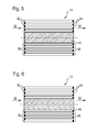
- the interior space 28 is filled with a latent heat store 44, which is shown hatched in FIG. As a result, the interior 28 is closed, and it can no unfiltered exhaust flow unfiltered through the interior and thus to the filter element 14.
- the latent heat accumulator 44 ensures that no impermissibly high operating temperatures occur in the interior of the filter element 14, as by a suitable choice of the material or the material mixture of which the latent heat accumulator 44 is composed, the phase transitions between solid and liquid phase and vice versa in a temperature range can be placed, which is slightly above the usual operating temperature of the Filter element 14 is located and below a temperature at which the filter element 14 would be damaged. This makes it possible to avoid impermissibly high temperatures in the filter element 14 by storing the excess heat energy during the partial or complete phase transformation of the solid into the liquid phase of the latent heat accumulator 44. Once the temperature load of the filter element 14 decreases again, the latent heat stored in the latent heat storage 44 can be released again and the latent heat storage 44 is again partially or completely in the solid phase.
- a filter insert 46 into the interior 28 of the filter element 14. This filter insert 46 can be traversed by the incoming exhaust gas.
- the filter insert 46 consists of a fibrous filter material.
- the center of the filter element 14, where the filter insert 46 is provided directly applied to the exhaust gas from the exhaust pipe 12, so that the dynamic pressure at the inlet surface of the filter insert 46 is higher than at the inlet surface of the filter element 14.
- This effect For example, by a relative to the filter element 14 increased flow resistance of the filter cartridge 46 are taken into account.
- the temperature load of the filter cartridge 46 is naturally higher, since the filter cartridge 46 is surrounded by the filter element 14, which itself has a high operating temperature.
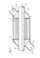
- a filter element 14 according to the invention is integrated in a housing 48.
- a tube 50 is provided through which cooling air or other cooling medium (not shown) can flow.
- the exhaust pipe 12a opens into the left in Figure 7 truncated cone of the housing 48.
- the purified exhaust gas is discharged from the housing 48.
- a tube 50 is passed through the housing 48 and the filter element 14, wherein the tube 50 is gas-tight, so that from the housing 48 no exhaust gas in the Tube 50 can get.
- the tube 50 is traversed by cooling air, it is possible to actively cool the interior of the filter element 14, so as to equalize the temperature conditions in the interior and at the outer edge of the filter element 14 to each other.
- other cooling media such as cooled exhaust gas and other more can be provided in the tube 50 for cooling the filter element 14. It is also possible to open or close the tube 50 in a temperature-controlled manner, so that a temperature control of the filter element 14 is possible.
Landscapes
- Engineering & Computer Science (AREA)
- Chemical & Material Sciences (AREA)
- Combustion & Propulsion (AREA)
- Mechanical Engineering (AREA)
- General Engineering & Computer Science (AREA)
- Physics & Mathematics (AREA)
- Geometry (AREA)
- Chemical Kinetics & Catalysis (AREA)
- Filtering Of Dispersed Particles In Gases (AREA)
- Filtering Materials (AREA)
- Processes For Solid Components From Exhaust (AREA)
Applications Claiming Priority (1)
| Application Number | Priority Date | Filing Date | Title |
|---|---|---|---|
| DE102005049690A DE102005049690A1 (de) | 2005-10-14 | 2005-10-14 | Temperaturvergleichmässigender Innenkanal für ein Filterelement und Filter zur Abgasnachbehandlung |
Publications (2)
| Publication Number | Publication Date |
|---|---|
| EP1775010A2 true EP1775010A2 (fr) | 2007-04-18 |
| EP1775010A3 EP1775010A3 (fr) | 2007-10-17 |
Family
ID=37698189
Family Applications (1)
| Application Number | Title | Priority Date | Filing Date |
|---|---|---|---|
| EP06121825A Withdrawn EP1775010A3 (fr) | 2005-10-14 | 2006-10-05 | Canal interne d'un élément de filtration permettant une homogénéisation de la température et filtre pour traitement des rejets gazeux |
Country Status (2)
| Country | Link |
|---|---|
| EP (1) | EP1775010A3 (fr) |
| DE (1) | DE102005049690A1 (fr) |
Cited By (1)
| Publication number | Priority date | Publication date | Assignee | Title |
|---|---|---|---|---|
| WO2009110970A1 (fr) * | 2008-02-29 | 2009-09-11 | Corning Incorporated | Dispositif de traitement des gaz d’échappement comprenant un composé réactif et conditionnement du dispositif par le biais d'une réaction endothermique |
Families Citing this family (2)
| Publication number | Priority date | Publication date | Assignee | Title |
|---|---|---|---|---|
| DE102006051927A1 (de) * | 2006-11-03 | 2008-05-15 | Robert Bosch Gmbh | Filterelement, insbesondere zur Filterung von Abgasen einer Brennkraftmaschine |
| DE102008040451A1 (de) | 2008-07-16 | 2010-01-21 | Robert Bosch Gmbh | Partikelfilter, Verfahren zum Betrieb und Verfahren zur Herstellung eines solchen Partikelfilters |
Family Cites Families (9)
| Publication number | Priority date | Publication date | Assignee | Title |
|---|---|---|---|---|
| GB1347421A (en) * | 1971-02-10 | 1974-02-27 | Aoi K | Exhaust gas cleaning apparatus for an internal combustion engine |
| GB1395960A (en) * | 1971-09-13 | 1975-05-29 | Ford Motor Co | Catalytic converter |
| JPS6032919A (ja) * | 1983-08-03 | 1985-02-20 | Nippon Soken Inc | モノリス触媒コンバ−タ |
| JPH088243Y2 (ja) * | 1990-08-22 | 1996-03-06 | 日産ディーゼル工業株式会社 | パーティキュレイトフィルタ |
| JP2984436B2 (ja) * | 1991-10-02 | 1999-11-29 | 三菱重工業株式会社 | 触媒マフラ |
| EP0596854A1 (fr) * | 1992-11-02 | 1994-05-11 | AVL Gesellschaft für Verbrennungskraftmaschinen und Messtechnik mbH.Prof.Dr.Dr.h.c. Hans List | Catalyseur |
| EP1312776A3 (fr) * | 2001-11-16 | 2004-05-12 | Isuzu Motors Limited | Système pour la purification de gaz d'échappement |
| JP2004162626A (ja) * | 2002-11-14 | 2004-06-10 | Hitachi Ltd | 排ガス浄化装置 |
| DE102004001421A1 (de) * | 2004-01-09 | 2005-08-04 | Robert Bosch Gmbh | Filtereinrichtung, insbesondere für eine Abgasanlage einer Brennkraftmaschine |
-
2005
- 2005-10-14 DE DE102005049690A patent/DE102005049690A1/de not_active Withdrawn
-
2006
- 2006-10-05 EP EP06121825A patent/EP1775010A3/fr not_active Withdrawn
Cited By (2)
| Publication number | Priority date | Publication date | Assignee | Title |
|---|---|---|---|---|
| WO2009110970A1 (fr) * | 2008-02-29 | 2009-09-11 | Corning Incorporated | Dispositif de traitement des gaz d’échappement comprenant un composé réactif et conditionnement du dispositif par le biais d'une réaction endothermique |
| US8091337B2 (en) | 2008-02-29 | 2012-01-10 | Corning Incorporated | Exhaust treatment device having a reactive compound and conditioning the device via endothermic reaction |
Also Published As
| Publication number | Publication date |
|---|---|
| DE102005049690A1 (de) | 2007-04-19 |
| EP1775010A3 (fr) | 2007-10-17 |
Similar Documents
| Publication | Publication Date | Title |
|---|---|---|
| EP2027373B1 (fr) | Dispositif de filtrage conçu en particulier pour un système de gaz d'échappement d'un moteur à combustion interne | |
| EP0504719B1 (fr) | Filtre pour gaz d'échappement et/ou convertisseur catalytique | |
| EP0593004B1 (fr) | Filtre pour éliminer des polluants de gaz d'échappement | |
| DE102006035052A1 (de) | Filterelement und Filter zur Abgasnachbehandlung | |
| EP1775010A2 (fr) | Canal interne d'un élément de filtration permettant une homogénéisation de la température et filtre pour traitement des rejets gazeux | |
| EP2069615B1 (fr) | Élément filtrant destiné en particulier au filtrage des gaz d'échappement d'un moteur à combustion interne | |
| WO2008052837A1 (fr) | Élément de filtrage notamment destiné à filtrer des gaz d'échappement d'un moteur à combustion interne | |
| DE102007063100A1 (de) | Abgasnachbehandlungseinrichtung mit mindestens zwei Partikelfiltern | |
| WO2009112384A2 (fr) | Dispositif de filtrage notamment destiné à un système de gaz d'échappement d'un moteur à combustion interne | |
| WO2005068050A1 (fr) | Ensemble filtre, en particulier pour un systeme de gaz d'echappement d'un moteur a combustion interne | |
| DE3627734C2 (fr) | ||
| EP2065576A1 (fr) | Système de retraitement des gaz d'échappement et élément de filtre destiné à filtrer les gaz d'échappement d'un moteur diesel | |
| EP1787705A1 (fr) | Dispositif filtrant, en particulier, pour un système de traitement des gaz d'échappement d'un moteur à combustion interne du type Diesel | |
| EP2146062B1 (fr) | Filtre à particules pour moteurs diesel et Otto | |
| DE102005032954B4 (de) | Partikelfilter für Abgase | |
| DE202005011603U1 (de) | Dieselrußpartikelfilter | |
| WO2005059323A1 (fr) | Filtre a particules pour la purification de gaz d'echappement | |
| DE102010008273A1 (de) | Partikelfilteranordnung | |
| DE102005047598A1 (de) | Filterelement und Filter zur Abgasnachbehandlung | |
| DE102015205480A1 (de) | Abgaspartikel-Filtersystem für einen Verbrennungsmotor in der beispielhaften Ausgestaltung als Dieselmotor | |
| DE102006041187B4 (de) | Filterelement, insbesondere zur Filterung von Abgasen einer Brennkraftmaschine | |
| DE202014102219U1 (de) | Abgaspartikel Filtersystem für einen Verbrennungsmotor in der beispielhaften Ausgestaltung als Dieselmotor sowie Fahrzeugantrieb nebst entsprechend ausgestattetem Fahrzeug | |
| DE202006002508U1 (de) | Dieselrußpartikelfilter | |
| DE102014208940A1 (de) | Abgaspartikel-Filtersystem für einen Verbrennungsmotor in der beispielhaften Ausgestaltung als Dieselmotor sowie Fahrzeugantrieb nebst entsprechend ausgestattetem Fahrzeug | |
| EP1944073A1 (fr) | Filtre à particules, en particulier filtre à particules de gaz d'échappement pour un moteur à combustion interne |
Legal Events
| Date | Code | Title | Description |
|---|---|---|---|
| PUAI | Public reference made under article 153(3) epc to a published international application that has entered the european phase |
Free format text: ORIGINAL CODE: 0009012 |
|
| AK | Designated contracting states |
Kind code of ref document: A2 Designated state(s): AT BE BG CH CY CZ DE DK EE ES FI FR GB GR HU IE IS IT LI LT LU LV MC NL PL PT RO SE SI SK TR |
|
| AX | Request for extension of the european patent |
Extension state: AL BA HR MK YU |
|
| PUAL | Search report despatched |
Free format text: ORIGINAL CODE: 0009013 |
|
| AK | Designated contracting states |
Kind code of ref document: A3 Designated state(s): AT BE BG CH CY CZ DE DK EE ES FI FR GB GR HU IE IS IT LI LT LU LV MC NL PL PT RO SE SI SK TR |
|
| AX | Request for extension of the european patent |
Extension state: AL BA HR MK YU |
|
| AKX | Designation fees paid | ||
| STAA | Information on the status of an ep patent application or granted ep patent |
Free format text: STATUS: THE APPLICATION IS DEEMED TO BE WITHDRAWN |
|
| 18D | Application deemed to be withdrawn |
Effective date: 20080418 |
|
| REG | Reference to a national code |
Ref country code: DE Ref legal event code: 8566 |